EP0471107A1 - Méthode et dispositif pour maintenir la symétrie d'un système triphasé - Google Patents
Méthode et dispositif pour maintenir la symétrie d'un système triphasé Download PDFInfo
- Publication number
- EP0471107A1 EP0471107A1 EP90115700A EP90115700A EP0471107A1 EP 0471107 A1 EP0471107 A1 EP 0471107A1 EP 90115700 A EP90115700 A EP 90115700A EP 90115700 A EP90115700 A EP 90115700A EP 0471107 A1 EP0471107 A1 EP 0471107A1
- Authority
- EP
- European Patent Office
- Prior art keywords
- phase
- voltage
- output
- vector
- star
- Prior art date
- Legal status (The legal status is an assumption and is not a legal conclusion. Google has not performed a legal analysis and makes no representation as to the accuracy of the status listed.)
- Ceased
Links
Images


Classifications
-
- H—ELECTRICITY
- H02—GENERATION; CONVERSION OR DISTRIBUTION OF ELECTRIC POWER
- H02M—APPARATUS FOR CONVERSION BETWEEN AC AND AC, BETWEEN AC AND DC, OR BETWEEN DC AND DC, AND FOR USE WITH MAINS OR SIMILAR POWER SUPPLY SYSTEMS; CONVERSION OF DC OR AC INPUT POWER INTO SURGE OUTPUT POWER; CONTROL OR REGULATION THEREOF
- H02M7/00—Conversion of AC power input into DC power output; Conversion of DC power input into AC power output
- H02M7/42—Conversion of DC power input into AC power output without possibility of reversal
- H02M7/44—Conversion of DC power input into AC power output without possibility of reversal by static converters
- H02M7/48—Conversion of DC power input into AC power output without possibility of reversal by static converters using discharge tubes with control electrode or semiconductor devices with control electrode
- H02M7/505—Conversion of DC power input into AC power output without possibility of reversal by static converters using discharge tubes with control electrode or semiconductor devices with control electrode using devices of a thyratron or thyristor type requiring extinguishing means
- H02M7/515—Conversion of DC power input into AC power output without possibility of reversal by static converters using discharge tubes with control electrode or semiconductor devices with control electrode using devices of a thyratron or thyristor type requiring extinguishing means using semiconductor devices only
- H02M7/525—Conversion of DC power input into AC power output without possibility of reversal by static converters using discharge tubes with control electrode or semiconductor devices with control electrode using devices of a thyratron or thyristor type requiring extinguishing means using semiconductor devices only with automatic control of output waveform or frequency
-
- H—ELECTRICITY
- H02—GENERATION; CONVERSION OR DISTRIBUTION OF ELECTRIC POWER
- H02J—ELECTRIC POWER NETWORKS; CIRCUIT ARRANGEMENTS OR SYSTEMS FOR SUPPLYING OR DISTRIBUTING ELECTRIC POWER; SYSTEMS FOR STORING ELECTRIC ENERGY
- H02J3/00—Circuit arrangements for AC mains or AC distribution networks
- H02J3/26—Arrangements for eliminating or reducing asymmetry in polyphase networks
-
- Y—GENERAL TAGGING OF NEW TECHNOLOGICAL DEVELOPMENTS; GENERAL TAGGING OF CROSS-SECTIONAL TECHNOLOGIES SPANNING OVER SEVERAL SECTIONS OF THE IPC; TECHNICAL SUBJECTS COVERED BY FORMER USPC CROSS-REFERENCE ART COLLECTIONS [XRACs] AND DIGESTS
- Y02—TECHNOLOGIES OR APPLICATIONS FOR MITIGATION OR ADAPTATION AGAINST CLIMATE CHANGE
- Y02E—REDUCTION OF GREENHOUSE GAS [GHG] EMISSIONS, RELATED TO ENERGY GENERATION, TRANSMISSION OR DISTRIBUTION
- Y02E40/00—Technologies for an efficient electrical power generation, transmission or distribution
- Y02E40/50—Arrangements for eliminating or reducing asymmetry in polyphase networks
Definitions
- the invention relates to a method and a device for balancing a three-phase system, which is generated by means of an inverter from a DC voltage source, the output of this inverter being provided with a filter with a downstream star point generator.
- a device for producing a symmetrical three-phase output voltage system with resilient neutral conductors is known from European patent specification 0 208 088.
- This device contains an inverter arrangement and a voltage transformation device, in particular a potential-free three-phase voltage transformer with a star-point circuit on the secondary side, which is connected on the primary side to the inverter arrangement.
- a filter is connected in series with the voltage transformation device.
- a setpoint generator specifies three angularly symmetrical setpoints.
- a control device, which is followed by a control rate, is assigned to a setpoint and an AC output of the inverter arrangement.
- a pulse-width-modulated, three-phase bridge converter is provided as the inverter arrangement.
- a decoupling network depicting the structure of the voltage transformation device forms transformed instantaneous values from instantaneous values that correspond to the star voltages at the output of the series circuit, which correspond to a voltage system at the input of the voltage transformation device.
- the control device and the decoupling network are interconnected in such a way that they supply control voltages from the setpoints and from measured values for the star voltages of the output voltage system for the branch pairs working on one output of the inverter arrangement, the control voltages being able to regulate the deviation of the transformed measured values from the setpoints.
- each pair of the inverter arrangement is controlled by its own control set in the manner of an asymmetrical voltage system with a control voltage that is changed quickly.
- the decoupling network makes it possible to convert the measurement variables linked on the secondary side to the loadable star point into replacement measurement variables of a neutral-free system. As a result, replacement actual values of a fictitious voltage system are available for regulation at the input of the voltage transformation device.
- the control voltages formed are asymmetrical.
- the invention is based on the object of specifying a method and a device for the symmetrization of a three-phase system, with the conversion of measured variables linked on the secondary side to the loadable star point into substitute measured variables of a neutral-free system being dispensed with.
- the measured conductor voltages (chained voltage) are each converted into a rotation vector, the amounts of which are then determined. Each actual value value is compared with a predetermined desired value value. The resulting deviations are corrected by a separate control device.
- These formed conductor voltage manipulated variables form the amounts of a voltage system and are each transformed into star voltage manipulated variables, which are then fed to the inverter. With this single-phase magnitude control, a three-phase system can remain symmetrical even with a single-phase load by asymmetrically controlling the amounts of the inverter while maintaining the angular symmetry for the fictitious star system (star voltage manipulated variables).
- the structure of a device according to the invention for carrying out the method for balancing a three-phase system can be found in claim 2.
- the amounts that are supplied as actual values to each control device are determined from the measured line voltages of the three-phase system by means of the amount devices.
- the generated conductor voltage manipulated variables are converted into star voltage manipulated variables with the aid of a transformation device, each of which controls the inverter using a control set.
- the embodiments of the elements of the magnitude device - vector identifier, vector analyzer - are printed from the article "Coordinate transformations for multivariable control systems for the compensation and balancing of three-phase networks", printed in Siemens Forsch.- u. Develop. Ber., Vol. 6 (1977) No. 1, pages 29 to 38.
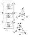
- FIG. 1 shows a device for generating a three-phase system with the outputs R, S and T, consisting of a power section 2 and a control section 4.
- the power section 2 consists of a generator 6, for example a rotating rectifier-excited synchronous generator, which is followed by a rectifier 8 with a downstream DC voltage source 10, for example a voltage intermediate circuit.
- An inverter or reversing converter can also be provided as the rectifier 8.
- An inverter 12 is connected to the voltage intermediate circuit 10 on the input side and is provided with a filter 14 on the output side.
- the filter 14 is followed by a star point former 16, which forms a star point M. This enables a single-phase load.
- a load 20 is connected between the individual three-phase outputs R, S and T of the three-phase system 18 formed and the star point M.
- the generator 6 can be driven, for example, by a thrust engine, with the result that the three-phase system 18 generated is an aircraft electrical system of, for example, 3 ⁇ 115 V, 400 Hz.
- the generator 6 can also be driven by wind power or the voltage intermediate circuit 10 can be a fuel cell, so that the three-phase system 18 represents an island network.
- a supply network can also be provided, so that the three-phase system 18 generated (uninterruptible power supply) is a secure three-phase system.
- the regulating part 4 contains on the input side three converters 22, 24 and 26 with which the three output voltages of the filter 14 are detected as the line voltage URL , u SL and u TL .
- These measured conductor voltages URL , u SL and u TL are each supplied to a magnitude device 28, 30 and 32, at whose outputs the amount u R , ü s and û T of the conductor voltages u RL , u SL and u TL are present.
- the amount ü R or ü s or û T is fed as an actual value to a minus input of a comparator 34 or 36 or 38.
- a setpoint û * R or û * s or û * T is available at the plus input of this comparator 34 or 36 or 38.
- the control difference value ü Re or ü se or ü Te generated depending on the actual value ü R or ü s or û T and the target value û * R or û * S or û * T becomes an amount controller 42 or 44 or 46, which is followed by an adder 48 or 50 or 52.
- the value U RR or U RS or U RT generated by the controller 42 or 44 or 46 is fed to one input of the adder 48 or 50 or 52, at the second input of which the setpoint value û * R or û * S or û * T is pending.
- a so-called pilot control - is obtained a manipulated variable U stR or U sts or U StT .
- the pre-control makes the control faster, since only small target-actual differences need to be corrected.
- a PI regulator can be used as the quantity regulator 42 or 44 or 46, which regulates the target / actual difference to zero.
- the line voltage manipulated variables U RtR , U sts and U StT must be transformed into star voltage manipulated variables U S tr, Usts and U stt .
- This is done with a transformation device 54 which is connected on the input side to the outputs of adders 48, 50 and 52 and on the output side by means of a control rate 96, 98 and 100 to a pair of branches of the inverter 12.
- the three tax rates 96,98,100 are controlled angularly symmetrical (120 °).
- the star voltage manipulated variable U Str or U sts or U stt is made up of the three conductor voltage manipulated variables U stR , Usts and Ust T according to the equation respectively. respectively. generated.
- These transformed star voltage manipulated variables U Str , U sts and U stt cause at the input of Filters 14 an angularly symmetrical voltage system R ', S' and T 'with unequal amounts, which results in a symmetrical voltage system R, S and T at the output of the filter 14 with an unbalanced load (single-phase load).
- a vector diagram of these voltage systems R ', S' and T 'and R, S and T are shown in more detail in FIG. 5 (no balancing) and in FIG. 6 (balancing).
- the magnitude device 28 or 30 or 32 of the control part 4 has on the input side a vector identifier 56 or 58 or 60 with a downstream vector analyzer 62 or 64 or 66 and on the output side an actual value smoothing 68 or 70 or 72.
- the vector identifier 56 or 58 or 60 has the task of, for example, represented by a given vibration a rotation vector to determine. In other words, the task of the vector identifier 56 or 58 or 60 is to determine the associated sine vibration for the given cosine vibration.
- An embodiment is shown in more detail in Figure 2. This determined rotation vector u R or u s or u T is fed to the vector analyzer 62 or 64 or 66.
- An exemplary embodiment of the vector analyzer 62 or 64 or 66 is shown in more detail in FIG. 3.
- This vector analyzer 62 or 64 or 66 determines the magnitude of the rotation vector u R or u s or u T according to the following equation: This determined amount û ' R or û ' S or û ' T is smoothed by means of actual value smoothing 68 or 70 or 72, since the voltages URL or u SL or UTL at the output of filter 14 are subject to harmonics. At the output of the magnitude device 28 or 30 or 32, an amount ü R or ü s or ü T is available, which is supplied to comparator 34 or 36 or 38 as an actual value.
- the vector identifiers 56, 58 and 60 is shown in more detail in FIG.
- this vector identifier 56 which is intended to determine an associated sine oscillation for a given cosine oscillation, can consist of a delay element.
- the vector identifier 56 consists of a delay element 74, two factors 76 and 78 and an adder 80. The input of the vector identifier 56 is on the one hand directly with the output of the vector identifier 56 and on the other hand with the delay element 74 and on the other hand associated with the factor 76.
- the outputs of the delay element 74 and the factor 76 are linked to one another by means of the adder 80, the output of the adder 80 being linked to the output of the vector identifier 56 via a factor 78.
- a rotation vector u R is present at the output.
- FIG. 3 shows the vector analyzer 62 in a representative manner for the three vector analyzers 62, 64 and 66.
- the vector analyzer 62 consists of two squarers or multipliers 82 and 84, an adder 86 and an eraser 88.
- the eraser 88 can be omitted if the target values are constant.
- the real part Re u R and the imaginary part Im u R of the rotation vector u R are fed to the inputs x and y of the multipliers 82 and 84, respectively.
- the square of the real part Re u R and the imaginary part Im u R are at their outputs.
- the transformation device 54 according to FIG. 1 is shown in more detail in FIG.
- the star voltage manipulated variable U st or U sts or U stt is made up of the phase voltage manipulated variables U stR , U sts and U stT according to the following equations respectively. respectively. certainly.
- the factor is equal to the factor 0.577.
- the transformation device 54 thus consists of three adders 90, 92 and 94, at the inputs of which the weighted line voltage manipulated variables U stR , U sts and U stT are present.
- the star voltage manipulated variable U S tr or Usts or Ustt is then present at the output of the adder 90 or 92 or 94.
- FIG. 5 shows the voltage system R ', S' and T ', which is present at the input of the filter 14, and the voltage system R, S and T, which occurs at an unbalanced load or asymmetrical load at the output of the filter 14.
- the inverter 12 has a symmetrical control for the amounts in the case of an angle-symmetrical specification. Due to the different voltage drops AR, AS and AT - asymmetrical load - the asymmetrical voltage system R, S and T is set at the output of the filter 14.
- This voltage system R, S and T can be symmetrized if the amounts in the angularly symmetrical system R ', S' and T 'are set individually and differently from one another such that a symmetrical voltage system R, S and T is established at the output of the filter 14. that is, the amounts of the symmetrical voltage system R, S and T are equal to the setpoint values û * R , û * S and û * T. It can be seen in the vector diagram in FIG. 6 that the individual amounts of the angularly symmetrical voltage system R ', S' and T 'are very different from one another and that the voltage system R, S and T which arises at the output of the filter 14 is symmetrical, although an unbalanced load is present is.
Landscapes
- Engineering & Computer Science (AREA)
- Power Engineering (AREA)
- Supply And Distribution Of Alternating Current (AREA)
- Inverter Devices (AREA)
Priority Applications (3)
| Application Number | Priority Date | Filing Date | Title |
|---|---|---|---|
| EP90115700A EP0471107A1 (fr) | 1990-08-16 | 1990-08-16 | Méthode et dispositif pour maintenir la symétrie d'un système triphasé |
| US07/742,026 US5148361A (en) | 1990-08-16 | 1991-08-08 | Method and device for balancing the circuits of a three-phase system |
| JP3229476A JPH04248369A (ja) | 1990-08-16 | 1991-08-14 | 三相系の対称化方法および装置 |
Applications Claiming Priority (1)
| Application Number | Priority Date | Filing Date | Title |
|---|---|---|---|
| EP90115700A EP0471107A1 (fr) | 1990-08-16 | 1990-08-16 | Méthode et dispositif pour maintenir la symétrie d'un système triphasé |
Publications (1)
| Publication Number | Publication Date |
|---|---|
| EP0471107A1 true EP0471107A1 (fr) | 1992-02-19 |
Family
ID=8204340
Family Applications (1)
| Application Number | Title | Priority Date | Filing Date |
|---|---|---|---|
| EP90115700A Ceased EP0471107A1 (fr) | 1990-08-16 | 1990-08-16 | Méthode et dispositif pour maintenir la symétrie d'un système triphasé |
Country Status (3)
| Country | Link |
|---|---|
| US (1) | US5148361A (fr) |
| EP (1) | EP0471107A1 (fr) |
| JP (1) | JPH04248369A (fr) |
Cited By (1)
| Publication number | Priority date | Publication date | Assignee | Title |
|---|---|---|---|---|
| WO2010076079A1 (fr) * | 2008-12-29 | 2010-07-08 | Siemens Aktiengesellschaft | Convertisseur multi-niveaux en tant que compensateur de puissance réactive avec symétrisation de puissance active |
Families Citing this family (8)
| Publication number | Priority date | Publication date | Assignee | Title |
|---|---|---|---|---|
| JP3411462B2 (ja) * | 1997-02-05 | 2003-06-03 | 三菱電機株式会社 | 電力変換器の制御装置 |
| WO2000022487A1 (fr) * | 1998-10-08 | 2000-04-20 | Siemens Aktiengesellschaft | Dispositif de regulation pour la regulation d'un systeme asservi a plusieurs grandeurs reglees couplees |
| US6239997B1 (en) * | 2000-09-01 | 2001-05-29 | Ford Motor Company | System for connecting and synchronizing a supplemental power source to a power grid |
| US6919650B2 (en) * | 2002-05-31 | 2005-07-19 | Ballard Power Systems Corporation | Hybrid synchronization phase angle generation method |
| FI114353B (fi) * | 2003-03-14 | 2004-09-30 | Abb Oy | Jännite-epäsymmetrian kompensointimenetelmä |
| US20090295231A1 (en) * | 2008-05-30 | 2009-12-03 | Gaffney Shawn J | Intelligent Power Collection Network |
| US20120218789A1 (en) * | 2011-02-25 | 2012-08-30 | Phillip Gerard Langhorst | Electrical Power Conditioner |
| US9997995B2 (en) | 2013-02-28 | 2018-06-12 | Hewlett-Packard Enterprise Development LP | Three-phase parallel power converter load adjustment |
Citations (2)
| Publication number | Priority date | Publication date | Assignee | Title |
|---|---|---|---|---|
| DE3236071A1 (de) * | 1982-07-09 | 1984-01-12 | Siemens AG, 1000 Berlin und 8000 München | Vorrichtung zur paralleleinspeisung in ein wechsel- oder drehstromnetz |
| EP0208088A1 (fr) * | 1985-05-13 | 1987-01-14 | Siemens Aktiengesellschaft | Dispositif pur l'obtention d'un système de tensions triphasées avec conducteur neutre chargeable |
Family Cites Families (6)
| Publication number | Priority date | Publication date | Assignee | Title |
|---|---|---|---|---|
| JPH01152928A (ja) * | 1987-12-09 | 1989-06-15 | Toshiba Corp | 電力変換装置の制御装置 |
| US4922400A (en) * | 1989-08-03 | 1990-05-01 | Sundstrand Corporation | Neutral forming circuit |
| US5008801A (en) * | 1989-12-11 | 1991-04-16 | Sundstrand Corporation | VSCF power conversion system using an output autotransformer |
| US5055992A (en) * | 1990-01-29 | 1991-10-08 | Sundstrand Corporation | Control for full-bridge inverter |
| US4994956A (en) * | 1990-04-25 | 1991-02-19 | Sundstrand Corporation | Enhanced real time control of PWM inverters |
| US4977492A (en) * | 1990-04-25 | 1990-12-11 | Sundstrand Corporation | Suppression of switching harmonics |
-
1990
- 1990-08-16 EP EP90115700A patent/EP0471107A1/fr not_active Ceased
-
1991
- 1991-08-08 US US07/742,026 patent/US5148361A/en not_active Expired - Fee Related
- 1991-08-14 JP JP3229476A patent/JPH04248369A/ja not_active Withdrawn
Patent Citations (2)
| Publication number | Priority date | Publication date | Assignee | Title |
|---|---|---|---|---|
| DE3236071A1 (de) * | 1982-07-09 | 1984-01-12 | Siemens AG, 1000 Berlin und 8000 München | Vorrichtung zur paralleleinspeisung in ein wechsel- oder drehstromnetz |
| EP0208088A1 (fr) * | 1985-05-13 | 1987-01-14 | Siemens Aktiengesellschaft | Dispositif pur l'obtention d'un système de tensions triphasées avec conducteur neutre chargeable |
Non-Patent Citations (1)
| Title |
|---|
| SIEMENS FORSCH. U. ENTWICKL.-BER., Band 6, Nr. 1, 1977, Seiten 29-38, Springer-Verlag, Berlin, DE; W. MEUSEL et al.: "Coordinate transformations of multi-term regulation systems for the compensation and symmetrization of three-phase supplies" * |
Cited By (3)
| Publication number | Priority date | Publication date | Assignee | Title |
|---|---|---|---|---|
| WO2010076079A1 (fr) * | 2008-12-29 | 2010-07-08 | Siemens Aktiengesellschaft | Convertisseur multi-niveaux en tant que compensateur de puissance réactive avec symétrisation de puissance active |
| US8653799B2 (en) | 2008-12-29 | 2014-02-18 | Siemens Aktiengesellschaft | Multilevel converter as reactive power compensator having active |
| RU2519815C2 (ru) * | 2008-12-29 | 2014-06-20 | Сименс Акциенгезелльшафт | Многоуровневый преобразователь в качестве компенсатора реактивной мощности с симметрированием активной мощности |
Also Published As
| Publication number | Publication date |
|---|---|
| JPH04248369A (ja) | 1992-09-03 |
| US5148361A (en) | 1992-09-15 |
Similar Documents
| Publication | Publication Date | Title |
|---|---|---|
| EP0471106A1 (fr) | Méthode et dispositif pour maintenir la symétrie d'un système triphasé | |
| EP0037001B1 (fr) | Dispositif pour onduleur | |
| EP2059999B1 (fr) | Procede de regulation pour onduleurs | |
| DE69920424T2 (de) | Verfahren zur Steuerung eines Wirkleistungsflusses in einem Hochspannungsgleichstrom-Übertragungssystem | |
| DE3785258T2 (de) | Induktionsmaschinensystem. | |
| DE69936505T2 (de) | Regelvorrichtung für einen induktionsmotor | |
| DE19642596A1 (de) | Verfahren und Vorrichtung zur Kompensation von Blindstromanteilen mittels einer Kompensationseinrichtung mit einem Pulsstromrichter | |
| EP2027648A1 (fr) | Limiteur de courant pour une machine asynchrone à double alimentation | |
| EP0208088B1 (fr) | Dispositif pur l'obtention d'un système de tensions triphasées avec conducteur neutre chargeable | |
| EP0471107A1 (fr) | Méthode et dispositif pour maintenir la symétrie d'un système triphasé | |
| DE69409987T2 (de) | Vorrichtung zum Unterdrücken von Spannungsschwankungen und Oberschwingungen | |
| DE3429116C2 (fr) | ||
| EP0701743B1 (fr) | Procede et dispositif permettant de reduire les tensions asymetriques dans un reseau triphase au moyen d'un compensateur statique | |
| DE2502513A1 (de) | Schaltungsanordnung mit einer anzahl von umrichtern, insbesondere von direktumrichtern in sternschaltung | |
| DE112021002269T5 (de) | Leistungsumwandlungsvorrichtung | |
| DE3029311C2 (fr) | ||
| DE3243701C2 (de) | Verfahren und Schaltungsanordnung zur dynamischen Blindleistungskompensation und Symmetrierung von unsymmetrischen Netzen und Lasten mit Stromrichtern | |
| EP3311481B1 (fr) | Procédé de commande d'un convertisseur de source de tension, convertisseur de source de tension, et installation de transfert d'énergie électrique | |
| DE10032447A1 (de) | Verfahren zur Stromoberschwingungskompensation bei gepulsten Netzstromrichtern mit Spannungszwischenkreis | |
| DE3738180C2 (de) | Verfahren und Vorrichtung zur Regelung der Ausgangsgleichspannung eines selbstgeführten Netzstromrichters | |
| EP4147336A1 (fr) | Procédé de régulation et conversion de grilles pour fonctionnement dans des grilles à phase unique déformées | |
| EP0796517A1 (fr) | Procede et dispositif de generation d'un systeme de distribution d'ordre n a m-phases dans un dispositif alimente par un convertisseur | |
| DE10244056B3 (de) | Verfahren zum Erzeugen eines Satzes von Steuersignalen für einen Umrichter eines aktiven Filters zur Kompensation von Oberschwingungen und anderen Schwingungen und Vorrichtung zur Durchführung derselben | |
| EP2384528B1 (fr) | Procédé pour équilibrer les tensions de circuit intermédiaire dans un compensateur à courant réactif multiniveau autopiloté et compensateur à courant réactif multiniveau autopiloté | |
| DE1905296A1 (de) | Gleichstromkraftuebertragung mit stabilisierender Wirkung |
Legal Events
| Date | Code | Title | Description |
|---|---|---|---|
| PUAI | Public reference made under article 153(3) epc to a published international application that has entered the european phase |
Free format text: ORIGINAL CODE: 0009012 |
|
| 17P | Request for examination filed |
Effective date: 19901205 |
|
| AK | Designated contracting states |
Kind code of ref document: A1 Designated state(s): AT BE CH DE DK ES FR GB GR IT LI LU NL SE |
|
| RBV | Designated contracting states (corrected) |
Designated state(s): DE FR GB IT SE |
|
| 17Q | First examination report despatched |
Effective date: 19930809 |
|
| STAA | Information on the status of an ep patent application or granted ep patent |
Free format text: STATUS: THE APPLICATION HAS BEEN REFUSED |
|
| 18R | Application refused |
Effective date: 19940131 |