EP0471307A2 - Système évolué de mesure d'horloges - Google Patents
Système évolué de mesure d'horloges Download PDFInfo
- Publication number
- EP0471307A2 EP0471307A2 EP91113413A EP91113413A EP0471307A2 EP 0471307 A2 EP0471307 A2 EP 0471307A2 EP 91113413 A EP91113413 A EP 91113413A EP 91113413 A EP91113413 A EP 91113413A EP 0471307 A2 EP0471307 A2 EP 0471307A2
- Authority
- EP
- European Patent Office
- Prior art keywords
- output
- zero
- signal
- counting
- clocks
- Prior art date
- Legal status (The legal status is an assumption and is not a legal conclusion. Google has not performed a legal analysis and makes no representation as to the accuracy of the status listed.)
- Withdrawn
Links
Images


Classifications
-
- G—PHYSICS
- G04—HOROLOGY
- G04D—APPARATUS OR TOOLS SPECIALLY DESIGNED FOR MAKING OR MAINTAINING CLOCKS OR WATCHES
- G04D7/00—Measuring, counting, calibrating, testing or regulating apparatus
- G04D7/12—Timing devices for clocks or watches for comparing the rate of the oscillating member with a standard
- G04D7/1207—Timing devices for clocks or watches for comparing the rate of the oscillating member with a standard only for measuring
Definitions
- the present invention relates to a method and system for measuring the time difference between a plurality of high-precision clocks. More particularly, the present invention relates to a simplified extended dual mixer time difference measurement system which employs a common oscillator as opposed to a synthesizer, thereby reducing the cost of the system and eliminating noise produced by a synthesizer.
- Molecular clocks employ a molecular material, such as cesium or rubidium, which has a frequency output of a value which is essentially determined by the inherent characteristics of the material.
- NBS National Bureau of Standards
- the NBS time standard has been made available globally via satellites.
- the "time” has become available to parties at remote locations having the appropriate hardware and means for processing the signals.
- These signals alone or in combination, were and remain used for several applications. For example, navigation systems of ships at sea utilize time signals from three or more of such satellites to determine their location.
- these applications require specialized receiving equipment, and are subject to problems from a number of sources, such as atmospheric interference, etc. Therefor, applications which require extremely high precision, reliability and/or some sort of detection avoidance are not best served by the satellite time signals.
- the extended dual mixer time difference measurement technique ties the "time" from each clock to a time base, which is a signal having a known frequency synthesized from one of the clocks in the ensemble.
- One significant feature of the extended dual mixer technique is the use of scalers to count zero upcrossings in the beat signal derived from each clock.
- the extended dual mixer technique eliminated the ambiguity problem by adding scalers to count the zero upcrossing of each cycle of the beat signal for each clock. In this way, both the phase difference and the cycle ambiguity between clocks in an ensemble could be ascertained.
- This time measurement system required less supervision than its predecessors and provided data to a computer which permitted a more accurate representation of the time to be derived from the ensemble.
- one object of the present invention is to provide a simplified and reliable extended dual mixer time difference measurement system.
- a further object of the present invention is to provide a clock measurement system which is less expensive to manufacture.
- Another object of the present invention is to provide an advanced clock measurement system which operates without a synthesizer.
- Yet another object of the present invention is to provide an advanced clock measurement system which has less inherent noise.
- Yet another object of the present invention is to provide an inexpensive advanced clock measurement system which can be utilized in a variety of applications.
- a still further object of the present invention is to provide a clock measurement system which can obtain a more accurate analysis of ensemble time.
- a measurement system for observing time differences between at least two oscillators of an ensemble comprises: a common oscillator, separate from the oscillators of the ensemble for producing a first output signal; a mixer associated with each of the oscillators of the ensemble for mixing an output signal from its associated oscillator with the first output signal; a divider for dividing the output signal from a first of the oscillators of the ensemble; a counter for counting zero crossings of each of the signals output by the mixers and the divider; counters for counting the time intervals between the zero crossings of the mixer associated with the first oscillator and the mixers associated with the remaining oscillators and the dividers; and a computer for determining time differences between the at least two oscillators based on the counted zero crossings and the counted time intervals.
- the zero crossings are zero upcrossings of the respective signals
- the divider comprises a synchronous divider.
- the divider can also synchronize the divided signal with an externally supplied signal.
- the oscillators measured by the system can be molecular or, more particularly, cesium clocks.
- the present invention also discloses a system for measuring the phase differences between clocks in an ensemble, comprising: an common oscillator for producing a first signal; a divider for dividing a signal output by a first clock of the ensemble; a scaler for counting the zero upcrossings of the divided signal; a plurality of channels, one associated with each clock in the ensemble and each comprising a mixer for mixing an output signal of its associated clock with the first signal, a detector for detecting zero upcrossings of the output of the mixer, a counter for counting a time interval between a start signal and the zero upcrossing of the associated clock, and a counter for counting the number of zero upcrossings detected by the detector; and a computer or like device for determining the phase differences between the clocks of the ensemble based on the output of the scaler and the counters of each channel.
- the start signal is a zero upcrossing of the divided signal for the channel associated with the first clock and a zero upcrossing of the mixed signal from the first channel for the remaining clocks.
- the divider is preferably a synchronous divider and can synchronize the signal from the first clock with an external signal.
- the present invention further discloses a measurement system for observing time differences between at least two measuring oscillators comprising: a common oscillator, separate from the measuring oscillators, for producing a first output signal; at least two mixers, one associated with each of the measuring oscillators, each for mixing an output signal from the associated oscillator with the first output signal; a divider for dividing the output signal from a first of the measuring oscillators; detectors and counters for detecting and counting respective zero crossings of respective signals output from each of the mixers and the divider; time interval counters for counting time intervals between the zero crossings of the output of the divider and the outputs of each of the mixers; and a computer or processor for determining time differences between the measuring oscillators based on the counted zero crossings and counted time intervals.
- the detectors and counters detect and count zero upcrossings of the respective signals and comprise zero crossing detectors, one associated with each of the mixers, for detecting the zero upcrossings, and scalers, one operatively connected with each of the divider and the zero crossing detectors, for counting the zero upcrossings.
- the time interval counters preferably comprises a time interval counter operatively associated with each of the zero crossing detectors.
- Each of the time interval counters has a start input and a stop input, the start input of each time interval counter being connected to the output of the divider and the stop input of each time interval counter being connected to the output of its associated zero crossing detector.
- FIG. 1 An extended dual mixer time difference measurement system 10 is illustrated in Fig. 1.
- Two clocks or oscillators 12, 14 are illustrated in Fig. 1, but the system 10 can be expanded to accommodate any number of oscillators by adding an appropriate channel for each additional oscillator.
- each oscillator is a molecular clock of the same type, so that each produces an output frequency value which is approximately known and substantially similar.
- a frequency synthesizer 16 produces a signal with a known frequency offset from the output signal of the first oscillator 12, which is mixed with the output signals of the oscillators 12, 14 in mixers 18, 20, respectively.
- the output frequency of the synthesizer, v s is equal to ⁇ 1 (1-1/R) where 1'1 is the frequency of the first oscillator 12 and R is any rational number.
- the output signal from the first mixer 18, also known as a beat signal, has a frequency equal to the frequency difference between the frequencies of the signals output by the first oscillator 12 and the synthesizer 16.
- the output signal from the second mixer 20 has a frequency equal to the frequency difference between the signals output from the second oscillator 14 and the synthesizer 16. Since the frequencies of the signals output from the respective oscillators 12, 14 should be very close and the frequency of the signals applied to each mixer 18, 20 from the frequency synthesizer 16 is the same, the difference in frequency of the signals output from the first and second mixers 18, 20 should be small.
- the frequency of the synthesized signal is relatively close to the frequency of the oscillators 12, 14, such that the frequencies of the beat signals output from the mixers 18, 20 are very low, such as on the order of 1 Hz to 1000 Hz.
- phase difference is found by detecting when each respective signal has a positive zero crossing, which is also referred to as a zero upcrossing. Respective zero upcrossings are detected by respective zero crossing detectors 22, 24.
- a time interval counter 26 is programmed to start counting when the first zero crossing detector 22 detects that the beat signal output from the first mixer 18 has a zero upcrossing, and to stop counting when the second zero crossing detector 24 detects that the beat signal output from the second mixer 20 has a zero upcrossing.
- the quantity P counted by the time interval counter 26 represents the phase difference between the first and second oscillators 12, 14 modulo 2 1T .
- a second time interval counter 32 is provided in the channel associated with the first oscillator 12, but provides no additional information. To allow any channel to be used for the reference, each channel is assembled including a time interval counter. Since one channel is provided for each clock being measured, the time interval counter in one channel in the system (the reference channel) will always remain unused.
- the extended dual mixer system also accounts for phase differences on a different scale. Relatively large differences in frequency which may result in the beat signals having completed a different number of cycles over a given time period. This second magnitude of phase difference (also referred to as a difference in the epoch) is relatively common over longer periods of time.
- Scalers 28 and 30 count zero upcrossings M and N of the respective beat signals over a given period of time.
- a computer (not shown) then processes data output from the time interval counter 26 and the scalers 28, 30 first to determine the average frequency of the oscillators 12, 14 and then to determine the time difference between the outputs.
- the counter outputs are combined to calculate the total phase difference between the oscillators as follows: where q)(t) represents phase, Tc is the period of the time interval counter time base, PB2 (t M ;t N ) is the average beat frequency and P is the number of counts recorded in a measurement.
- the first term is a constant which represents the choice of the time origin and can be ignored. The last two terms and their sum are plotted in Fig. 2.
- the average beat frequency PB2 (t M ;t N ) cannot be known exactly. However, it may be estimated with sufficient precision from the previous pair of measurements, designated ' (prime) and " (double prime), respectively.
- the average frequency is approximately
- the extended dual mixer system provides high resolution, is fully automatic due to the elimination of the ambiguity, outputs no phase errors caused by the switching of RF signals since there is no switching anywhere in the system, and is capable of comparing a very large number of oscillators.
- some problems still exist. For example, even though the system provides high resolution, the resolution is limited by noise to approximately 2 ps. Much of this noise is caused by the frequency synthesizer. Besides being the cause of excessive noise, the frequency synthesizer is one of the more expensive and complicated components in the system. For a variety of reasons, frequency synthesizers are commonly the source of output errors. Frequency synthesizers are prone to phase variations due to environmental factors, such as temperature and humidity.
- the present inventor has responded to these problems in a unique manner.
- a synthesizer was required in order to provide a signal having a known frequency offset from the reference oscillator in order to be able to compare the output signals from a plurality of oscillators.
- the present inventor found that it is not necessary to use a synthesizer to calibrate a frequency offset from a common oscillator with respect to a reference clock. Rather, a simple circuit is used to provide the necessary information. The result is an improved extended dual mixer system which requires no synthesizer.
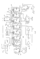
- This advanced clock measurement system 50 is illustrated in Fig. 3.
- Fig. 3 is a circuit diagram of an advanced clock measurement system according to the present invention.
- An advanced clock measurement system 50 performs the same function as the prior art extended dual mixer system, but differs from the prior art extended dual mixer system in that the frequency synthesizer has been eliminated. Instead, an additional clock is required, which acts as a common oscillator, and a divider and an additional scaler have been added to the measurement circuit itself. The operation of the advanced clock measurement system 50 of Fig. 3 will now be described.
- the advanced clock measurement system of the present invention is capable of being expanded to accommodate an ensemble having any number of clocks or oscillators.
- the advanced clock measurement system illustrated in Fig. 3 includes two oscillators 52, 54 which comprise an ensemble.
- the oscillators 52, 54 are the same type of molecular clocks, such as cesium clocks.
- a channel is associated with each oscillator of the ensemble and includes a mixer, a zero crossing detector, a time interval counter and a scaler for processing the signal from the associated oscillator, as will be described below.
- a common oscillator 56 which is preferably a tunable oscillator with good short term frequency stability, outputs a signal to respective first inputs of a first mixer 58 and a second mixer 60.
- An output signal from the first oscillator 52 is provided to a second input of the first mixer 58.
- the resulting beat signal output from the first mixer 58 has a frequency equal to the frequency difference between the first and second inputs to the first mixer 58.
- the signal output from the second oscillator 54 is input to a second input of the second mixer 60, and the beat signal output from the second mixer 60 has a frequency equal to the frequency difference between the outputs of the second oscillator 54 and the common oscillator 56.
- the mixer output is the frequency difference between oscillators, but the phase error is preserved so that it corresponds to an absolutely longer time interval. For example, 1T radians at 5 MHz is 100 ns, but 1T radians at 10 Hz is 0.05 s.
- the synthesizer Since the advanced clock measurement system has eliminated the synthesizer, another way must be found to compare the outputs of clocks in an ensemble without the use of time base tied to one of the clocks (the synthesized signal of the extended dual mixer system). Additionally, the frequency of the first oscillator 52 relative to second oscillator 54 must be mathematically described without the use of the frequency of the common oscillator. This is possible through the use of a divider 62 and a scaler 64. In this way, the output of the first mixer 58 is tied to the output of the divider 62, and the frequency of the first oscillator 52 relative to the second oscillator 54 can be determined, as is explained below.
- the first oscillator 52 is a cesium clock.
- An ideal cesium clock has a frequency of 9,192,631,770 Hz, and time is measured using cesium clocks based on this ideal frequency. (As discussed above, the present invention resolves inaccuracy which arises from frequency offsets from this ideal frequency.)
- the divider 62 is used to change the frequency output by the first oscillator 52 into one more nearly equal to the frequency difference between oscillators 52 and 56 by dividing the frequency by a constant Q.
- the signal can also be synchronized to an externally applied signal, or the signal can be further divided by a second divider 78 to obtain a signal having a different frequency, such as on the order of 1 pulse per second (pps), as will be explained below with reference to Fig. 4.
- the scaler 64 then counts the zero upcrossings of the signal output by the divider 62.
- the signal output from the divider 62 is also used as a start signal for a first time interval counter 66.
- a first zero crossing detector 68 detects the zero upcrossing of the beat signal output from the first mixer 58. Upon detection of a zero upcrossing, the first zero crossing detector 68 outputs a signal which acts as a stop signal for the first time interval counter 66.
- the signal output by the first zero crossing detector 68 is counted by a second scaler 70 and acts as a start signal for a second time interval counter 72 in the channel associated with the second oscillator 54.
- a second zero crossing detector 74 detects zero upcrossings in the beat signal output by the second mixer 60. Upon detection of a zero upcrossing, the second zero crossing detector 74 outputs a signal which acts as a stop signal for the second time interval counter 72 and is counted by a third scaler 76. If the ensemble included more oscillators, additional channels would be required, one associated with each additional oscillator. The channels would be connected in parallel as described above, relative to the channels for the first and second oscillators 52, 54.
- the outputs from the first, second and third scalers 64, 70, 76 and the first and second time interval counters 66, 72 are provided to a computer for calculating the phase difference between the first and second oscillators 52, 54.
- the output of the first scaler 64 which is the number of zero upcrossings during a given measurement period of the divided signal, is represented by K.
- the output of the first time interval counter 66 is represented by P 1 .
- the output of the second scaler 70 which is the number of zero upcrossings of the beat signal derived from the first oscillator 52, is represented by N 1 .
- the output of the second time interval counter 72 is represented by P 2 .
- the output of the third scaler 76 which is the number of zero upcrossings of the beat signal derived from the second oscillator 54, is represented by N 2 .
- a computer or processor of some type is employed to calculate the phase difference between the first and second oscillators by using the following relationships and calculations.
- the total phase of an oscillator is represented by 4)(t). If the start time of the first interval counter 66 is designated to, then the phase of the first oscillator 52 can be represented by
- the second time interval counter 72 starts on the stop pulse of the first time interval counter 66, which is ti. Given that the stop time for the second time interval counter 72 is t 2 , the phase difference between the second oscillator 54 and the common oscillator 56 at time t 2 is
- the phase difference between the first and second oscillators 52, 54 can be obtained by subtracting equation (4) from equation (5) as follows: where ⁇ 1c (t 2 - t 1 ), defined as is the average frequency of the first oscillator 52 relative to the common oscillator 56 over the time interval from ti to t 2 , and N 1 (t 1 ) and N 2 (t 2 ) are the number of zero crossings counted by scalers 70, 76 at times t 1 and t 2 , respectively.
- the start and stop of the first time interval counter 66 are related by where P 1 (t 1 ) is the number of counts accumulated during the measurement cycle. Evaluating this relationship at the earlier time, subtracting and substituting equation (3), the expression for the elapsed time between stop pulses for the two measurements is as follows:
- the time difference t 2 - t 1 is just .
- the four average frequencies of the first oscillator 52 are not known, but negligible errors are made if they are all set to equal ⁇ 1 (to/to), the optimum estimate of the frequency of the first oscillator 52 at time to based on all measurements through time to. The final result is
- the phase difference between the oscillators can thus be calculated. If the first oscillator operates at nominal 5 MHz frequency stable to 10- 12 over one second, then the approximation results in a fractional error of order 10- 12 cycle or 2 X 10 -19 second.
- Fig. 4 illustrates a circuit diagram of an alternative circuit for the advanced clock measurement system according to the present invention.
- measured time intervals each have the same start time.
- the time of each phase difference measurement is referenced to the same time.
- the output signal from the divider 62 is employed as the start signal for each time interval counter in the circuit, as illustrated in Fig. 4.
- phase difference As in the original circuit (Fig. 3), a computer or processor of some type is employed to calculate the phase difference between the first and second oscillators. However, given that the start time is now the same for each time interval counter, the phase difference (as provided by Equation 12 in the first embodiment) will be slightly different from that for the first embodiment. All other factors and variables being the same, it can be shown that the phase difference for this circuit will be
- the phase difference between the oscillators can be calculated using the time intervals and zero upcrossings measured by this circuit.
- Fig. 5 is a more detailed circuit diagram of the dividers 62, 78.
- a signal from oscillator can be synchronized to within 100 ns with an external digital signal having a frequency of one pulse per second and such that the signal output by the divider 62 may also be offset by a desired amount, such as 100 msec.
- the divider 62 can be used in combination with the second divider 78 to produce a 1 pps output signal. The operation of the divider will now be discussed.
- the divider 62 illustrated in Fig. 5 employs a number of TTL components, although the same function can be performed with other types of components.
- the analog input signal from the first oscillator 52 is converted into a TTL signal by a comparator 80.
- the TTL signal is then input to a synchronous divider with ripple carry 82.
- the synchronous divider 82 includes a series of decade stages 84-96 which are connected in series.
- the counters 84-96 are clocked together such that there is only a one-gate delay from the input to the final output.
- the square wave signal from the oscillator 52 via the comparator 80 is used as the clock input CK for each of the stages 84-96.
- a one pulse per second synchronizing signal is input to a clock input of an optional flip-flop 98.
- the Q output of the flip-flop 98 is used as the clear input CLR for each of the counters 84-96.
- an optional circuit which includes a momentary push-button switch 100, an invertor 102, a flip-flop 104, a NAND gate 106 and a seven decade BCD switch 108 provide the desired offset.
- the RCO output from the last series- connected decade stage 96 is inverted by the invertor 102 and provided as the clock input CLK of the flip-flop 104.
- the Q output of the flip-flop 104 and the RCO output of the last divider 96 drive the NAND gate 106, the output of which is used as the LD input to load data into each of the decade stages 84-96.
- the BCD switch 108 provides the data for data inputs A, B, C, and D of each decade stage 84-96.
- the RCO output of the sixth decade stage 96 is used to provide the signal which will typically act as the input for the first scaler 64 and the START signal for the first time interval counter 66, and typically has a frequency nearly equal to the frequency difference between the first oscillator 52 and the common oscillator 56.
- This RCO output is employed as the J input of a flip-flop 110.
- the output of the comparator 80 is used as the CLK input of the flip-flop 110.
- the Q output has the desired frequency and is input to the scaler 64 and the time interval counter 66.
- the RCO output of the final divider 96 is also used as the J input for a flip-flop 112.
- the combination of the seventh decade stage 96 and the flip-flop 112 effectively further divide the original input signal, and the flip-flop 112 functions as a one pulse per second output pulse selector.
- the clock input CLK of the selector flip-flop 112 is the square wave output of the oscillator 52.
- the Q output of the flip-flop 112 is a one pps signal in this configuration.
- the Q output of the flip-flop 108 is applied to an amplifier 114. Together, these components function as the second divider.
- the circuitry of the dividers 62, 78 can be modified so that the output(s) can have any desired value, as other values may be useful for measuring the phase difference between clocks, such as the one pps output of the flip-flop 112. For example, a higher output frequency allows more frequent measurements.
- the invention may be summarized as follows:
Landscapes
- Physics & Mathematics (AREA)
- General Physics & Mathematics (AREA)
- Measurement Of Unknown Time Intervals (AREA)
Applications Claiming Priority (2)
| Application Number | Priority Date | Filing Date | Title |
|---|---|---|---|
| US07/569,067 US5128909A (en) | 1990-08-17 | 1990-08-17 | Advanced clock measurement system |
| US569067 | 1990-08-17 |
Publications (2)
| Publication Number | Publication Date |
|---|---|
| EP0471307A2 true EP0471307A2 (fr) | 1992-02-19 |
| EP0471307A3 EP0471307A3 (en) | 1994-05-25 |
Family
ID=24273963
Family Applications (1)
| Application Number | Title | Priority Date | Filing Date |
|---|---|---|---|
| EP19910113413 Withdrawn EP0471307A3 (en) | 1990-08-17 | 1991-08-09 | Advanced clock measurement system |
Country Status (2)
| Country | Link |
|---|---|
| US (1) | US5128909A (fr) |
| EP (1) | EP0471307A3 (fr) |
Families Citing this family (6)
| Publication number | Priority date | Publication date | Assignee | Title |
|---|---|---|---|---|
| US5666330A (en) * | 1994-07-21 | 1997-09-09 | Telecom Solutions, Inc. | Disciplined time scale generator for primary reference clocks |
| SE508585C2 (sv) | 1996-02-14 | 1998-10-19 | Ericsson Telefon Ab L M | Fas och frekvensdetekorer för ett på förhand bestämt antal insignaler, jämte förfarande för mätning av fas och frekvens |
| US6194918B1 (en) | 1997-02-12 | 2001-02-27 | Telefonaktiebolaget Lm Ericsson (Publ) | Phase and frequency detector with high resolution |
| US6958951B2 (en) * | 2003-07-21 | 2005-10-25 | The Johns Hopkins University | Adaptive Kalman Filter process for controlling an ensemble clock |
| CN201421494Y (zh) * | 2009-05-11 | 2010-03-10 | 中山大洋电机股份有限公司 | 一种微处理器时钟检测电路及直流无刷电机的单片机mcu时钟检测电路 |
| CN102608416B (zh) * | 2012-03-01 | 2014-07-23 | 北京无线电计量测试研究所 | 一种基于互相关技术的双混频时差法测量系统和方法 |
Family Cites Families (11)
| Publication number | Priority date | Publication date | Assignee | Title |
|---|---|---|---|---|
| US3379992A (en) * | 1965-10-18 | 1968-04-23 | Collins Radio Co | Multiple frequency signal generator |
| US3518567A (en) * | 1968-08-05 | 1970-06-30 | Varian Associates | Sequential frequency combiner for frequency standard systems |
| GB1337166A (en) * | 1971-10-28 | 1973-11-14 | Marconi Co Ltd | Frequency generators |
| US4000466A (en) * | 1975-05-22 | 1976-12-28 | Iowa State University Research Foundation, Inc. | Apparatus for time-interval measurement |
| SU777639A1 (ru) * | 1978-07-07 | 1980-11-07 | Предприятие П/Я Г-4367 | Эталон времени и частоты |
| US4303893A (en) * | 1979-03-05 | 1981-12-01 | Rca Corporation | Frequency synthesizer incorporating digital frequency translator |
| DE3022949C2 (de) * | 1980-06-19 | 1983-11-17 | Werner 6802 Ladenburg Schulz | Verfahren zur automatischen Korrektur der Gangabweichung einer Uhr |
| US4525685A (en) * | 1983-05-31 | 1985-06-25 | Spectracom Corp. | Disciplined oscillator system with frequency control and accumulated time control |
| FR2614116B1 (fr) * | 1987-04-17 | 1989-07-21 | Centre Nat Etd Spatiales | Dispositif de reference de temps a stabilite sensiblement constante pour la mesure de temps a court et long terme |
| FR2628226B1 (fr) * | 1988-03-03 | 1991-06-07 | Rech Const Electro Et | Horloge atomique |
| US4843328A (en) * | 1988-04-21 | 1989-06-27 | The United States Of America As Represented By The National Aeronautics And Space Administration | Apparatus for using a time interval counter to measure frequency stability |
-
1990
- 1990-08-17 US US07/569,067 patent/US5128909A/en not_active Expired - Fee Related
-
1991
- 1991-08-09 EP EP19910113413 patent/EP0471307A3/en not_active Withdrawn
Also Published As
| Publication number | Publication date |
|---|---|
| EP0471307A3 (en) | 1994-05-25 |
| US5128909A (en) | 1992-07-07 |
Similar Documents
| Publication | Publication Date | Title |
|---|---|---|
| JP2909742B2 (ja) | 遅延時間測定装置 | |
| US5258720A (en) | Digital sample and hold phase detector | |
| US5367200A (en) | Method and apparatus for measuring the duty cycle of a digital signal | |
| WO2000064068B1 (fr) | Systeme et procede de mesure de gigue | |
| US3764903A (en) | Phase measuring system | |
| US4310795A (en) | Circuit measuring average period of periodic signal | |
| US5438254A (en) | Phase difference measuring device | |
| US5128909A (en) | Advanced clock measurement system | |
| US5566139A (en) | Picosecond resolution sampling time interval unit | |
| US6441601B1 (en) | Phase meter using a permuter | |
| US4843328A (en) | Apparatus for using a time interval counter to measure frequency stability | |
| Raisanen-Ruotsalainen et al. | A time digitizer with interpolation based on time-to-voltage conversion | |
| CZ186596A3 (en) | Digital phase detector | |
| RU2210785C2 (ru) | Цифровой частотомер | |
| US6377644B1 (en) | Periodic signal digital testing | |
| US4330746A (en) | Method and apparatus for measuring received Doppler cycles for a specified period of time | |
| US3534257A (en) | Noise reduced signal conversion apparatus | |
| EP0880707A1 (fr) | Detecteurs de phase et de frequence | |
| RU2117954C1 (ru) | Измеритель отношения сигнал-шум | |
| JPH11326404A (ja) | 周波数微少誤差検出器 | |
| RU2041469C1 (ru) | Измеритель характеристик фазовых флуктуаций | |
| US3676793A (en) | Digital frequency lock generator | |
| JPS62147366A (ja) | 周波数測定回路 | |
| US3278845A (en) | System for measuring a recurring time interval utilizing the vernier principle | |
| US4297703A (en) | Telemetry device for tracking radar and radar system comprising such a device |
Legal Events
| Date | Code | Title | Description |
|---|---|---|---|
| PUAI | Public reference made under article 153(3) epc to a published international application that has entered the european phase |
Free format text: ORIGINAL CODE: 0009012 |
|
| AK | Designated contracting states |
Kind code of ref document: A2 Designated state(s): AT BE CH DE DK ES FR GB GR IT LI LU NL SE |
|
| PUAL | Search report despatched |
Free format text: ORIGINAL CODE: 0009013 |
|
| AK | Designated contracting states |
Kind code of ref document: A3 Designated state(s): AT BE CH DE DK ES FR GB GR IT LI LU NL SE |
|
| STAA | Information on the status of an ep patent application or granted ep patent |
Free format text: STATUS: THE APPLICATION IS DEEMED TO BE WITHDRAWN |
|
| 18D | Application deemed to be withdrawn |
Effective date: 19940301 |