EP0471717B1 - Vorrichtung zum abgeben von irgendeinem erzeugnis aus einem behälter mit verformbarer wand - Google Patents
Vorrichtung zum abgeben von irgendeinem erzeugnis aus einem behälter mit verformbarer wand Download PDFInfo
- Publication number
- EP0471717B1 EP0471717B1 EP90907152A EP90907152A EP0471717B1 EP 0471717 B1 EP0471717 B1 EP 0471717B1 EP 90907152 A EP90907152 A EP 90907152A EP 90907152 A EP90907152 A EP 90907152A EP 0471717 B1 EP0471717 B1 EP 0471717B1
- Authority
- EP
- European Patent Office
- Prior art keywords
- product
- container
- rod
- delivery
- deformable wall
- Prior art date
- Legal status (The legal status is an assumption and is not a legal conclusion. Google has not performed a legal analysis and makes no representation as to the accuracy of the status listed.)
- Expired - Lifetime
Links
- 239000002537 cosmetic Substances 0.000 abstract description 2
- 230000000694 effects Effects 0.000 description 3
- 239000000463 material Substances 0.000 description 3
- 229940082150 encore Drugs 0.000 description 2
- 238000007789 sealing Methods 0.000 description 2
- 239000002904 solvent Substances 0.000 description 2
- 239000004698 Polyethylene Substances 0.000 description 1
- 241001312297 Selar Species 0.000 description 1
- 229920003365 Selar® Polymers 0.000 description 1
- 239000002131 composite material Substances 0.000 description 1
- 230000006835 compression Effects 0.000 description 1
- 238000007906 compression Methods 0.000 description 1
- 238000002788 crimping Methods 0.000 description 1
- 238000006073 displacement reaction Methods 0.000 description 1
- 238000005470 impregnation Methods 0.000 description 1
- 239000007788 liquid Substances 0.000 description 1
- 239000000203 mixture Substances 0.000 description 1
- 238000000465 moulding Methods 0.000 description 1
- 210000000056 organ Anatomy 0.000 description 1
- 229920003023 plastic Polymers 0.000 description 1
- 239000004033 plastic Substances 0.000 description 1
- -1 polyethylene Polymers 0.000 description 1
- 229920000573 polyethylene Polymers 0.000 description 1
- 230000001737 promoting effect Effects 0.000 description 1
- 230000000717 retained effect Effects 0.000 description 1
- 229920002994 synthetic fiber Polymers 0.000 description 1
- 239000002966 varnish Substances 0.000 description 1
Images

Classifications
-
- A—HUMAN NECESSITIES
- A45—HAND OR TRAVELLING ARTICLES
- A45D—HAIRDRESSING OR SHAVING EQUIPMENT; EQUIPMENT FOR COSMETICS OR COSMETIC TREATMENTS, e.g. FOR MANICURING OR PEDICURING
- A45D34/00—Containers or accessories specially adapted for handling liquid toiletry or cosmetic substances, e.g. perfumes
- A45D34/04—Appliances specially adapted for applying liquid, e.g. using roller or ball
- A45D34/042—Appliances specially adapted for applying liquid, e.g. using roller or ball using a brush or the like
- A45D34/043—Appliances specially adapted for applying liquid, e.g. using roller or ball using a brush or the like movable within the container
-
- A—HUMAN NECESSITIES
- A45—HAND OR TRAVELLING ARTICLES
- A45D—HAIRDRESSING OR SHAVING EQUIPMENT; EQUIPMENT FOR COSMETICS OR COSMETIC TREATMENTS, e.g. FOR MANICURING OR PEDICURING
- A45D34/00—Containers or accessories specially adapted for handling liquid toiletry or cosmetic substances, e.g. perfumes
- A45D34/04—Appliances specially adapted for applying liquid, e.g. using roller or ball
- A45D34/042—Appliances specially adapted for applying liquid, e.g. using roller or ball using a brush or the like
Definitions
- the present invention essentially relates to a device for delivering any product contained in a tank with a deformable wall.
- Tubes forming a reservoir with a deformable wall and capable of containing any product, such as a paste, which can be delivered by an orifice, under the effect of a pressure exerted on the market, have already been proposed on the market for a long time. tube wall.
- containers are also known which may contain any product which can be delivered by exerting pressure on a mechanical means, such as for example a push button, outside the wall of the container.
- the object of the present invention is to remedy the above drawbacks in particular by proposing a device which poses no leakage problem and which allows the delivery of any product in a manner which is always reliable, precise and measured as a function of the application pressure.
- the subject of the invention is a device for delivering any product contained in a tank with a deformable wall and forming part of a body provided with a closable orifice allowing the delivery of this product, control means of the product delivery being housed in the tank and being actuable by an external pressure exerted on the deformable wall of this tank, characterized in that said control means consist of a sector-shaped part which is hinged in the tank on a support integral with the body and which cooperates with a rod actuating a valve integral with one end of the rod and capable of closing the abovementioned orifice, said sector-shaped part acting by pushing or by pulling on the rod 'against the force of at least one return spring.
- the sector-shaped part is formed of two substantially parallel flanges between which is arranged one end of the above-mentioned rod.
- the invention relates to another embodiment of the device for delivering any product contained in a tank with a deformable wall and forming part of a body provided with a closable orifice allowing the delivery of this product, control means for the delivery of the product being housed in the tank and being actuable by an external pressure exerted on the deformable wall of this tank, characterized in that said control means consist of a push button disposed inside the tank orthogonally to the 'axis of the body and meshing with a pinion which is integral with this body and which meshes itself with a toothing carried by a rod actuating a valve capable of closing the orifice.
- the invention is yet another embodiment of a device for delivering any product contained in a tank with a deformable wall and forming part of a body provided with a closable orifice allowing the delivery of this product, means of control of the delivery of the product being housed in the reservoir and being actuable by an external pressure exerted on the deformable wall of this reservoir, characterized in that said control means are constituted by a movable part in the shape of a stirrup or U whose the base is substantially parallel to the wall of the tank and the branches of which are hollowed out so as to form a ramp cooperating with the end of a rod passing between these branches and actuating a valve capable of closing the orifice.
- the U-shaped part slides by its branches, orthogonally to the axis of the body, in a support integral with the body.
- the support of the embodiments described above is integral with a head comprising the aforementioned orifice and valve and in which the aforementioned rod slides.
- the fact that the support is integral with the head advantageously facilitates the assembly of the various parts of the device during its assembly.
- the valve comprises bristles forming a brush projecting from the abovementioned orifice and allowing the application of the product delivered by the orifice on any surface such as the skin of the human body or the nails.
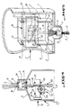
- a delivery device essentially comprises a body 1 forming a reservoir 2 intended to contain any product, such as for example a cosmetic product and consisting of a wall 3 more or less flexible, deformable and preferably elastic 3, on which an external and manual pressure can be exerted along arrow F, so as to actuate means 4 for controlling the delivery of the product, which are housed in the tank 2.
- a product such as for example a cosmetic product and consisting of a wall 3 more or less flexible, deformable and preferably elastic 3, on which an external and manual pressure can be exerted along arrow F, so as to actuate means 4 for controlling the delivery of the product, which are housed in the tank 2.
- the body 1 is provided with a head 5 provided with an orifice 6 for delivering the product, the head 5 being connected to the wall 3 of the reservoir 2 by any suitable means, such as screwing, crimping, or molding in one piece . of the two elements.
- control means 4 are constituted by a sector-shaped part 7 which is articulated in the tank 2, and this on a support 8 secured to the head 5. More specifically, the sector 7 is pivotally mounted at 9, by means of a small axis for example, on the support 8.
- This sector 7 can, in the case of the embodiment of FIG. 3, be formed of two flanges 7a leaving between them a space whose role will be explained later.
- the part 7 cooperates with a rod 10 slidably mounted in the head 5 and carrying a valve 11 secured to one end of said rod and capable of closing the orifice 6.
- the valve 11 may include bristles 12 forming in a way a brush for applying the product contained in the reservoir 2.
- a brush secured to the valve 11 it would be perfectly possible, without departing from the scope of the invention, to use a wick which would be secured either to this valve 11 or to the head 5 as shown in FIG. 1.
- FIG. 3 The embodiment visible in FIG. 3 is substantially identical to that of FIG. 1, except that here, by exerting an external pressure on the side wall 3 of the tank 2, not a push is carried out, but a pull on the rod 10 carrying the valve 11, and this against the force of the spring 15.
- the end 16 of the rod 10 housed in the space between the flanges 7a of the part 7, carries a small axis 17 retained between these flanges.
- one of the tops of the flanges 7a has a beak-shaped part 13 capable of retaining the minor axis 17.
- a stop 18 has been provided on the rod 10 capable of limiting the stroke of this rod in traction, so as to dose a certain quantity of product leaving through the orifice 6 More specifically, this stop 18 may, under the effect of the traction of the rod 10 cooperate with the base 19 for connecting the head 5 to the tank 2, which base has orifices 20 for the passage of the product and a bearing 21 allowing the guided sliding of the rod 10. It will be observed here that the stop 18, by closing off the orifices 20, advantageously plays the role of a means of controlled delivery of the product leaving through said orifices.
- control means 4 for delivering the product contained in the tank 2 essentially comprises a push button 22 disposed inside this tank orthogonally to the axis of the body 1, and meshing with a pinion 23 which is integral with this body and which meshes with a toothing 24 carried by the rod 10 actuating the valve 11.
- the gear-to-gear ratio is chosen appropriately to adjust the stroke of the rod 10.
- the push button 22 By pushing, along arrow F, on the wall 3 of the tank 2, the push button 22 will be actuated which, by means of the pinion 23 will cause the rod 10 to descend, against the force of the return spring 15 , so that the valve 11 will disengage from its seat 14, as can be seen in FIG. 4.
- the spring 15 By releasing the pressure along arrow F, the spring 15 will bring the valve 11 against its seat 14, which will cause the pinion 23 to rotate in the opposite direction, and consequently the push-button 22 to be put back in position near the wall. internal of the reservoir 2, so that the device will be ready for a new delivery of product by re-pressing the side wall of the reservoir according to the arrow F.
- the means 4 for controlling the rod 10 essentially consist of a movable part 26 in the shape of a stirrup or of a U, the base 27 of which is substantially parallel to the wall 3 of the tank 2, and the two branches 28 of which each have a recess 29 forming a ramp 30 cooperating with a small transverse axis 31 secured to the end of the rod 10 opposite to that carrying the valve 11.
- the U-shaped part 26 is slidably mounted by its branches 28, and this orthogonally to the axis of the body 1, in a support 8 having in a way the shape of a polygonal sleeve through which a transverse light 32 is formed. slidingly and guided part 26.
- the part 26 By external pressure on the flexible and deformable wall 3 of the reservoir 2 along the arrow F, as seen in FIG. 5, the part 26 will be actuated transversely, which will cause, thanks to the ramp 30, the displacement of the rod 10 , against the force of the return spring 15, so that the valve 11 will be released from its seat 14, and that the product will be delivered through the orifice 6 of the head 5.
- the material constituting the body of the device can be of any suitable composition such as polyethylene as well as that constituting the various organs of the control mechanism inside the tank, it being understood that in this regard, a synthetic material will be preferred .
- the configuration of the sector-shaped part may be any and appropriate, in particular depending on the viscosity of the product contained in the reservoir. This part may also have any suitable shape at the level of its part which will be in contact with the internal wall of the tank when pressure is exerted on the outside of this tank to deliver product.
- the application end constituted by the brush, the wick or the like can penetrate inside the head 5 during the retraction of the rod 10. This has the advantage of promoting the impregnation of the application end by the product.
- the device according to this invention is particularly suitable for the delivery of viscous liquids, such as for example nail varnish.
- a composite plastic material such as that known under the trade name "SELAR RB” available from KAUTEX WERKE, BONN (RFA) and which is compatible with solvents used in the nail polish formula and which is also impermeable to the vapors of these solvents.
Landscapes
- Containers And Packaging Bodies Having A Special Means To Remove Contents (AREA)
- Coating Apparatus (AREA)
Claims (7)
- Vorrichtung zum Abgeben irgendeines in einem Behälter (2) mit verformbarer Wand (3) enthaltenen Erzeugnisses, welcher einen Teil eines mit einer die Abgabe dieses Erzeugnisses gestattenden verschliessbaren Öffnung (6) versehenen Körpers (1) bildet, wobei Mittel (4) zur Betätigung der Abgabe des Erzeugnisses in dem Behälter (2) untergebracht und durch einen auf die verformbare Wand dieses Behälters ausgeübten äusseren Druck (F) betätigbar sind, dadurch gekennzeichnet, dass die besagten Betätigungsmittel durch einen sektorförmigen Teil (7) gebildet sind, der in dem Behälter (2) an einem mit dem Körper (1) fest verbundenen Halter (8) in gelenkiger Weise (9) angeordnet ist und mit einem Stab (10) zusammenwirkt, der ein mit einem Ende des Stabes (10) fest verbundenes Ventil (11), das fähig ist, die vorgenannte Öffnung (6) zu verschliessen, betätigt, wobei der sektorförmige Teil (7) durch Schub oder durch Zug auf den Stab (10) entgegen der Kraft von wenigstens einer Rückstellfeder (15) wirkt.
- Vorrichtung nach Anspruch 1, dadurch gekennzeichnet, dass der sektorförmige Teil (7) durch zwei etwa parallele Wangen (7a), zwischen welchen ein Ende des vorgenannten Stabes (10) angeordnet ist, gebildet wird.
- Vorrichtung zur Abgabe irgendeines in einem Behälter (2) mit verformbarer Wand (3) enthaltenen Erzeugnisses, der einen Teil eines mit einer die Abgabe dieses Erzeugnisses gestattenden verschliessbaren Öffnung (6) versehenen Körpers (1) bildet, wobei Mittel (4) zur Betätigung der Abgabe des Erzeugnisses in dem Behälter (2) untergebracht und durch einen auf die verformbare Wand dieses Behälters ausgeübten äusseren Druck (F) betätigbar sind, dadurch gekennzeichnet, dass die besagten Betätigungsmittel durch einen innerhalb des Behälters (2) senkrecht zur Achse des Körpers (1) angeordneten Druckknopf (22) gebildet werden, der mit einem Ritzel (23) kämmt, das mit diesem Körper fest verbunden ist und das selber mit einer durch einen Stab (10) getragenen Verzahnung (24) kämmt, der ein Ventil (11), das fähig ist, die Öffnung (6) zu verschliessen, betätigt.
- Vorrichtung zur Abgabe irgendeines in einem Behälter (2) mit verformbarer Wand (3) enthaltenen Erzeugnisses, der einen Teil eines mit einer die Abgabe dieses Erzeugnisses gestattenden verschliessbaren Öffnung (6) versehenen Körpers (1) bildet, wobei Mittel (4) zur Betätigung der Abgabe des Erzeugnisses in dem Behälter (2) untergebracht und durch einen auf die verformbare Wand dieses Behälters ausgeübten äusseren Druck (F) betätigbar sind, dadurch gekennzeichnet, dass die besagten Betätigungsmittel durch ein bügel- bzw. U-förmiges bewegliches Stück (26) gebildet werden, dessen Steg (27) etwa parallel zu der Wandlung (3) des Behälters (2) ist und dessen Schenkel (28) ausgespart sind, um eine mit dem Ende eines zwischen diesen Schenkeln verlaufenden Stabes (10) zusammenwirkende Rampe (30) zu bilden, welcher ein Ventil (11) betätigt, das fähig ist, die Öffnung (6) zu verschliessen.
- Vorrichtung nach Anspruch 4, dadurch gekennzeichnet, dass das U-förmige Stück (26) mit seinen Schenkeln (28) orthogonal zu der Achse des Körpers (1) in einem mit dem Körper (1) fest verbundenen Halter (8) gleitet.
- Vorrichtung nach einem der Ansprüche 1 bis 5, dadurch gekennzeichnet dass der vorgenannte Halter (8) mit einem die vorgenannte Öffnung (6) und das vorgenannte Ventil (11) aufweisenden Kopf (5), in welchem der vorgenannte Stab (10) gleitet, fest verbunden ist.
- Vorrichtung nach einem der vorangehenden Ansprüche, dadurch gekennzeichnet, dass das vorgenannte Ventil einen aus der vorgenannten Öffnung (6) hervorstehenden Pinsel (12) bildende Borsten aufweist.
Applications Claiming Priority (3)
| Application Number | Priority Date | Filing Date | Title |
|---|---|---|---|
| FR8905991 | 1989-05-05 | ||
| FR8905991A FR2646652B1 (fr) | 1989-05-05 | 1989-05-05 | Dispositif de delivrance d'un produit quelconque contenu dans un reservoir a paroi deformable |
| PCT/FR1990/000321 WO1990013234A1 (fr) | 1989-05-05 | 1990-05-04 | Dispositif de delivrance d'un produit quelconque contenu dans un reservoir a paroi deformable |
Publications (2)
| Publication Number | Publication Date |
|---|---|
| EP0471717A1 EP0471717A1 (de) | 1992-02-26 |
| EP0471717B1 true EP0471717B1 (de) | 1994-08-10 |
Family
ID=9381447
Family Applications (1)
| Application Number | Title | Priority Date | Filing Date |
|---|---|---|---|
| EP90907152A Expired - Lifetime EP0471717B1 (de) | 1989-05-05 | 1990-05-04 | Vorrichtung zum abgeben von irgendeinem erzeugnis aus einem behälter mit verformbarer wand |
Country Status (7)
| Country | Link |
|---|---|
| US (1) | US5248212A (de) |
| EP (1) | EP0471717B1 (de) |
| JP (1) | JPH04505115A (de) |
| DE (1) | DE69011517T2 (de) |
| ES (1) | ES2061034T3 (de) |
| FR (1) | FR2646652B1 (de) |
| WO (1) | WO1990013234A1 (de) |
Families Citing this family (10)
| Publication number | Priority date | Publication date | Assignee | Title |
|---|---|---|---|---|
| FR2717352B1 (fr) * | 1994-03-16 | 1996-05-15 | Lvmh Rech | Dispositif applicateur rechargeable d'un produit liquide plus ou moins visqueux. |
| FR2738729B1 (fr) * | 1995-09-15 | 1997-11-28 | Lvmh Rech | Appareil applicateur d'un produit liquide plus ou moins visqueux, tel que vernis a ongle |
| FR2738731B1 (fr) * | 1995-09-15 | 1997-11-28 | Lvmh Rech | Utilisation d'un systeme de commande magnetique dans un dispositif comportant un element actif de maquillage ou de travail |
| US5960802A (en) * | 1995-12-06 | 1999-10-05 | Tmc Kaken Kabushiki Kaisha | Pen-type chemical applicator |
| US6409406B1 (en) | 2001-08-27 | 2002-06-25 | Gilbert Schwartzman | Valved fluid applicator |
| US8870030B2 (en) * | 2011-02-04 | 2014-10-28 | S.C. Johnson & Son, Inc. | Attachment mechanism for a container |
| US8985398B2 (en) | 2011-02-04 | 2015-03-24 | S.C. Johnson & Son, Inc. | Attachment mechanism for a container |
| CN104995100B (zh) * | 2012-12-18 | 2017-05-10 | 株式会社细川洋行 | 单向阀以及带有单向阀的容器 |
| JP6234675B2 (ja) * | 2012-12-18 | 2017-11-22 | 株式会社細川洋行 | 逆止弁付き容器 |
| NL2028243B1 (en) * | 2021-05-19 | 2022-12-05 | Daklapack Europe B V | Assembly of spout and plug element; plug element for connection to a spout; pouch comprising plug element. |
Family Cites Families (9)
| Publication number | Priority date | Publication date | Assignee | Title |
|---|---|---|---|---|
| US172161A (en) * | 1876-01-11 | Improvement in oilers | ||
| US889491A (en) * | 1906-11-28 | 1908-06-02 | Henry A Tellerson | Oil-can. |
| US1033861A (en) * | 1907-03-04 | 1912-07-30 | Oxweld Acetylene Co | Acetylene-gas lamp. |
| US1401180A (en) * | 1920-05-03 | 1921-12-27 | Albert R Nelson | Oil-can |
| GB1087331A (en) * | 1963-08-12 | 1967-10-18 | Chiswick Products Ltd | Improvements in or relating to dispensing devices or applicators for bottles tubes and like containers |
| DE1486315A1 (de) * | 1964-05-22 | 1969-04-30 | Eberspaecher Geb Helms | Gefaessverschluss |
| DE3626622A1 (de) * | 1986-08-06 | 1988-02-18 | Schmidt Feintechnik Gmbh | Geraet zum dosierten ausbringen von fluessigen korrekturmitteln, lacken oder dgl. fluessigkeiten |
| US4867593A (en) * | 1987-01-30 | 1989-09-19 | Pentel Kabushiki Kaisha | Liquid dispenser with valve mechanism and flexible container |
| DE8716466U1 (de) * | 1987-12-14 | 1988-02-18 | Katz, Otto, Dipl.-Ing., 8540 Schwabach | Abgabevorrichtung für Flüssigkeiten |
-
1989
- 1989-05-05 FR FR8905991A patent/FR2646652B1/fr not_active Expired - Lifetime
-
1990
- 1990-05-04 ES ES90907152T patent/ES2061034T3/es not_active Expired - Lifetime
- 1990-05-04 US US07/777,229 patent/US5248212A/en not_active Expired - Fee Related
- 1990-05-04 JP JP2507399A patent/JPH04505115A/ja active Pending
- 1990-05-04 EP EP90907152A patent/EP0471717B1/de not_active Expired - Lifetime
- 1990-05-04 WO PCT/FR1990/000321 patent/WO1990013234A1/fr not_active Ceased
- 1990-05-04 DE DE69011517T patent/DE69011517T2/de not_active Expired - Fee Related
Also Published As
| Publication number | Publication date |
|---|---|
| FR2646652A1 (fr) | 1990-11-09 |
| DE69011517D1 (de) | 1994-09-15 |
| DE69011517T2 (de) | 1995-03-30 |
| JPH04505115A (ja) | 1992-09-10 |
| FR2646652B1 (fr) | 1991-10-04 |
| ES2061034T3 (es) | 1994-12-01 |
| WO1990013234A1 (fr) | 1990-11-15 |
| EP0471717A1 (de) | 1992-02-26 |
| US5248212A (en) | 1993-09-28 |
Similar Documents
| Publication | Publication Date | Title |
|---|---|---|
| EP0553021B1 (de) | Schminkvorrichtung | |
| EP0538349B1 (de) | Auftragsvorrichtung für mehr oder weniger dickflüssige produkte | |
| FR2942781A1 (fr) | Dispositif pour ouvrir et fermer une buse de boitier cosmetique | |
| EP2667976B1 (de) | Spenderkopf für ein flüssiges produkt | |
| EP1462180A2 (de) | Vorrichtung zur wiederholten Abgabe von Mediendosen | |
| EP0471717B1 (de) | Vorrichtung zum abgeben von irgendeinem erzeugnis aus einem behälter mit verformbarer wand | |
| FR2764824A1 (fr) | Applicateur de liquide visqueux | |
| EP0241626A2 (de) | Behälter zur dosierten Ausgabe von flüssigen Produkten | |
| FR2693174A1 (fr) | Perfectionnements aux dispositifs distributeur et doseur de produit. | |
| EP1687097B1 (de) | Pumpe zur abgabe eines fluidprodukts | |
| EP1410730B1 (de) | Vorrichtung mit einem Antrieb eines Stiftes oder eines beweglichen Kolbens in einem Basisteil | |
| EP0482099B1 (de) | Spendervorrichtung für einen produktenthaltenden behälter mit verformbaren wänden | |
| FR2637512A1 (fr) | Dispositif de delivrance automatique d'un produit ou d'un objet quelconque | |
| FR2814727A1 (fr) | Valve destinee a equiper un dispositif pour la distribution sous pression d'un produit, et dispositif ainsi equipe | |
| FR2692040A1 (fr) | Dispositif doseur pour substance fluide. | |
| FR2753060A1 (fr) | Distributeur de produit cosmetique destine au maquillage | |
| EP3426410B1 (de) | Fluidspender mit mitteln zur druckbeaufschlagung einer ausgabepumpe | |
| EP1497039B1 (de) | Abgabepumpe für medien | |
| EP1149775A1 (de) | Aerosolbehälter ausgestattet mit einem verbesserten Ventil | |
| FR3083784A1 (fr) | Dispositif de fixation d'une pompe de distribution de produit sur un flacon et ensembles comprenant ledit dispositif ou des composants dudit dispositif | |
| FR2859464A1 (fr) | Dispositif de distribution a pompe pour un produit fluide, liquide ou pateux | |
| EP1452109B1 (de) | Applikator für ein Produkt, insbesondere für Kosmetik | |
| FR2770109A1 (fr) | Applicateur d'une substance, notamment d'une matiere deodorante | |
| FR2727670A1 (fr) | Dispositif pour prelever dans un recipient une dose d'un produit, notamment cosmetique, et pour appliquer cette dose | |
| EP2062495B1 (de) | System zum Aufbringen eines pastenartigen flüssigen Produkts durch Verdrehen einer flexiblen Verpackungshülle |
Legal Events
| Date | Code | Title | Description |
|---|---|---|---|
| PUAI | Public reference made under article 153(3) epc to a published international application that has entered the european phase |
Free format text: ORIGINAL CODE: 0009012 |
|
| 17P | Request for examination filed |
Effective date: 19911031 |
|
| AK | Designated contracting states |
Kind code of ref document: A1 Designated state(s): DE ES FR GB IT |
|
| 17Q | First examination report despatched |
Effective date: 19930526 |
|
| GRAA | (expected) grant |
Free format text: ORIGINAL CODE: 0009210 |
|
| AK | Designated contracting states |
Kind code of ref document: B1 Designated state(s): DE ES FR GB IT |
|
| REF | Corresponds to: |
Ref document number: 69011517 Country of ref document: DE Date of ref document: 19940915 |
|
| ITF | It: translation for a ep patent filed | ||
| REG | Reference to a national code |
Ref country code: ES Ref legal event code: FG2A Ref document number: 2061034 Country of ref document: ES Kind code of ref document: T3 |
|
| GBT | Gb: translation of ep patent filed (gb section 77(6)(a)/1977) |
Effective date: 19941115 |
|
| PLBE | No opposition filed within time limit |
Free format text: ORIGINAL CODE: 0009261 |
|
| STAA | Information on the status of an ep patent application or granted ep patent |
Free format text: STATUS: NO OPPOSITION FILED WITHIN TIME LIMIT |
|
| 26N | No opposition filed | ||
| PGFP | Annual fee paid to national office [announced via postgrant information from national office to epo] |
Ref country code: GB Payment date: 19970425 Year of fee payment: 8 |
|
| PGFP | Annual fee paid to national office [announced via postgrant information from national office to epo] |
Ref country code: DE Payment date: 19970509 Year of fee payment: 8 |
|
| PGFP | Annual fee paid to national office [announced via postgrant information from national office to epo] |
Ref country code: ES Payment date: 19970528 Year of fee payment: 8 |
|
| PG25 | Lapsed in a contracting state [announced via postgrant information from national office to epo] |
Ref country code: GB Free format text: LAPSE BECAUSE OF NON-PAYMENT OF DUE FEES Effective date: 19980504 |
|
| PG25 | Lapsed in a contracting state [announced via postgrant information from national office to epo] |
Ref country code: ES Free format text: LAPSE BECAUSE OF EXPIRATION OF PROTECTION Effective date: 19980505 |
|
| PGFP | Annual fee paid to national office [announced via postgrant information from national office to epo] |
Ref country code: FR Payment date: 19980528 Year of fee payment: 9 |
|
| GBPC | Gb: european patent ceased through non-payment of renewal fee |
Effective date: 19980504 |
|
| PG25 | Lapsed in a contracting state [announced via postgrant information from national office to epo] |
Ref country code: DE Free format text: LAPSE BECAUSE OF NON-PAYMENT OF DUE FEES Effective date: 19990302 |
|
| PG25 | Lapsed in a contracting state [announced via postgrant information from national office to epo] |
Ref country code: FR Free format text: LAPSE BECAUSE OF NON-PAYMENT OF DUE FEES Effective date: 20000131 |
|
| REG | Reference to a national code |
Ref country code: FR Ref legal event code: ST |
|
| REG | Reference to a national code |
Ref country code: ES Ref legal event code: FD2A Effective date: 20000301 |
|
| PG25 | Lapsed in a contracting state [announced via postgrant information from national office to epo] |
Ref country code: IT Free format text: LAPSE BECAUSE OF NON-PAYMENT OF DUE FEES Effective date: 20050504 |