EP0471748B1 - Accessoire de bicyclette portant un cable antivol - Google Patents
Accessoire de bicyclette portant un cable antivol Download PDFInfo
- Publication number
- EP0471748B1 EP0471748B1 EP90907612A EP90907612A EP0471748B1 EP 0471748 B1 EP0471748 B1 EP 0471748B1 EP 90907612 A EP90907612 A EP 90907612A EP 90907612 A EP90907612 A EP 90907612A EP 0471748 B1 EP0471748 B1 EP 0471748B1
- Authority
- EP
- European Patent Office
- Prior art keywords
- shackle
- coiled
- elongated arm
- elongated
- lid
- Prior art date
- Legal status (The legal status is an assumption and is not a legal conclusion. Google has not performed a legal analysis and makes no representation as to the accuracy of the status listed.)
- Expired - Lifetime
Links
- 230000000903 blocking effect Effects 0.000 claims description 4
- 238000003780 insertion Methods 0.000 claims description 3
- 230000037431 insertion Effects 0.000 claims description 3
- 210000005069 ears Anatomy 0.000 description 3
- 230000002452 interceptive effect Effects 0.000 description 3
- 238000004519 manufacturing process Methods 0.000 description 2
- 238000000034 method Methods 0.000 description 2
- 230000006835 compression Effects 0.000 description 1
- 238000007906 compression Methods 0.000 description 1
- 230000006870 function Effects 0.000 description 1
- 230000005484 gravity Effects 0.000 description 1
- 230000003100 immobilizing effect Effects 0.000 description 1
- 238000002347 injection Methods 0.000 description 1
- 239000007924 injection Substances 0.000 description 1
- 239000000463 material Substances 0.000 description 1
- 238000001228 spectrum Methods 0.000 description 1
- 229920001169 thermoplastic Polymers 0.000 description 1
- 239000012815 thermoplastic material Substances 0.000 description 1
- 239000004416 thermosoftening plastic Substances 0.000 description 1
Images
Classifications
-
- B—PERFORMING OPERATIONS; TRANSPORTING
- B62—LAND VEHICLES FOR TRAVELLING OTHERWISE THAN ON RAILS
- B62J—CYCLE SADDLES OR SEATS; AUXILIARY DEVICES OR ACCESSORIES SPECIALLY ADAPTED TO CYCLES AND NOT OTHERWISE PROVIDED FOR, e.g. ARTICLE CARRIERS OR CYCLE PROTECTORS
- B62J11/00—Supporting arrangements specially adapted for fastening specific devices to cycles, e.g. supports for attaching maps
-
- B—PERFORMING OPERATIONS; TRANSPORTING
- B62—LAND VEHICLES FOR TRAVELLING OTHERWISE THAN ON RAILS
- B62H—CYCLE STANDS; SUPPORTS OR HOLDERS FOR PARKING OR STORING CYCLES; APPLIANCES PREVENTING OR INDICATING UNAUTHORIZED USE OR THEFT OF CYCLES; LOCKS INTEGRAL WITH CYCLES; DEVICES FOR LEARNING TO RIDE CYCLES
- B62H5/00—Appliances preventing or indicating unauthorised use or theft of cycles; Locks integral with cycles
- B62H5/003—Appliances preventing or indicating unauthorised use or theft of cycles; Locks integral with cycles using chains or cables
-
- Y—GENERAL TAGGING OF NEW TECHNOLOGICAL DEVELOPMENTS; GENERAL TAGGING OF CROSS-SECTIONAL TECHNOLOGIES SPANNING OVER SEVERAL SECTIONS OF THE IPC; TECHNICAL SUBJECTS COVERED BY FORMER USPC CROSS-REFERENCE ART COLLECTIONS [XRACs] AND DIGESTS
- Y10—TECHNICAL SUBJECTS COVERED BY FORMER USPC
- Y10S—TECHNICAL SUBJECTS COVERED BY FORMER USPC CROSS-REFERENCE ART COLLECTIONS [XRACs] AND DIGESTS
- Y10S224/00—Package and article carriers
- Y10S224/935—Carrier for cycle lock
Definitions
- the present invention generally relates to an accessory for a bicycle or similar vehicle and, more particularly, to a carrier accessory for holding a coiled shackle, with or without a padlock, on a bicycle.
- the cable, and especially the helical coiled cable, combined with a padlock has enjoyed great popularity with the bicycling public for use in securing a bicycle against theft.
- the best method for carrying such a chain or cable while the bicycle is being ridden is left to the imagination of the rider.
- Many riders attach the ends of their chains or cables to the underside of their bicycle seat, or wrap the shackle around the post under the bicycle seat, or around the bicycle frame.
- Other riders wrap the chain or cable on the handlebars of their bicycles, or carry them separately in a bag or on their person.
- U.S. Patent 3,848,783 there is described a bracket mounted to a tubular frame member of the bicycle having a detent latching means for attaching it to the frame member and a cross member having pleat-like folds at its outboard ends to hold the flexible cable or chain in a coil-like manner.
- Another object is to provide such a carrier accessory which will secure the coiled shackle and any padlock against movement, thereby eliminating the potential for the cable to interfere with the use or operation of the bicycle or to damage the bicycle.
- a coiled shackle carrier accessory having a means, such as a clamp, for attaching the carrier accessory to a bicycle or the like, and means for carrying a coiled shackle, said carrying means being connected and carried by said attaching means.
- These new features include a first elongated arm with an upper surface adapted to receive and support the coiled shackle. These new features also include means for releasably securing the coiled shackle to the upper surface of the first elongated arm being also connected to and carried by the attaching means and including a second elongated arm extending substantially along, but spaced from, the first elongated arm to form therewith a clip adapted to receive and secure the coiled shackle between the first and second elongated arms.
- These new features further include means for releasably clamping the first and second elongated arms toward one another to secure the coiled shackle therebetween.
- the clamping means is a hinged lid attached to the distal end of one of the elongated arms. A portion of the hinged lid and a portion of the distal end of the other elongated arm form a locking arrangement.
- the hinged lid When the hinged lid is unlocked and moved to an open position the coiled shackle may be inserted between, or removed from between, the elongated arms of the carrier accessory. When a coiled shackle is inserted between the elongated arms of the carrier accessory, the elongated arms may then be locked together by the lid to form a closed, and normally tightened, carrier accessory for the coiled shackle, with or without a padlock. When the hinged lid is placed in a closed position and locked, with appropriately selected dimensions the coiled shackle, and any associated padlock, are squeezed between the elongated arms and thereby secured against movement.
- the new features still further include means for blocking inadvertent removal of the coiled shackle from between the first and second elongated arms.
- the means for blocking inadvertent removal of the coiled shackle is a projection which is carried by the first elongated arm and extends upwardly for a distance sufficient to substantially block inadvertent removal of the coiled shackle from the first elongated arm.
- the present invention discloses and provides a carrier accessory for securing a shackle, such as a helical coiled security cable, with or without a padlock, to a bicycle.
- the carrier accessory is simultaneously lightweight, quick and efficient to operate, yet capable of carrying and securing the coiled shackle, with or without a padlock.
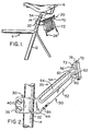
- Fig. 1 is a side elevational view of a portion of a bicycle showing a carrier accessory of the present invention mounted on a seat post of the bicycle and carrying a coiled shackle and padlock.
- Fig. 2 is an enlarged side elevational view of the carrier accessory mounted on a portion of the seat post of the bicycle, with a hinged lid of the carrier accessory in a closed and locked position.
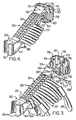
- Fig. 3 is an exploded fragmentary front perspective view of the carrier accessory with the padlock and the coils of the shackle shown broken away.
- Fig. 4 is a fragmentary front perspective view of the carrier accessory showing the hinged lid in an engaged position, and with a coiled shackle secured on the carrier accessory.
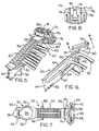
- Fig. 5 is a fragmentary front perspective view of the carrier accessory showing the hinged lid in a disengaged position, and with a coiled shackle loosely held by the carrier accessory.
- Fig. 6 is a is a fragmentary side elevational view of the carrier assembly with the hinged lid in a fully opened and stable raised position with a coiled shackle being placed upon or being removed from the carrier accessory.
- Fig. 7 is a top plan view of the carrier accessory.
- Fig. 8 is an elevational view of the hinged lid taken along line 8--8 of Fig. 6.
- a portion of a bicycle 11 is shown having a frame 12 with a seat post 14 secured to the frame 12 and a seat 16 mounted on seat post 14.
- a cable carrier accessory 20 of the present invention is mounted on the seat post 14 so as to extend towards the rear of the bicycle.
- the carrier accessory 20 is illustrated in various modes of use with a coiled shackle 22 and a padlock 24 including a shackle portion 26 carried thereby.
- the illustrated shackle 22 is a helical coiled cable, but other types of coilable shackles may be carried in an improved manner by the carrier accessory 20 of the present invention.
- Shackle 22, as illustrated in FIG. 3, includes eyelets 28 at the opposite ends thereof for receiving padlock 24 therethrough when shackle 22 is used to secure a bicycle frame 12 to a stationary object, such as a bicycle stand, post, tree, or the like.
- the accessory carrier 20 includes a post clamp 30 as one mechanism for attaching the carrier accessory 20 to cylindrical seat post 14.
- Clamp 30 includes two expandable semi-circular arms 32 defining an annular substantially circular opening 34, as shown in FIG. 7.
- Circular opening 34 is shaped and designed to receive cylindrical post 14, or some other cylindrical portion of bicycle frame 12 therein.
- Extended portions 36 of semi-circular arms 32 include apertures, not visible, for receiving threaded bolts 40 therethrough.
- Each bolt 40 is secured by nut 42, as shown in FIG. 7, which nuts 42 allow the tightening or loosening of clamp 30.
- bolts 40 can then be removed, thereby allowing semi-circular arms 32 to be spread apart and expanded to allow post 14 or some other portion of bicycle frame 12 to be received within opening 34.
- Bolts 40 can then be inserted through the apertures in the extended portions 36 of semi-circular arms 32, connected to nuts 42, and tightened, thus securing the carrier accessory 20 to the seat post 14, or to some other portion of bicycle frame 12. Removal of carrier accessory 20 can be accomplished by reversing these steps.
- carrier accessory 20 also includes a web portion 40 which extends to the left of clamp 30 and a clip 50 connected to and extending from the right of the web portion 40 and angling upwardly when the accessory 20 is attached to seat post 14.
- Clip 50 includes a lower elongated arm 52 which is designed to receive the coiled shackle 22 on its upper surface and an upper elongated arm 54 extending generally parallel to the lower elongated arm 52.
- the upper arm 54 terminates in an outer or distal end 56, opposed to clamp 30, and having an aperture 58 defined therethrough, as shown in FIG. 3.
- the lower elongated arm 52 is disposed in a parallel spaced relationship from upper elongated arm 54 to define a space 64 between them which is dimensioned to receive the coils of the shackle 22 therein.
- Web portion 44 and lower and upper elongated arms 52, 54 forming clip 50 together with clamp 30 are preferably in the form of an integrally-connected one-piece structure.
- lower and upper elongated arms 52, 54 extend outwardly in cantilevered fashion from clamp 30 via web portion 44.
- the upper elongated arm 54 can flex toward and away from lower elongated arm 52. Such flexing permits increase of the height of space 64 between them for facilitating insertion or removal of shackle 22.
- the outer or distal end of upper elongated arm 54 includes a node or protrusion 59, while the lower elongated arm 52 has a discontinuity at its outer or distal end which defines a shoulder or keeper 62.
- the clip 50 is angled upwardly so that the coils of the shackle 22 can be easily gravity-fed into space 64 of carrier accessory 20.
- a locking lid 70 is hingedly attached to the outer end 56 of upper arm 54 using a hinge pin 72.
- the pin 72 is received through apertures 74 defined in a pair of mounting brackets 76 which are, in turn, attached to a back side 78 of lid 70.
- a clasp or hook or finger 80 carried by the back side 78 of lid 70 is a clasp or hook or finger 80 used for releasable locking engagement with shoulder 62 carried by lower elongated arm 52. Shoulder 62 and finger 80 are so dimensioned and designed that they snap into latching or locking engagement when the lid 70 is forced to rotate downward into a closed and locked position as shown in FIGS. 2 and 4.
- the back side 78 of the hinged lid 70 also has a recess 81.
- node 59 makes a releasable snap fit connection with recess 81, thereby positioning and retaining hinged lid 70 in a stable open position until the user urges it downwardly, out of that position, for example, to close the carrier accessory 20.
- node 59 rides against the back side 78 of lid 70, much as a cam would guide a cam follower, to thereby urge lid 70 into a somewhat tensioned and stable position along its arc of motion.
- a trap or stop 82 is formed integral with and extends upwardly from the upper surface of lower elongated arm 52 adjacent its distal end. Should lid 70 be inadvertently left open after a coiled shackle 22 is placed into space 64, as depicted in FIGS. 5 and 6, and the bicycle be ridden with lid 70 unlatched, trap 82 will help to prevent shackle 22 from inadvertently bouncing out of carrier accessory 20 and becoming lost. Trap 82 also serves to isolate shackle 22 from upper elongated arm 54, thereby preventing the shackle 22 from interfering with the closure of hinged lid 70.
- upper elongated arm 54 is sufficiently flexible that it may be raised slightly, thereby allowing the coils of the shackle 22 to pass over the top of trap 82 so that they may be easily received in space 64.
- a pair of outwardly extending ears 86 are attached to opposite sides of lower elongated arm 52.
- FIG. 3 when shackle portion 26 of padlock 24 is received at the lower end of space 64, between lower and upper elongated arms 52, 54, a portion of padlock shackle 26 rests against ears 86. Ears 86 fix the position of padlock shackle 26, and thus of padlock 24 on the carrier accessory 20 so that padlock 24 is kept away from bicycle frame 12, thereby preventing possible contact of padlock 24 with the frame.
- carrier accessory 20 carries shackle 22 and any padlock 24 upwardly and rearwardly from seat post 14, or any other portion of frame 12 which substantially eliminates any chance of their interfering with the operation of the bicycle.
- FIG. 3 illustrates carrier accessory 20 with hinged lid 70 positioned for attachment to outer or distal end 56 of the upper elongated arm 54 of clip 50.
- aperture 58 through distal end 56 of upper elongated arm 54 is received between the mounting brackets 76 on back side 78 of lid 70, and hinge pin 72 is inserted through the apertures 74 and 58.
- lid 70 being rotatably connected to the distal end 56 of upper elongated arm 54.
- Pin 72 has an enlarged head 88 at one end and a split at the other end which defines a pair of compressible lips 90. Lips 90 can be compressed when inserting them through apertures 74 and 58, and then allowed to expand outward when insertion is completed. In this manner, the pin 72 is secured in place and lid 70 is pivotally secured to distal end 56 of upper elongated arm 54.
- FIG. 4 shows carrier accessory 20 with hinged lid 70 closed and locked or latched by the action of finger 80 against shoulder 62, and with the coils of shackle 22 secured between lower and upper elongated arms 52, 54.
- the space 64 between the elongated arms 52, 54 is such that when a shackle of standard diameter is placed in the space 64, and hinged lid 70 is closed and latched, as shown in FIG. 4, shackle 22 is actually squeezed by elongated arms 52, 54, thereby immobilizing the shackle 22 and securing it in place. While not shown, this will normally cause some slight bowing of the portion of upper elongated arm 54 which is adjacent to distal end 56.
- FIG. 5 shows finger 80 of hinged lid 70 just released from shoulder 62, and the coils of shackle 22 released from compression between elongated arms 52, 54.
- FIG. 6 illustrates hinged lid 70 in a completely raised and open position with a portion of the coils of shackle 22 being either removed from or placed into space 64 of clip 50.
- FIG. 7 illustrates the carrier accessory 20 with bolt 40 and nut 42 secured to the post clamp 30. Also, at a front side 94 of the hinged lid 70 is carried a plurality of stand-off fingers 96 for receiving a light reflector 98 therebetween. When lid 70 is in a closed position, as shown in FIGS. 1, 2 and 4, reflector 98 is in a substantially vertical position for reflecting light directed and received at the rear of bicycle 11. Light reflector 98 provides an added safety feature to carrier accessory 20 for the operator of the bicycle 11 during nighttime riding conditions.
- FIG. 8 illustrates the structure and relationship of apertures 74 carried by mounting brackets 76 to the recess 81.
- carrier accessory 20 is shown, for example in FIGS. 1 and 2, attached to seat post 14 of the bicycle frame 12, it should be kept in mind that carrier accessory 20 can serve its function of carrying a coiled shackle equally well when attached to other portions of a bicycle, or on equivalent types of equipment or vehicles requiring the use of a security shackle.
- carrier accessory 20 is adapted for holding either the coils of any flexible shackle, including chains or cables, and also various lock structures, such as padlocks, either separately or in combination.
- Carrier accessory 20 may be made of a variety of materials, including but not limited to thermoplastic materials. If produced of thermoplastic, the carrier accessory is designed so that it may be easily injection molded for mass production.
Landscapes
- Engineering & Computer Science (AREA)
- Mechanical Engineering (AREA)
- Fittings On The Vehicle Exterior For Carrying Loads, And Devices For Holding Or Mounting Articles (AREA)
- Clamps And Clips (AREA)
- Professional, Industrial, Or Sporting Protective Garments (AREA)
Abstract
Claims (10)
- Accessoire (20) pour fixer une boucle ou un câble antivol enroulé (22) à une bicyclette (11) et comportant des moyens (30) d'attache de l'accessoire (20) à la bicyclette (11) et des moyens de support d'un câble enroulé (22), lesdits moyens de support étant reliés aux dits moyens d'attache (30) et portés par ceux-ci, l'accessoire (20) étant caractérisé par :
un premier bras allongé (52) ayant une surface supérieure prévue pour recevoir et supporter le câble enroulé (22) ; et
des moyens de fixation libérable du câble enroulé (22) à ladite surface supérieure dudit premier bras allongé (52), lesdits moyens de fixation étant reliés aux dits moyens d'attache (30) et portés par ces derniers et comprenant un deuxième bras allongé (54) qui s'étend sensiblement le long mais à une certaine distance dudit premier bras allongé (52) de façon à définir avec celui-ci une pince (50) qui peut recevoir et retenir le câble enroulé (22) entre lesdits premier et deuxième bras allongés (52,54). - Accessoire (20) suivant la revendication 1, dans lequel lesdits moyens d'attache (30) comprennent un collier, ladite pince (50) s'étendant vers l'extérieur en porte-à-faux à partir dudit collier (30), ladite pince (50) et ledit collier (30) constituant une structure solidaire monobloc.
- Accessoire (20) suivant la revendication 1, dans lequel lesdits premier et deuxième bras allongés (52, 54) sont suffisamment espacés l'un de l'autre pour recevoir entre eux un câble enroulé (22), ledit premier bras allongé (52) étant prévu pour recevoir et porter le câble enroulé (22) sur sadite surface supérieure, ledit deuxième bras allongé (54) pouvant fléchir de manière à se rapprocher et s'éloigner dudit premier bras allongé (52) respectivement pour presser et pour bloquer le câble enroulé (22) contre ladite surface supérieure dudit premier bras allongé (52), et pour augmenter la hauteur de l'espace entre lesdits bras allongés (52,54) afin de faciliter l'insertion et l'enlèvement du câble enroulé (22).
- Accessoire (20) suivant la revendication 1, caractérisé en outre par :
des moyens (70) pour presser de façon libérable ledit deuxième bras allongé (54) vers ledit premier bras allongé (52), afin de fixer le câble enroulé (22) à la dite surface supérieure dudit premier bras allongé (52). - Accessoire (20) suivant la revendication 4, dans lequel lesdits moyens (70) pour presser de façon libérable ledit deuxième bras allongé (54) vers ledit premier bras allongé (52) comprennent un couvercle de verrouillage relié de façon pivotante à une extrémité extérieure d'un desdits bras allongés (52,54) et verrouillable de façon libérable à l'extrémité extérieure de l'autre desdits bras allongés (52,54), ledit couvercle (70) étant déplaçable de façon pivotante entre une position fermée, dans laquelle ledit couvercle (70) est verrouillé à ladite extrémité extérieure dudit autre bras allongé (52,54) et empêche l'entrée et la sortie dans et hors de l'espace défini entre lesdits bras allongés (52,54), et une position ouverte dans laquelle ledit couvercle (70) est déverrouillé de ladite extrémité extérieure dudit autre bras allongé (52,54) et libère l'entrée et la sortie dans et hors de l'espace défini entre lesdits bras allongés (52,54).
- Accessoire (20) suivant la revendication 5, dans lequel le verrouillage dudit couvercle (70) avec la dite extrémité extérieure dudit autre bras allongé (52, 54) s'effectue au moyen d'un doigt (80) prévu sur l'un dudit couvercle (70) et dudit autre bras allongé (52,54), qui vient en prise avec un épaulement (62) prévu sur l'autre dudit couvercle (70) et dudit autre bras allongé (52, 54).
- Accessoire (20) suivant la revendication 6, dans lequel ledit couvercle (70) et ledit premier bras allongé (52,54) comportent des moyens coopérants (59,81) aptes à retenir ledit couvercle (70) dans une position stable lorsque ledit couvercle (70) est ouvert d'une quantité suffisante pour permettre de placer un câble enroulé (22) entre lesdits bras allongés (52,54) ou de l'en retirer.
- Accessoire (20) suivant la revendication 7, dans lequel lesdits moyens coopérants (59,81) comprennent un bossage (59) défini sur ladite extrémité extérieure dudit premier bras allongé (52,54) et un évidement (81) défini dans ledit couvercle (70) à une position telle qu'il peut recevoir ledit bossage (59) et retenir ainsi ledit couvercle (70) lorsque ledit couvercle (70) est ouvert de la quantité suffisante pour permettre de placer le câble enroulé (22) entre lesdits bras allongés (52,54) ou de l'en retirer.
- Accessoire (20) suivant la revendication 1, caractérisé en outre par :
des moyens prévus sur un premier desdits bras allongés (52,54) pour empêcher l'enlèvement accidentel d'un câble enroulé (22) d'entre lesdits bras allongés (52, 54). - Accessoire (20) suivant la revendication 9, dans lequel lesdits moyens pour empêcher l'enlèvement accidentel d'un câble enroulé (22) comprennent une saillie (82) formée sur une extrémité extérieure dudit premier bras allongé (52) et s'étendant vers le haut sur une distance suffisante pour empêcher sensiblement la sortie accidentelle du câble enroulé (22) dudit premier bras allongé (52).
Applications Claiming Priority (3)
| Application Number | Priority Date | Filing Date | Title |
|---|---|---|---|
| US349401 | 1982-02-16 | ||
| US07/349,401 US4966382A (en) | 1989-05-08 | 1989-05-08 | Bicycle accessory for carrying a shackle |
| PCT/US1990/002500 WO1990013469A1 (fr) | 1989-05-08 | 1990-05-04 | Accessoire de bicyclette portant un cable antivol |
Publications (3)
| Publication Number | Publication Date |
|---|---|
| EP0471748A1 EP0471748A1 (fr) | 1992-02-26 |
| EP0471748A4 EP0471748A4 (en) | 1992-06-03 |
| EP0471748B1 true EP0471748B1 (fr) | 1994-07-27 |
Family
ID=23372247
Family Applications (1)
| Application Number | Title | Priority Date | Filing Date |
|---|---|---|---|
| EP90907612A Expired - Lifetime EP0471748B1 (fr) | 1989-05-08 | 1990-05-04 | Accessoire de bicyclette portant un cable antivol |
Country Status (7)
| Country | Link |
|---|---|
| US (1) | US4966382A (fr) |
| EP (1) | EP0471748B1 (fr) |
| JP (1) | JPH04504990A (fr) |
| AU (1) | AU643945B2 (fr) |
| CA (1) | CA2055458A1 (fr) |
| DE (1) | DE69011105T2 (fr) |
| WO (1) | WO1990013469A1 (fr) |
Families Citing this family (23)
| Publication number | Priority date | Publication date | Assignee | Title |
|---|---|---|---|---|
| US5167353A (en) * | 1990-03-27 | 1992-12-01 | Hughes Jack I | "U" post bracket for bicycles |
| US5251464A (en) * | 1992-09-03 | 1993-10-12 | Robert Halter | Bicycle lock with storable reel cable |
| US5380061A (en) * | 1993-07-06 | 1995-01-10 | Pendleton; Robert C. | Bicycle seat security ring |
| US5575443A (en) * | 1994-10-04 | 1996-11-19 | Honeycutt; Jay W. | Quick release accessory mount on a bicycle |
| US5709113A (en) * | 1996-03-20 | 1998-01-20 | Winner International Royalty Corporation | Self-storing security device |
| US6431422B1 (en) | 2001-03-03 | 2002-08-13 | David B. Moore | Bicycle accessory mounting apparatus |
| US6557808B1 (en) * | 2002-02-13 | 2003-05-06 | Renny Tse-Haw Ling | Two-piece detachable holder |
| US20040211804A1 (en) * | 2003-04-24 | 2004-10-28 | Chian-Yi Lee | Holding dock structure for a steel cable shackle of bicycles |
| US7311233B2 (en) * | 2004-12-13 | 2007-12-25 | Vulcan Sports Co., Ltd. | Bicycle lock holding apparatus |
| US20070284497A1 (en) * | 2006-03-31 | 2007-12-13 | John Naccarato | Equipment mounting device |
| US20080251555A1 (en) * | 2007-04-16 | 2008-10-16 | Andrews Mark A | Carbon fiber accessory mounting bracket |
| US20080276664A1 (en) * | 2007-05-11 | 2008-11-13 | Vulcan Sports Co., Ltd. | Steel cable fastenable to a lock |
| US20090091100A1 (en) * | 2007-10-05 | 2009-04-09 | Barraza Rick D | Bicycle tow device for skater |
| US9079626B2 (en) | 2011-05-25 | 2015-07-14 | Robert David Zuraski | Portable lock mounting assemblies |
| EP3354546B1 (fr) | 2011-05-25 | 2020-12-23 | Schlage Lock Company LLC | Ensembles de montage de verrou pour des dispositifs de transport |
| GB2495482B (en) * | 2011-10-05 | 2016-02-03 | Patrick Elson | Cycle accessory |
| US9302725B2 (en) * | 2013-03-14 | 2016-04-05 | Bell Sports, Inc. | Locking rack system for bicycles |
| US9694867B2 (en) * | 2013-03-14 | 2017-07-04 | Bell Sports, Inc. | Locking rack system for bicycles |
| US9095973B2 (en) * | 2013-03-15 | 2015-08-04 | Everlast Climbing Industries, Inc. | Bicycle service kits |
| DE102015109860A1 (de) * | 2015-06-19 | 2016-12-22 | ABUS August Bremicker Söhne KG | Halterung |
| USD893285S1 (en) | 2019-01-25 | 2020-08-18 | Bup Labs, LLC | Mount apparatus |
| USD902014S1 (en) | 2019-01-25 | 2020-11-17 | Bup Labs, LLC | Mount apparatus |
| USD1107538S1 (en) | 2023-01-06 | 2025-12-30 | Gary Truesdale | Multiple magnet post mount |
Family Cites Families (7)
| Publication number | Priority date | Publication date | Assignee | Title |
|---|---|---|---|---|
| CH238079A (de) * | 1943-11-02 | 1945-06-15 | Ceresola Medicus | Traggriff an Fahrrädern. |
| US3848783A (en) * | 1973-04-12 | 1974-11-19 | Fort Lock Corp | Bicycle lock carrying bracket |
| US3910602A (en) * | 1974-04-12 | 1975-10-07 | Henry Lindner | Means for storing bicycle security cable |
| US4028916A (en) * | 1976-04-13 | 1977-06-14 | Pender David R | Lock for bicycles and the like |
| US4284289A (en) * | 1979-07-16 | 1981-08-18 | Loux Edwin E | Device for supporting bicycle security chains and cables |
| US4404822A (en) * | 1981-05-18 | 1983-09-20 | Green Leonard O | Pre-coiled cable-lock device |
| WO1983000354A1 (fr) * | 1981-07-20 | 1983-02-03 | Burnett, Arthur, A. | Systeme de stockage et de verrouillage a chaine |
-
1989
- 1989-05-08 US US07/349,401 patent/US4966382A/en not_active Expired - Lifetime
-
1990
- 1990-05-04 JP JP2507580A patent/JPH04504990A/ja active Pending
- 1990-05-04 DE DE69011105T patent/DE69011105T2/de not_active Expired - Fee Related
- 1990-05-04 CA CA002055458A patent/CA2055458A1/fr not_active Abandoned
- 1990-05-04 AU AU56368/90A patent/AU643945B2/en not_active Ceased
- 1990-05-04 WO PCT/US1990/002500 patent/WO1990013469A1/fr not_active Ceased
- 1990-05-04 EP EP90907612A patent/EP0471748B1/fr not_active Expired - Lifetime
Also Published As
| Publication number | Publication date |
|---|---|
| EP0471748A1 (fr) | 1992-02-26 |
| DE69011105T2 (de) | 1994-11-17 |
| US4966382A (en) | 1990-10-30 |
| CA2055458A1 (fr) | 1990-11-09 |
| AU643945B2 (en) | 1993-12-02 |
| EP0471748A4 (en) | 1992-06-03 |
| AU5636890A (en) | 1990-11-29 |
| WO1990013469A1 (fr) | 1990-11-15 |
| DE69011105D1 (de) | 1994-09-01 |
| JPH04504990A (ja) | 1992-09-03 |
Similar Documents
| Publication | Publication Date | Title |
|---|---|---|
| US4966382A (en) | Bicycle accessory for carrying a shackle | |
| US4404822A (en) | Pre-coiled cable-lock device | |
| US6354476B1 (en) | Snap-on motorcycle luggage | |
| US5291765A (en) | Bicycle lock bracket | |
| US4186576A (en) | Vehicle locking device | |
| US4676080A (en) | Locking article for cycle accessories | |
| US3981166A (en) | Easily attached bicycle locking apparatus | |
| US6595031B2 (en) | Retaining device for personal vehicle with handlebars | |
| US4155231A (en) | Bicycle lock and bracket | |
| US5464135A (en) | High performance lock mount and method | |
| US3855825A (en) | Bicycle lock | |
| US4823568A (en) | Anti-theft apparatus for a riding saddle | |
| US4188808A (en) | Bicycle lock | |
| US6536246B2 (en) | Retaining device for personal vehicle with handlebars | |
| US9694867B2 (en) | Locking rack system for bicycles | |
| US4920772A (en) | Bicycle lock | |
| US4869453A (en) | Bicycle stand and anti-theft device | |
| WO1992002400A1 (fr) | Dispositif antivol pour bicyclette | |
| EP0337552A1 (fr) | Porte-bagages avec fermeture à anse détachable | |
| US7076978B2 (en) | Anti-theft apparatus | |
| US4971345A (en) | Security device for bicycle components | |
| US20030145928A1 (en) | Golf bag security device | |
| US5339610A (en) | Anti-theft apparatus for riding saddles | |
| US5730012A (en) | Bicycle sprocket lock | |
| WO2002004280A1 (fr) | Mise a l'attache de bicyclettes et analogue pour les proteger du vol |
Legal Events
| Date | Code | Title | Description |
|---|---|---|---|
| PUAI | Public reference made under article 153(3) epc to a published international application that has entered the european phase |
Free format text: ORIGINAL CODE: 0009012 |
|
| 17P | Request for examination filed |
Effective date: 19911107 |
|
| AK | Designated contracting states |
Kind code of ref document: A1 Designated state(s): DE FR GB IT |
|
| A4 | Supplementary search report drawn up and despatched |
Effective date: 19920421 |
|
| AK | Designated contracting states |
Kind code of ref document: A4 Designated state(s): DE FR GB IT |
|
| 17Q | First examination report despatched |
Effective date: 19931018 |
|
| GRAA | (expected) grant |
Free format text: ORIGINAL CODE: 0009210 |
|
| ITF | It: translation for a ep patent filed | ||
| AK | Designated contracting states |
Kind code of ref document: B1 Designated state(s): DE FR GB IT |
|
| REF | Corresponds to: |
Ref document number: 69011105 Country of ref document: DE Date of ref document: 19940901 |
|
| ET | Fr: translation filed | ||
| PLBE | No opposition filed within time limit |
Free format text: ORIGINAL CODE: 0009261 |
|
| STAA | Information on the status of an ep patent application or granted ep patent |
Free format text: STATUS: NO OPPOSITION FILED WITHIN TIME LIMIT |
|
| 26N | No opposition filed | ||
| PGFP | Annual fee paid to national office [announced via postgrant information from national office to epo] |
Ref country code: GB Payment date: 19970428 Year of fee payment: 8 |
|
| PGFP | Annual fee paid to national office [announced via postgrant information from national office to epo] |
Ref country code: FR Payment date: 19970512 Year of fee payment: 8 |
|
| PG25 | Lapsed in a contracting state [announced via postgrant information from national office to epo] |
Ref country code: GB Free format text: LAPSE BECAUSE OF NON-PAYMENT OF DUE FEES Effective date: 19980504 |
|
| PG25 | Lapsed in a contracting state [announced via postgrant information from national office to epo] |
Ref country code: FR Free format text: LAPSE BECAUSE OF NON-PAYMENT OF DUE FEES Effective date: 19980531 |
|
| PGFP | Annual fee paid to national office [announced via postgrant information from national office to epo] |
Ref country code: DE Payment date: 19980619 Year of fee payment: 9 |
|
| GBPC | Gb: european patent ceased through non-payment of renewal fee |
Effective date: 19980504 |
|
| REG | Reference to a national code |
Ref country code: FR Ref legal event code: ST |
|
| PG25 | Lapsed in a contracting state [announced via postgrant information from national office to epo] |
Ref country code: DE Free format text: LAPSE BECAUSE OF NON-PAYMENT OF DUE FEES Effective date: 20000301 |
|
| PG25 | Lapsed in a contracting state [announced via postgrant information from national office to epo] |
Ref country code: IT Free format text: LAPSE BECAUSE OF NON-PAYMENT OF DUE FEES Effective date: 20050504 |