EP0471920B1 - Compensateur de recul pour canon à gros calibre - Google Patents
Compensateur de recul pour canon à gros calibre Download PDFInfo
- Publication number
- EP0471920B1 EP0471920B1 EP91105675A EP91105675A EP0471920B1 EP 0471920 B1 EP0471920 B1 EP 0471920B1 EP 91105675 A EP91105675 A EP 91105675A EP 91105675 A EP91105675 A EP 91105675A EP 0471920 B1 EP0471920 B1 EP 0471920B1
- Authority
- EP
- European Patent Office
- Prior art keywords
- muzzle brake
- barrel
- muzzle
- brake
- accordance
- Prior art date
- Legal status (The legal status is an assumption and is not a legal conclusion. Google has not performed a legal analysis and makes no representation as to the accuracy of the status listed.)
- Expired - Lifetime
Links
- 230000000694 effects Effects 0.000 claims description 5
- 238000007789 sealing Methods 0.000 claims description 5
- 239000000463 material Substances 0.000 claims description 3
- 239000004429 Calibre Substances 0.000 claims 1
- 239000007789 gas Substances 0.000 description 27
- 238000005260 corrosion Methods 0.000 description 4
- 230000007797 corrosion Effects 0.000 description 4
- 239000000843 powder Substances 0.000 description 4
- 229920001971 elastomer Polymers 0.000 description 2
- 239000000806 elastomer Substances 0.000 description 2
- 238000010304 firing Methods 0.000 description 2
- 230000007704 transition Effects 0.000 description 2
- XLYOFNOQVPJJNP-UHFFFAOYSA-N water Substances O XLYOFNOQVPJJNP-UHFFFAOYSA-N 0.000 description 2
- 229910000831 Steel Inorganic materials 0.000 description 1
- 238000009825 accumulation Methods 0.000 description 1
- 238000010276 construction Methods 0.000 description 1
- 238000005516 engineering process Methods 0.000 description 1
- 230000002349 favourable effect Effects 0.000 description 1
- 238000000034 method Methods 0.000 description 1
- 230000035515 penetration Effects 0.000 description 1
- 230000008092 positive effect Effects 0.000 description 1
- 239000010959 steel Substances 0.000 description 1
Images
Classifications
-
- F—MECHANICAL ENGINEERING; LIGHTING; HEATING; WEAPONS; BLASTING
- F41—WEAPONS
- F41A—FUNCTIONAL FEATURES OR DETAILS COMMON TO BOTH SMALLARMS AND ORDNANCE, e.g. CANNONS; MOUNTINGS FOR SMALLARMS OR ORDNANCE
- F41A21/00—Barrels; Gun tubes; Muzzle attachments; Barrel mounting means
- F41A21/30—Silencers
-
- F—MECHANICAL ENGINEERING; LIGHTING; HEATING; WEAPONS; BLASTING
- F41—WEAPONS
- F41A—FUNCTIONAL FEATURES OR DETAILS COMMON TO BOTH SMALLARMS AND ORDNANCE, e.g. CANNONS; MOUNTINGS FOR SMALLARMS OR ORDNANCE
- F41A21/00—Barrels; Gun tubes; Muzzle attachments; Barrel mounting means
- F41A21/32—Muzzle attachments or glands
-
- F—MECHANICAL ENGINEERING; LIGHTING; HEATING; WEAPONS; BLASTING
- F41—WEAPONS
- F41A—FUNCTIONAL FEATURES OR DETAILS COMMON TO BOTH SMALLARMS AND ORDNANCE, e.g. CANNONS; MOUNTINGS FOR SMALLARMS OR ORDNANCE
- F41A21/00—Barrels; Gun tubes; Muzzle attachments; Barrel mounting means
- F41A21/32—Muzzle attachments or glands
- F41A21/36—Muzzle attachments or glands for recoil reduction ; Stabilisators; Compensators, e.g. for muzzle climb prevention
Definitions
- the invention relates to a muzzle brake according to the features specified in the preamble of claim 1.
- Such a muzzle brake can be seen as known from "Military Technology" 6/74, page 250, Figures 4 and 5.
- gas outlet openings are known, the front impact surface and rear sliding surface of which are directed obliquely and parallel to the rear at an undetermined angle. There is no indication of the angular range of the impact surface in which a maximum reduction in the return energy of a weapon barrel can be achieved during the firing of a spin-stabilized projectile.
- this muzzle brake does not contain a continuous inner bore, but rather extensions in the area of the outlet openings that go beyond the pipe inner diameter.
- the existing gas pressure in the weapon barrel is quickly reduced in the area of the extensions, so that no further or possibly only a slight increase in the speed of the projectile can be achieved in the area of the muzzle brake.
- FR-A-1597401 and US-A-4 545 285 disclose separate, e.g. H. muzzle brakes which can be screwed onto the gun barrel are known, the inside diameter of which corresponds exactly to the inside diameter of the gun barrel and thus the caliber diameter of the ammunition. From document US-A 4 545 285 it can also be seen that there are difficulties for gun barrels with a towing profile to separate the muzzle brake. FIGS. 7 to 9 therefore only show muzzle brakes with a tension profile that are connected in one piece to the weapon barrel. In the case of the problem of connecting a separate muzzle brake to a weapon barrel provided with trains, particular difficulties have to be overcome, the solution of which is also not disclosed from the aforementioned prior art.
- the trains located in the area of the muzzle brake generate a comparatively high torque when passing through the storey on a separate muzzle brake, which can cause the material to set in the connecting elements to the weapon barrel and, as a result, leakage in the transition area of the weapon ear to the muzzle brake.
- the muzzle brake described at the beginning requires an additional stable securing when used on a large-caliber weapon barrel.
- a muzzle brake shown in DE-32 03 807 A1 it can be secured against twisting in the region of a threaded part enveloping the weapon barrel by a spring engaging in the weapon barrel, previously braced and locked by a lock nut shown in FIG. 1 of the present invention the spring must be secured against radial detachment.
- powder gases and moisture can, for example, impair the service life of an elastomer seal used, which can result in consequential damage due to corrosion in the attachment area of the muzzle brake.
- a muzzle brake which is formed from disks stacked one above the other and is screwed together like a flange using long stud bolts.
- the rear end of the bolt serves the purpose of fastening the muzzle brake to the weapon barrel via wedge-shaped shells.
- many individual parts are required, the setting behavior of which does not rule out leaks due to their overall screwing on the muzzle brake stop surface at the front end of the barrel.
- a muzzle brake for a handgun is known to be known, but which already has bores as gas outlet openings in the part of the front weapon barrel overlapping the muzzle brake and contains further gas outlet openings in front of the weapon tube which are larger than that Are inside diameter of the barrel.
- the gas outlet openings extending in length beyond the inside diameter of the weapon barrel cause a rapid gas pressure drop within the muzzle brake and thus a lower initial velocity of the projectile, but at the same time an increase in the blast pressure and an increase in the side firing flash.
- the muzzle brake according to the invention preferably achieves significant advantages when used on large-caliber barrel weapons, for example on gun barrels of field or armored howitzers.
- the axial inner bore of the muzzle brake has an inner diameter corresponding to the draw diameter of the weapon barrel and its rear end ends at the surface of the radially extending stop, little gases can flow past the projectile during the projectile passage, whereby the gas pressure reduction within the muzzle brake remains comparatively low and one Increase in the initial velocity of the projectile, for example by 20 m / sec.
- the lateral gas outlet openings have a different opening length, starting from the train diameter in the rear area of the muzzle brake, which increases significantly in the front direction, while the gas outlet openings in the front area of the muzzle brake have the same opening length.
- the comparatively short opening length produces a reduction in the impact pressure and the muzzle flash in the first rear passage phase of the projectile, while in the second front passage phase of the projectile the gases flow against the baffles in full slot length, whereby the return energy of the barrel with a high efficiency of, for example, 50 % is braked.
- the high efficiency is achieved, for example, when the angle of the impact surface is arranged in an angular range from 100 to 105 ° to the inner bore and the angle of the gas guide surface in an angular range from 110 to 120 ° to the inner bore.
- the muzzle brake according to the invention is connected at its rear end encasing the weapon barrel to the weapon barrel via a separate tensioning device and can be preloaded in a defined manner, the tensioning device exerting a high tensile force on the rear end of the muzzle brake, so that the stop surface is pressed tightly against the end face of the weapon barrel muzzle end.
- the sealing abutment of the muzzle brake stop on the front of the gun barrel prevents penetration the powder gases escaping from the gun barrel and moisture, which prevents damage from corrosion in the fastening area.
- the muzzle brake is therefore also easy to disassemble and assemble.
- the clamping device consists of a flange connected to the barrel, which allows the use of small-sized, high-strength screws that are self-locking and can be preloaded and thus easily apply high surface pressure and thus the desired sealing effect between the stop surface of the muzzle brake and the front of the barrel achieve.
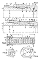
- FIG. 1 illustrates the front end of a large-caliber weapon barrel 12 which, for example, has a caliber diameter d2 of 155 mm and on the outside receives a muzzle brake 10.1 in a manner known per se.
- the muzzle brake 10.1 can be placed coaxially to the barrel core axis 16 at the muzzle end of the gun barrel 12 up to a radially extending annular stop 20 and contains an internal thread 42 which can be screwed onto a corresponding external thread of the gun barrel 12 for fastening the muzzle brake 10.1.
- a spring 44 engaging in a groove 46 of the weapon barrel 12 secures the muzzle brake 12.1 against rotation.
- the muzzle brake 10.1 is given a defined position by a lock nut 62.
- the lock nut 62 is connected behind the muzzle brake 10.1 via a thread to the weapon barrel 12 and, when countered, shifts the muzzle brake 10.1 in the front direction 53, whereby, however, the stop 20 of the muzzle brake 10.1 is released by a gap 66 from the end face 36 of the weapon barrel 12 .
- the seal 64 which consists, for example, of an elastomer, can be destroyed by hot powder gases and powder residues and, in addition, corrosion damage caused by water and moisture on the centering bore 19 of the muzzle brake and on the centering jacket 21 of the weapon barrel 12 and, if appropriate, can occur on the mounting thread 42.
- the lock nut 62 had to be additionally secured against twisting and the spring 44 against radial removal by means of a securing element 58 which can be screwed onto the muzzle brake 10.1 by means of screws 60.
- FIGS. 2 to 5 illustrate the design and attachment of the muzzle brake 10 according to the invention at the front end of the weapon barrel 12.
- the muzzle brake 10 is connected to the weapon barrel 12 at its rear end enveloping the weapon barrel 12 via a separate tensioning device 22 and can be preloaded in a defined manner.
- the tensioning device 22 exerts a high tensile force on the rear end of the muzzle brake 10, so that the stop surface 20 of the muzzle brake 10 is pressed tightly against the end face 38 of the weapon barrel muzzle end.
- the clamping device consists of a flange 28 connected to the weapon barrel 12, which contains axially extending bores 32 for receiving screws 30, while the muzzle brake 10 has threaded bores 34 on the end face in a cylindrical extension 50 for fastening the screws 30.
- the screws 30 of the clamping device 22 consist of a high-strength material, preferably steel, with a minimum tensile strength of 1200 N / mm2.
- the flange 28 is supported in a space-saving manner via a fine thread 36 with respect to the weapon barrel 12.
- the high-strength screws 30 can be heavily loaded despite their space-saving dimensioning and therefore have a self-locking effect due to their high pretensioning force, so that additional screw locking elements can be omitted.
- the high, in the rearward direction 52, tensile force of the screws 30 is transmitted from the stop surface 20 of the muzzle brake 10 to the front end surface 38 of the weapon barrel 12, whereby a specific surface pressure of, for example, 200 N / mm2 with good between the stop surface 20 and the end surface 38 Sealing effect, in particular also against a gas pressure of 800 bar existing during the shooting operation.
- the centering 19, 21 and the thread 42 are thereby protected against corrosion damage, the use of the known sealing ring 64 being unnecessary.
- the muzzle brake 10 can be secured against rotation by a spring 44 with the screw connection 48 as before.
- the tensioning device according to the invention enables the thread 42 and the spring 44 with the groove 46 to be eliminated even due to the high pretension.
- Figures 3 to 5 show the gas outlet openings 14 arranged in the lateral length region of the muzzle brake 10 transversely to the tube core axis 16, the rear gas outlet opening 14 having a minimum opening length l 1.
- the axial inner bore 18 of the muzzle brake 10 has a pull diameter d 1 and not the caliber diameter d 2 of the weapon barrel 12 corresponding inner diameter d, its rear end ending on the surface of the radially extending stop 20.
- the gas outlet openings 14 have baffle and sliding surfaces 24, 26 which have a different opening length 1 in the rear area of the muzzle brake 10 and an identical opening length 1 in the front area, each with a constant opening width b.
- the opening length l1 increases up to half the effective length l2 of the muzzle brake 10 and remains constant in the subsequent half of the length l2.
- the angles .alpha., .Beta. Of the baffle surface 24 and the sliding surface 26 are designed at different angles to the inner bore 18.
- the angle ⁇ of the baffle surface 24 ensures an optimal deflection of the outlet gases in an angular range of 100 to 105 ° to the inner bore 18 and, in cooperation with the gas outlet openings 14 corresponding to the maximum opening length l 1, a 50% reduction in return energy of the weapon barrel 12.
- the return energy can be reduced from 1200 kN to 600 kN.
- the angle ⁇ of the gas guide surface 26 ensures an interference-free gas discharge in an angular range from 110 to 120 ° to the inner bore 18.
- a particularly favorable braking effect of the weapon barrel 12 is achieved when the baffle surface 24 is arranged at an angle ⁇ of 102 ° and the gas guide surface 26 is arranged at an angle ⁇ of 114 ° with respect to the inner bore 18, the baffle surface 24 also having a diameter d3 outgoing approach 54 can be carried out enlarged.
- the muzzle brake 10 is further characterized by a short design, the effective length l2 of the muzzle brake 10 compared to the caliber diameter d2 of the barrel 12 only having a ratio between 4 and 5.
- the muzzle brake 10 is provided with a large number of gas outlet openings 14, for example with 14 gas outlet openings 14 arranged on both sides.
- the short design and a flattening 56 arranged above and below in the entire length range l 2 of the muzzle brake 10 have a weight-reducing and thus positive effect with regard to the prestressing forces to be applied by the tensioning device.
- the muzzle brake contains a drain opening 40, which is preferably arranged in the rear lower region of the muzzle brake 10.
Landscapes
- Engineering & Computer Science (AREA)
- General Engineering & Computer Science (AREA)
- Portable Nailing Machines And Staplers (AREA)
- Braking Arrangements (AREA)
Claims (10)
- Compensateur de recul pour tube d'arme (12), qui peut être monté coaxialement sur l'extrémité de l'embouchure du tube de l'arme jusqu'à une butée de forme annulaire et radiale, l'extrémité arrière de l'alésage interne (18) du compensateur de recul se terminant sur la surface de butée radiale et comprenant sur sa zone longitudinale latérale des ouvertures de sortie de gaz (14) disposées transversalement à l'axe (16) de l'âme du tube, qui présentent à l'extrémité arrière du compensateur de recul (10) une longueur d'ouverture minimale (l₁), caractérisé en ce que- l'alésage interne axial (18) du compensateur de recul (10) présente un diamètre interne (d) correspondant au diamètre au fond des rayures (d₁) du tube d'arme (12),- le compensateur de recul (10) peut être relié au tube d'arme (12) et soumis à une précontrainte définie à son extrémité arrière entourant le tube d'arme (12) par un dispositif de serrage séparé (22), le dispositif de serrage étant constitué par une bride (28) d'un seul tenant raccordée au tube d'arme (12), qui comprend des alésages (32) orientés axialement pour la réception de boulons (30) et le compensateur de recul (10) comprend sur son côté frontal des alésages à boulon (34) pour la fixation des boulons (30) qui exercent une force de traction élevée sur l'extrémité arrière du compensateur de recul (10), de manière que la surface de butée (20) s'applique de façon étanche en étant pressée contre le côté frontal (38) de l'extrémité de l'embouchure du tube de l'arme,- partant du diamètre au fond des rayures (d), les ouvertures de sortie de gaz (14) comprennent des surfaces de renvoi et directrices (24, 26), qui présentent dans la région arrière du compensateur de recul (10) une longueur d'ouverture (l₁) différente et dans la région avant une longueur d'ouverture qui reste égale et plus petite que le diamètre (d) au fond des rayure
- Compensateur de recul selon la revendication 1, caractérisé en ce que les boulons (30) du dispositif de serrage (22) sont constitués en un matériau présentant une résistance à la traction minimale de 1200 N/mm².
- Compensateur de recul selon la revendication 1, caractérisé en ce que la bride (12) est reliée au tube de l'arme par un filetage fin (36).
- Compensateur de recul selon la revendication 1, caractérisé en ce que la longueur d'ouverture (l₁) des ouvertures de sortie de gaz (14) augmente de façon constante jusqu'à la moitié de la longueur active (l₂) du compensateur de recul (10) et reste constante dans la moitié restante de la longueur (l₂).
- Compensateur de recul selon la revendication 1, caractérisé en ce que les angles (α, β) de la surface de renvoi (24) et de la surface directrice (26) présentent une inclinaison différente par rapport à l'alésage interne (18).
- Compensateur de recul selon la revendication 5, caractérisé en ce que l'angle (α) de la surface de renvoi (24) est compris dans une plage angulaire de 100 à 105° par rapport à l'alésage interne (18) et l'angle (β) de la surface directrice (26) dans une plage angulaire de 110 à 120° par rapport à l'alésage interne (18).
- Compensateur de recul selon les revendications 5 et 6, caractérisé en ce que la surface de renvoi (24) forme un angle de 102° avec l'alésage interne (18) et la surface directrice (26) un angle (β) de 114°.
- Compensateur de recul selon l'une quelconque des revendications 1 à 7, caractérisé en ce que la longueur active (l₂) du compensateur de recul (10) présente un rapport compris entre 4 et 5 avec le diamètre (d₂) du calibre du tube d'arme (12).
- Compensateur de recul selon l'une quelconque des revendications 1 à 8, caractérisé par un à-plat (56) prévu au-dessus et au-dessous sur la totalité de la région longitudinale (l₂) du compensateur de recul (10).
- Compensateur de recul selon l'une quelconque des revendications 1 à 9, caractérisé par une ouverture d'échappement (40) disposée de préférence dans la partie arrière inférieure du compensateur de recul (10).
Applications Claiming Priority (2)
| Application Number | Priority Date | Filing Date | Title |
|---|---|---|---|
| DE4025546A DE4025546C2 (de) | 1990-08-11 | 1990-08-11 | Mündungsbremse für eine großkalibrige Rohrwaffe |
| DE4025546 | 1990-08-11 |
Publications (2)
| Publication Number | Publication Date |
|---|---|
| EP0471920A1 EP0471920A1 (fr) | 1992-02-26 |
| EP0471920B1 true EP0471920B1 (fr) | 1995-02-22 |
Family
ID=6412105
Family Applications (1)
| Application Number | Title | Priority Date | Filing Date |
|---|---|---|---|
| EP91105675A Expired - Lifetime EP0471920B1 (fr) | 1990-08-11 | 1991-04-10 | Compensateur de recul pour canon à gros calibre |
Country Status (3)
| Country | Link |
|---|---|
| US (1) | US5119716A (fr) |
| EP (1) | EP0471920B1 (fr) |
| DE (2) | DE4025546C2 (fr) |
Families Citing this family (18)
| Publication number | Priority date | Publication date | Assignee | Title |
|---|---|---|---|---|
| US5279200A (en) * | 1992-07-13 | 1994-01-18 | Browning | Ballistic optimizing system for rifles |
| FR2729464A1 (fr) * | 1995-01-18 | 1996-07-19 | Giat Ind Sa | Frein de bouche pour canons de moyen ou de gros calibre |
| US5698810A (en) * | 1995-11-29 | 1997-12-16 | Browning Arms Company | Convertible ballistic optimizing system |
| US5798473A (en) * | 1997-04-30 | 1998-08-25 | Roblyer; Steven | Harmonic optimization system for rifles |
| WO1999051929A1 (fr) | 1998-04-02 | 1999-10-14 | Roblyer Steven P | Technique d'optimisation d'harmoniques |
| US6668699B2 (en) * | 1998-08-20 | 2003-12-30 | Ronnie David Russell | Porous nozzle projectile barrel |
| US6752062B2 (en) * | 2001-12-07 | 2004-06-22 | George M. Vais | Muzzle brake |
| US6782651B1 (en) * | 2003-02-12 | 2004-08-31 | Inpromarketing Corp. | Breaching tool |
| US7143680B2 (en) * | 2003-04-08 | 2006-12-05 | Bender Terrence D | Recoil and muzzle blast dissipator |
| US7581482B1 (en) * | 2005-07-28 | 2009-09-01 | The United States Of America As Represented By The Secretary Of The Army | Supersonic turning vane |
| DE102007024515A1 (de) | 2007-05-24 | 2008-11-27 | Rheinmetall Waffe Munition Gmbh | Vorrichtung und Verfahren zur Befestigung einer Mündungsbremse an einem Waffenrohr |
| US8025003B1 (en) * | 2009-10-14 | 2011-09-27 | The United States Of America As Represented By The Secretary Of The Navy | Fluted firearm barrel |
| DE102016000437A1 (de) * | 2016-01-18 | 2017-07-20 | Prime Manufacturing Group Limited (BVI) | Einrichtung zum lösbaren Befestigen eines Schalldämpfers und Schalldämpferanordnung |
| US10619964B2 (en) * | 2017-01-11 | 2020-04-14 | Palmetto State Armory, LLC | Modified pistol upper |
| US10337820B2 (en) * | 2017-11-21 | 2019-07-02 | John Jager | Firearm muzzle device clamp |
| USD868197S1 (en) | 2017-12-13 | 2019-11-26 | In Ovation, LLC | Firearm compensator |
| US12228360B2 (en) | 2021-09-01 | 2025-02-18 | In Ovation Llc | Firearm compensator |
| USD1022106S1 (en) | 2021-09-29 | 2024-04-09 | In Ovation Llc | Firearm compensator |
Family Cites Families (16)
| Publication number | Priority date | Publication date | Assignee | Title |
|---|---|---|---|---|
| DE169838C (fr) * | ||||
| US1363058A (en) * | 1921-02-10 | 1920-12-21 | T F Shanahn | Car construction |
| GB167728A (en) * | 1921-02-10 | 1921-08-18 | Schneider & Cie | Improvements in apparatus for reducing the length of recoil in guns |
| GB184911A (en) * | 1921-05-31 | 1922-08-31 | Harry Lawley Milner | Improvements in or relating to cocks and valves |
| US1605393A (en) * | 1925-07-20 | 1926-11-02 | Jr Richard M Cutts | Climb arrester |
| BE410174A (fr) * | 1934-07-16 | |||
| GB454533A (en) * | 1936-02-03 | 1936-10-02 | Vickers Armstrongs Ltd | Improvements in or relating to means for modifying the recoil of a gun |
| FR958162A (fr) * | 1947-05-31 | 1950-03-04 | ||
| US3141376A (en) * | 1955-06-13 | 1964-07-21 | George M Chinn | Flame-out eliminator |
| DE1553895A1 (de) * | 1967-04-01 | 1972-04-13 | Tampella Oy Ab | Rohrende bzw. Muendungsaufsatz an Rohren fuer drallose Geschosse |
| US3703122A (en) * | 1970-12-10 | 1972-11-21 | Gen Electric | Muzzle brake torque assist for multi-barrel weapons |
| US4207799A (en) * | 1977-02-14 | 1980-06-17 | Tocco Charles T | Muzzle brake |
| DE3203807A1 (de) * | 1982-02-04 | 1983-08-11 | Rheinmetall GmbH, 4000 Düsseldorf | Muendungsbremse |
| US4545285A (en) * | 1982-06-15 | 1985-10-08 | Mclain Clifford E | Matched expansion muzzle brake |
| US4811648A (en) * | 1987-09-14 | 1989-03-14 | Blackwell David L | Muzzle brake device |
| US4919035A (en) * | 1989-03-06 | 1990-04-24 | Pinkston Mark C | Muzzle brake and tool for installation |
-
1990
- 1990-08-11 DE DE4025546A patent/DE4025546C2/de not_active Expired - Fee Related
-
1991
- 1991-04-10 DE DE59104666T patent/DE59104666D1/de not_active Expired - Fee Related
- 1991-04-10 EP EP91105675A patent/EP0471920B1/fr not_active Expired - Lifetime
- 1991-06-28 US US07/723,062 patent/US5119716A/en not_active Expired - Lifetime
Also Published As
| Publication number | Publication date |
|---|---|
| EP0471920A1 (fr) | 1992-02-26 |
| DE59104666D1 (de) | 1995-03-30 |
| DE4025546A1 (de) | 1992-02-13 |
| US5119716A (en) | 1992-06-09 |
| DE4025546C2 (de) | 2002-03-14 |
Similar Documents
| Publication | Publication Date | Title |
|---|---|---|
| EP0471920B1 (fr) | Compensateur de recul pour canon à gros calibre | |
| EP1338859B1 (fr) | Canon d'une arme à feu avec frein de bouche | |
| EP2867607B1 (fr) | Silencieux pour une arme portative | |
| DE69604097T2 (de) | Mündungsbremse für ein mittel- oder grosskalibriges Geschütz | |
| DE60012269T2 (de) | Vorrichtung zur Befestigung einer Mündungsbremse an einem Waffenlauf | |
| EP0660915B1 (fr) | Silencieux pour armes a feu | |
| DE2057995A1 (de) | Handfeuerwaffe mit auswechselbarem Lauf | |
| DE202018005980U1 (de) | System zur schnellen Montage und Demontage eines Schalldämpfers auf dem Lauf einer Feuerwaffe | |
| EP0291845A1 (fr) | Projectile à noyau et à enveloppe | |
| DE19841585A1 (de) | Waffenrohr mit einer im Bereich der Rohrmündung angeordneten Kollimatorhalterung | |
| EP0221917B1 (fr) | Projectile sous-calibre | |
| DE3322979C2 (de) | Vorrichtung zur Fixierung und Einspannung eines Einsteckrohres in einem Waffenrohr | |
| DE19704489C2 (de) | Unterkalibriges Treibspiegelgeschoß | |
| DE602006000111T2 (de) | Führungsband für Artilleriegeschoss | |
| DE2232866B2 (de) | Lösbare Verbindung zwischen Geschoß und Treibladungshülse | |
| DE3046639A1 (de) | Einrichtung an einem waffenrohr zur verringerung des abgangsfehlerwinkels | |
| DE2227656A1 (de) | Unterkalibergeschoss | |
| EP0560078A2 (fr) | Dispositif fixé au canon d'une arme à feu et destiné à la réduction de l'influence des ondes de choc | |
| EP3926292B1 (fr) | Projectile et munition | |
| EP1312886B1 (fr) | Barillet de munitions pour arme à feu | |
| AT385595B (de) | Einrichtung zum verschiessen von unterkalibrigen geschossen | |
| DE2856859A1 (de) | Uebungsflugkoerper mit drallstabilisierung | |
| DE10254975B3 (de) | Hochlasttragende, dünnwandige, mehrteilige Rohrstruktur | |
| DE42924C (de) | Geschützrohr, welches aus normal zur Seelenachse stehenden Metallscheiben zusammengesetzt ist | |
| CH670882A5 (en) | Nose section of explosive shell - has core with three parts connected by tie bolt, with high compressive strength tungsten middle part |
Legal Events
| Date | Code | Title | Description |
|---|---|---|---|
| PUAI | Public reference made under article 153(3) epc to a published international application that has entered the european phase |
Free format text: ORIGINAL CODE: 0009012 |
|
| 17P | Request for examination filed |
Effective date: 19911211 |
|
| AK | Designated contracting states |
Kind code of ref document: A1 Designated state(s): DE FR GB IT NL |
|
| RAP3 | Party data changed (applicant data changed or rights of an application transferred) |
Owner name: RHEINMETALL GMBH |
|
| 17Q | First examination report despatched |
Effective date: 19931007 |
|
| ITF | It: translation for a ep patent filed | ||
| RAP1 | Party data changed (applicant data changed or rights of an application transferred) |
Owner name: RHEINMETALL INDUSTRIE GMBH |
|
| GRAA | (expected) grant |
Free format text: ORIGINAL CODE: 0009210 |
|
| AK | Designated contracting states |
Kind code of ref document: B1 Designated state(s): DE FR GB IT NL |
|
| GBT | Gb: translation of ep patent filed (gb section 77(6)(a)/1977) |
Effective date: 19950224 |
|
| REF | Corresponds to: |
Ref document number: 59104666 Country of ref document: DE Date of ref document: 19950330 |
|
| ET | Fr: translation filed | ||
| PLBE | No opposition filed within time limit |
Free format text: ORIGINAL CODE: 0009261 |
|
| STAA | Information on the status of an ep patent application or granted ep patent |
Free format text: STATUS: NO OPPOSITION FILED WITHIN TIME LIMIT |
|
| 26N | No opposition filed | ||
| PGFP | Annual fee paid to national office [announced via postgrant information from national office to epo] |
Ref country code: NL Payment date: 19970331 Year of fee payment: 7 |
|
| PG25 | Lapsed in a contracting state [announced via postgrant information from national office to epo] |
Ref country code: NL Free format text: LAPSE BECAUSE OF NON-PAYMENT OF DUE FEES Effective date: 19981101 |
|
| NLV4 | Nl: lapsed or anulled due to non-payment of the annual fee |
Effective date: 19981101 |
|
| REG | Reference to a national code |
Ref country code: GB Ref legal event code: IF02 |
|
| PGFP | Annual fee paid to national office [announced via postgrant information from national office to epo] |
Ref country code: DE Payment date: 20030331 Year of fee payment: 13 |
|
| PGFP | Annual fee paid to national office [announced via postgrant information from national office to epo] |
Ref country code: GB Payment date: 20040331 Year of fee payment: 14 |
|
| PGFP | Annual fee paid to national office [announced via postgrant information from national office to epo] |
Ref country code: FR Payment date: 20040415 Year of fee payment: 14 |
|
| PG25 | Lapsed in a contracting state [announced via postgrant information from national office to epo] |
Ref country code: DE Free format text: LAPSE BECAUSE OF NON-PAYMENT OF DUE FEES Effective date: 20041103 |
|
| PG25 | Lapsed in a contracting state [announced via postgrant information from national office to epo] |
Ref country code: IT Free format text: LAPSE BECAUSE OF NON-PAYMENT OF DUE FEES Effective date: 20050410 Ref country code: GB Free format text: LAPSE BECAUSE OF NON-PAYMENT OF DUE FEES Effective date: 20050410 |
|
| GBPC | Gb: european patent ceased through non-payment of renewal fee |
Effective date: 20050410 |
|
| PG25 | Lapsed in a contracting state [announced via postgrant information from national office to epo] |
Ref country code: FR Free format text: LAPSE BECAUSE OF NON-PAYMENT OF DUE FEES Effective date: 20051230 |
|
| REG | Reference to a national code |
Ref country code: FR Ref legal event code: ST Effective date: 20051230 |