EP0471990A2 - Haut-parleur à double bobine - Google Patents
Haut-parleur à double bobine Download PDFInfo
- Publication number
- EP0471990A2 EP0471990A2 EP91112202A EP91112202A EP0471990A2 EP 0471990 A2 EP0471990 A2 EP 0471990A2 EP 91112202 A EP91112202 A EP 91112202A EP 91112202 A EP91112202 A EP 91112202A EP 0471990 A2 EP0471990 A2 EP 0471990A2
- Authority
- EP
- European Patent Office
- Prior art keywords
- winding
- pole plate
- voice coil
- membrane
- basket
- Prior art date
- Legal status (The legal status is an assumption and is not a legal conclusion. Google has not performed a legal analysis and makes no representation as to the accuracy of the status listed.)
- Granted
Links
Images
Classifications
-
- H—ELECTRICITY
- H04—ELECTRIC COMMUNICATION TECHNIQUE
- H04R—LOUDSPEAKERS, MICROPHONES, GRAMOPHONE PICK-UPS OR LIKE ACOUSTIC ELECTROMECHANICAL TRANSDUCERS; ELECTRIC HEARING AIDS; PUBLIC ADDRESS SYSTEMS
- H04R9/00—Transducers of moving-coil, moving-strip, or moving-wire type
- H04R9/02—Details
- H04R9/04—Construction, mounting, or centering of coil
- H04R9/041—Centering
-
- H—ELECTRICITY
- H04—ELECTRIC COMMUNICATION TECHNIQUE
- H04R—LOUDSPEAKERS, MICROPHONES, GRAMOPHONE PICK-UPS OR LIKE ACOUSTIC ELECTROMECHANICAL TRANSDUCERS; ELECTRIC HEARING AIDS; PUBLIC ADDRESS SYSTEMS
- H04R1/00—Details of transducers, loudspeakers or microphones
- H04R1/20—Arrangements for obtaining desired frequency or directional characteristics
- H04R1/22—Arrangements for obtaining desired frequency or directional characteristics for obtaining desired frequency characteristic only
- H04R1/24—Structural combinations of separate transducers or of two parts of the same transducer and responsive respectively to two or more frequency ranges
Definitions
- the invention relates to a double coil loudspeaker, in which each of the two voice coils is acted upon by audio signals from different signal sources.
- loudspeakers which differ from conventionally known dynamic cone loudspeakers, for example illustrated in Funkschau 1983, No. 7, page 99, FIG. 1, only by a modified voice coil design, which is explained in more detail below, are used above all where there is space constraint To transmit sound signals from two different signal sources using only one membrane.
- this double-coil loudspeaker has two coil-shaped winding assemblies on the voice coil support, with one turn of the other winding assembly being arranged next to each turn of the first winding assembly. If the winding formations are laid around the voice coil carrier in multiple layers, this does not change the arrangement of the turns of the two winding formations described above in relation to one another in the respective positions. Only the individual windings of a lower layer are covered by windings in the layer above, which each belong to a different winding structure. The turns of all winding formations usually have the same wire cross-section.
- the effective conductor length of the two winding assemblies is adapted to the thickness of the pole plate adjacent to the winding assemblies or the thickness of this pole plate is adapted to the effective conductor lengths for the frequency spectra to be transmitted.
- the effective conductor length is understood to mean the longitudinal extent of the winding formations on the voice coil former parallel to the central axis of the loudspeaker. According to this explanation, it is also understandable in itself why the sound reproduction quality is reduced compared to single-coil loudspeakers when the two winding groups are subjected to sound signals of different frequency spectra.
- the well-known winding design with adjacent Windings of different winding connections have the effect that only one winding group can be optimally designed with regard to the effective conductor length for the frequency spectrum to be transmitted. But the winding bandage, whose effective conductor length is optimized, is still no guarantee of good sound reproduction behavior. This is because, due to the known arrangement of the winding associations on the voice coil former, the non-optimized winding association counteracts the optimized winding association with an increased ballast weight compared to a single-coil loudspeaker.
- the invention is therefore based on the object of specifying a double-coil loudspeaker whose sound reproduction quality is improved when sound signals of different frequency spectra are applied to the two winding groups.
- first winding assembly is arranged in one or more layers one above the other on the outer surface of the voice coil former, that around the first winding assembly on part of its surface, preferably in the area which is adjacent to the first pole plate when the system is at rest , the second wrap is placed and that the longitudinal and transverse dimensions of the second wrap are reduced compared to the longitudinal and transverse dimensions of the first wrap.
- the effective conductor lengths of the two winding groups can be adapted to the frequency spectra to be transmitted as well as the Select the impedances of the two coils independently of one another.
- an advantageous embodiment of the invention is specified in claim 2. If the first winding bandage is then designed for the reproduction of the low or broadband sound spectrum and the second winding bandage is designed exclusively for speech reproduction, this has the advantage that the second winding bandage can be kept very narrow because of the low amplitude during speech reproduction. Since the second winding bandage also allows the use of very thin wire cross sections due to its narrow design, the effective conductor length for this winding area can also be regarded as optimized. Due to the reduced geometric dimensions of the second winding area intended for speech reproduction and its reduced weight as a result, the sound reproduction in the low-range or broadband range which is effected by means of the first winding area is not influenced. In particular, the sound reproduction quality in the low and broadband range is comparable to the reproduction quality of a single-coil loudspeaker, while the sound quality in speech reproduction achieves an optimum that can be achieved with a double-coil loudspeaker.
- the double-coil loudspeaker specified in claim 2 in motor vehicles which have a car telephone system with hands-free function, since the double-coil loudspeaker according to the invention with its first winding assembly as a loudspeaker for the audio system of the motor vehicle and with its second winding assembly as a loudspeaker for the speech reproduction of the Handsfree phone can be used.
- the double-coil loudspeaker according to the invention with its first winding assembly as a loudspeaker for the audio system of the motor vehicle and with its second winding assembly as a loudspeaker for the speech reproduction of the Handsfree phone can be used.
- there is also no switchover unit which is necessary if how traditionally the cone speakers of the audio system simultaneously take over the sound reproduction of the telephone.
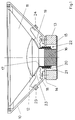
- the conventionally designed double-coil loudspeaker illustrated in FIG. 1 has a conical basket 10 in which the cone-shaped membrane 11 is inserted.
- the membrane 11 and the basket 10 are connected to one another at their ends, each of which has the larger diameter.
- the end of the membrane 11, which has the smaller diameter, is covered by a hemispherical dust cap 12 pointing towards the other end of the membrane 11.
- annular permanent magnet 13 is attached centrally to the central axis of the loudspeaker, with another between the end of the basket 10 and the permanent magnet 13 is also annular, but has a smaller inner diameter than the permanent magnet 13 pole plate 14 is interposed.
- the other annular surface of the permanent magnet 13 facing away from the basket 10 is covered with a disk-shaped second pole plate 15.
- a tubular voice coil former 17 is attached to the end of the membrane 11, which has the smaller diameter.
- a concertina-shaped centering membrane 18 is arranged between the inner surface of the basket 10 and the end of the voice coil bobbin 17, which faces the membrane 11. This ensures during operation of the loudspeaker that the voice coil bobbin 17 is always centered on the central axis of the loudspeaker.
- each turn 22 of a first winding assembly 20 is a turn 22 in the vertical extent subordinate to the other winding association 21.
- This arrangement of the turns 22 with respect to one another also applies in a horizontal extension if, as shown in FIG. 1, the winding assemblies 20, 21 are laid in multiple layers around the voice coil former 17.
- the cross section of the winding wire is the same for both winding groups 20, 21.
- the longitudinal extent of the winding formations 20, 21 on the voice coil bobbin 17 is selected so that the idle state of the loudspeaker means that the winding formations 20, 21 are approximately in the middle of the first pole plate 14 located next to it on the inside.
- the ends 23 of the winding wire of each winding assembly 20, 21 are guided to the connecting terminals 24, 25 arranged on the basket 10.
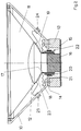
- FIG. 2 A double coil loudspeaker designed according to the invention is illustrated in FIG. 2. This differs from the double coil loudspeaker described in FIG. 1 by a different arrangement of the winding formations 20, 21 on the voice coil former 17.
- a first winding assembly 20 is placed in multiple layers around the outer jacket 19 of the voice coil bobbin 17.
- the second winding bandage 21 is also placed in multiple layers on this winding bandage 20.
- this winding assembly 21 is distinguished by a reduced wire cross section and a reduced winding width in the longitudinal direction of the voice coil bobbin 17.
- the longitudinal dimensions of both winding assemblies 20, 21 also protrude here, the first pole plate 14 arranged next to them at the same distance.
- each winding assembly 20, 21 can be adapted to the frequency spectrum to be transmitted in each case. If the second winding bandage 21 is designed for the voice reproduction of a telephone, this winding bandage 21, because of its light weight, has no influence on the reproduction quality of the other winding bandage 20 designed for a different frequency spectrum.
Landscapes
- Physics & Mathematics (AREA)
- Engineering & Computer Science (AREA)
- Acoustics & Sound (AREA)
- Signal Processing (AREA)
- Health & Medical Sciences (AREA)
- Otolaryngology (AREA)
- Audible-Bandwidth Dynamoelectric Transducers Other Than Pickups (AREA)
- Circuit For Audible Band Transducer (AREA)
Applications Claiming Priority (2)
| Application Number | Priority Date | Filing Date | Title |
|---|---|---|---|
| DE4025591A DE4025591A1 (de) | 1990-08-13 | 1990-08-13 | Doppelspulenlautsprecher |
| DE4025591 | 1990-08-13 |
Publications (3)
| Publication Number | Publication Date |
|---|---|
| EP0471990A2 true EP0471990A2 (fr) | 1992-02-26 |
| EP0471990A3 EP0471990A3 (en) | 1992-08-19 |
| EP0471990B1 EP0471990B1 (fr) | 1995-04-19 |
Family
ID=6412140
Family Applications (1)
| Application Number | Title | Priority Date | Filing Date |
|---|---|---|---|
| EP91112202A Expired - Lifetime EP0471990B1 (fr) | 1990-08-13 | 1991-07-20 | Haut-parleur à double bobine |
Country Status (3)
| Country | Link |
|---|---|
| EP (1) | EP0471990B1 (fr) |
| JP (1) | JPH04234300A (fr) |
| DE (2) | DE4025591A1 (fr) |
Cited By (2)
| Publication number | Priority date | Publication date | Assignee | Title |
|---|---|---|---|---|
| FR2807262A1 (fr) * | 2000-04-03 | 2001-10-05 | Sagem | Telephone mobile avec haut-parleur perfectionne |
| US9838794B2 (en) | 2013-04-26 | 2017-12-05 | Sound Solutions International Co., Ltd. | Double coil speaker |
Families Citing this family (2)
| Publication number | Priority date | Publication date | Assignee | Title |
|---|---|---|---|---|
| DE19953119C2 (de) * | 1999-11-04 | 2003-03-20 | Harman Audio Electronic Sys | Audioverstärker mit einer getakteten Endstufe |
| KR20060102199A (ko) * | 2005-03-23 | 2006-09-27 | 주식회사 청음전자 | 스피커 |
Family Cites Families (4)
| Publication number | Priority date | Publication date | Assignee | Title |
|---|---|---|---|---|
| NL6609729A (fr) * | 1965-07-16 | 1967-01-17 | ||
| US4088847A (en) * | 1975-12-11 | 1978-05-09 | Matsushita Electric Industrial Co., Ltd. | Speaker voice coil construction |
| DE3208409A1 (de) * | 1982-03-09 | 1983-09-15 | Hagenuk GmbH, 2300 Kiel | Dynamischer schallwandler |
| US4897877A (en) * | 1987-05-18 | 1990-01-30 | Oxford Speaker Company | Sub-woofer driver combination with dual voice coil arrangement |
-
1990
- 1990-08-13 DE DE4025591A patent/DE4025591A1/de not_active Withdrawn
-
1991
- 1991-07-20 DE DE59105234T patent/DE59105234D1/de not_active Expired - Fee Related
- 1991-07-20 EP EP91112202A patent/EP0471990B1/fr not_active Expired - Lifetime
- 1991-07-29 JP JP3210352A patent/JPH04234300A/ja active Pending
Cited By (3)
| Publication number | Priority date | Publication date | Assignee | Title |
|---|---|---|---|---|
| FR2807262A1 (fr) * | 2000-04-03 | 2001-10-05 | Sagem | Telephone mobile avec haut-parleur perfectionne |
| EP1146771A1 (fr) * | 2000-04-03 | 2001-10-17 | Sagem Sa | Téléphone mobile avec haut-parleur perfectionné |
| US9838794B2 (en) | 2013-04-26 | 2017-12-05 | Sound Solutions International Co., Ltd. | Double coil speaker |
Also Published As
| Publication number | Publication date |
|---|---|
| EP0471990B1 (fr) | 1995-04-19 |
| EP0471990A3 (en) | 1992-08-19 |
| JPH04234300A (ja) | 1992-08-21 |
| DE4025591A1 (de) | 1992-02-20 |
| DE59105234D1 (de) | 1995-05-24 |
Similar Documents
| Publication | Publication Date | Title |
|---|---|---|
| DE102014103324B4 (de) | Induktives Bauelement und Verfahren zum Herstellen eines induktiven Bauelements | |
| DE19654156C2 (de) | Lautsprechereinheit und die Lautsprechereinheit verwendendes Lautsprechersystem | |
| DE4317775A1 (de) | Lautsprecher | |
| EP0804048B1 (fr) | Haut-parleur | |
| DE2533163B2 (de) | Elektrischer Aufnehmer für ein Saiteninstrument, wie beispielsweise eine Gitarre | |
| AT143569B (de) | Akustischer Apparat. | |
| DE69112473T2 (de) | Lautsprecheranordnung und TV mit solcher Anordnung. | |
| DE10322692A1 (de) | Elektroakustischer Wandler | |
| EP0471990B1 (fr) | Haut-parleur à double bobine | |
| WO2001026412A2 (fr) | Haut-parleur multiple | |
| DE2161620B2 (de) | Richtungsabhaengiger breitbanduebertrager in gabelschaltung | |
| DE2362001A1 (de) | Dynamischer lautsprecher mit schwingspule | |
| DE2602668C3 (de) | Hochspannungsfester breitbandiger Übertrager für die Nachrichtentechnik | |
| DE102019120137B3 (de) | Elektrodynamischer Lautsprecher | |
| EP0582120A1 (fr) | Dispositif des haut-parleurs coaxials | |
| DE2637604B2 (de) | Verteilte Verzögerungsleitung | |
| DE3831376A1 (de) | Lautsprecher oder mikrofon | |
| DE4225854A1 (de) | Mittel-/Tiefton-Lautsprecher | |
| DE19637847A1 (de) | Elektro - akustische Wandler | |
| DE3223817C2 (fr) | ||
| DE1928118A1 (de) | Vorrichtung zur Ton-Wiedergabe | |
| DE3918654C2 (fr) | ||
| DE202019106955U1 (de) | Kalottenmembran, ausgeglichene Kalottenmembran und Lautsprecher | |
| DE502180C (de) | Verfahren zur drahtlosen Fernuebertragung von niederfrequenten Wellen (von Hoerfrequenz oder Bildfrequenz) mit Hilfe hochfrequenter Traegerwellen | |
| DE3633156A1 (de) | Schaltungsanordnung zur klangverbesserung von lautsprechern |
Legal Events
| Date | Code | Title | Description |
|---|---|---|---|
| PUAI | Public reference made under article 153(3) epc to a published international application that has entered the european phase |
Free format text: ORIGINAL CODE: 0009012 |
|
| AK | Designated contracting states |
Kind code of ref document: A2 Designated state(s): BE DE FR GB IT SE |
|
| RAP1 | Party data changed (applicant data changed or rights of an application transferred) |
Owner name: NOKIA (DEUTSCHLAND) GMBH |
|
| PUAL | Search report despatched |
Free format text: ORIGINAL CODE: 0009013 |
|
| AK | Designated contracting states |
Kind code of ref document: A3 Designated state(s): BE DE FR GB IT SE |
|
| 17P | Request for examination filed |
Effective date: 19921110 |
|
| 17Q | First examination report despatched |
Effective date: 19940322 |
|
| GRAA | (expected) grant |
Free format text: ORIGINAL CODE: 0009210 |
|
| AK | Designated contracting states |
Kind code of ref document: B1 Designated state(s): BE DE FR GB IT SE |
|
| ITF | It: translation for a ep patent filed | ||
| REF | Corresponds to: |
Ref document number: 59105234 Country of ref document: DE Date of ref document: 19950524 |
|
| GBT | Gb: translation of ep patent filed (gb section 77(6)(a)/1977) |
Effective date: 19950515 |
|
| ET | Fr: translation filed | ||
| PGFP | Annual fee paid to national office [announced via postgrant information from national office to epo] |
Ref country code: DE Payment date: 19950912 Year of fee payment: 5 |
|
| PLBE | No opposition filed within time limit |
Free format text: ORIGINAL CODE: 0009261 |
|
| STAA | Information on the status of an ep patent application or granted ep patent |
Free format text: STATUS: NO OPPOSITION FILED WITHIN TIME LIMIT |
|
| 26N | No opposition filed | ||
| PGFP | Annual fee paid to national office [announced via postgrant information from national office to epo] |
Ref country code: FR Payment date: 19960709 Year of fee payment: 6 |
|
| PGFP | Annual fee paid to national office [announced via postgrant information from national office to epo] |
Ref country code: GB Payment date: 19960711 Year of fee payment: 6 |
|
| PGFP | Annual fee paid to national office [announced via postgrant information from national office to epo] |
Ref country code: SE Payment date: 19960717 Year of fee payment: 6 |
|
| PGFP | Annual fee paid to national office [announced via postgrant information from national office to epo] |
Ref country code: BE Payment date: 19960911 Year of fee payment: 6 |
|
| PG25 | Lapsed in a contracting state [announced via postgrant information from national office to epo] |
Ref country code: DE Effective date: 19970402 |
|
| PG25 | Lapsed in a contracting state [announced via postgrant information from national office to epo] |
Ref country code: GB Free format text: LAPSE BECAUSE OF NON-PAYMENT OF DUE FEES Effective date: 19970720 |
|
| PG25 | Lapsed in a contracting state [announced via postgrant information from national office to epo] |
Ref country code: SE Effective date: 19970721 |
|
| PG25 | Lapsed in a contracting state [announced via postgrant information from national office to epo] |
Ref country code: BE Free format text: LAPSE BECAUSE OF NON-PAYMENT OF DUE FEES Effective date: 19970731 |
|
| BERE | Be: lapsed |
Owner name: NOKIA (DEUTSCHLAND) G.M.B.H. Effective date: 19970731 |
|
| GBPC | Gb: european patent ceased through non-payment of renewal fee |
Effective date: 19970720 |
|
| PG25 | Lapsed in a contracting state [announced via postgrant information from national office to epo] |
Ref country code: FR Free format text: LAPSE BECAUSE OF NON-PAYMENT OF DUE FEES Effective date: 19980331 |
|
| EUG | Se: european patent has lapsed |
Ref document number: 91112202.6 |
|
| REG | Reference to a national code |
Ref country code: FR Ref legal event code: ST |
|
| PG25 | Lapsed in a contracting state [announced via postgrant information from national office to epo] |
Ref country code: IT Free format text: LAPSE BECAUSE OF NON-PAYMENT OF DUE FEES;WARNING: LAPSES OF ITALIAN PATENTS WITH EFFECTIVE DATE BEFORE 2007 MAY HAVE OCCURRED AT ANY TIME BEFORE 2007. THE CORRECT EFFECTIVE DATE MAY BE DIFFERENT FROM THE ONE RECORDED. Effective date: 20050720 |