EP0471994B1 - Ausfallsicherer elektrischer Steckverbinder - Google Patents
Ausfallsicherer elektrischer Steckverbinder Download PDFInfo
- Publication number
- EP0471994B1 EP0471994B1 EP91112350A EP91112350A EP0471994B1 EP 0471994 B1 EP0471994 B1 EP 0471994B1 EP 91112350 A EP91112350 A EP 91112350A EP 91112350 A EP91112350 A EP 91112350A EP 0471994 B1 EP0471994 B1 EP 0471994B1
- Authority
- EP
- European Patent Office
- Prior art keywords
- check signal
- socket
- plug portion
- plug
- check
- Prior art date
- Legal status (The legal status is an assumption and is not a legal conclusion. Google has not performed a legal analysis and makes no representation as to the accuracy of the status listed.)
- Expired - Lifetime
Links
Images



Classifications
-
- B—PERFORMING OPERATIONS; TRANSPORTING
- B60—VEHICLES IN GENERAL
- B60R—VEHICLES, VEHICLE FITTINGS, OR VEHICLE PARTS, NOT OTHERWISE PROVIDED FOR
- B60R21/00—Arrangements or fittings on vehicles for protecting or preventing injuries to occupants or pedestrians in case of accidents or other traffic risks
- B60R21/01—Electrical circuits for triggering passive safety arrangements, e.g. airbags, safety belt tighteners, in case of vehicle accidents or impending vehicle accidents
- B60R21/017—Electrical circuits for triggering passive safety arrangements, e.g. airbags, safety belt tighteners, in case of vehicle accidents or impending vehicle accidents including arrangements for providing electric power to safety arrangements or their actuating means, e.g. to pyrotechnic fuses or electro-mechanic valves
- B60R21/0173—Diagnostic or recording means therefor
-
- H—ELECTRICITY
- H01—ELECTRIC ELEMENTS
- H01R—ELECTRICALLY-CONDUCTIVE CONNECTIONS; STRUCTURAL ASSOCIATIONS OF A PLURALITY OF MUTUALLY-INSULATED ELECTRICAL CONNECTING ELEMENTS; COUPLING DEVICES; CURRENT COLLECTORS
- H01R13/00—Details of coupling devices of the kinds covered by groups H01R12/70 or H01R24/00 - H01R33/00
- H01R13/64—Means for preventing incorrect coupling
- H01R13/641—Means for preventing incorrect coupling by indicating incorrect coupling; by indicating correct or full engagement
-
- B—PERFORMING OPERATIONS; TRANSPORTING
- B60—VEHICLES IN GENERAL
- B60R—VEHICLES, VEHICLE FITTINGS, OR VEHICLE PARTS, NOT OTHERWISE PROVIDED FOR
- B60R21/00—Arrangements or fittings on vehicles for protecting or preventing injuries to occupants or pedestrians in case of accidents or other traffic risks
- B60R21/01—Electrical circuits for triggering passive safety arrangements, e.g. airbags, safety belt tighteners, in case of vehicle accidents or impending vehicle accidents
- B60R2021/01006—Mounting of electrical components in vehicles
Definitions
- the present invention relates to connectors for connecting, for example, the output of a controller of an air bag system to the control units of air bags for the driver and the front passenger.
- Fig. 1 shows an air bag system mounted in an automobile which includes an air bag 2 for the driver which is mounted on a steering wheel 1; an air bag 3 for the front passenger; a controller 4 having a sensor therein; and a connector 5 for connecting the output of the controller 4 to the control units of the air bags 2 and 3.
- the sensor senses the impact and sets the controller 4 in operation to control the control units of the air bags 2 and 3 so that the air bags 2 and 3 instantly expand to protect the driver and the passenger from the impact.
- the connector 5 includes a plug and a socket.
- the plug is connected to the socket to carry the main signal.
- the main signal is carried even if the plug is loosely connected to the socket. If an automobile is shipped with a loosely connected connector, the plug can get out of the socket with vibrations in use, and the air bags can fail to operate in the event of an accident.
- a connector structure comprising:
- the connector structure is characterized in that, the main signed socket has a lock mechanism adapted to be engaged with a lock portion of a lock mechanism insertion dent of the main signal plug portion when it completely fits, the fitting portion of the check signal plug portion has a protrusion formed thereon, and the check signal socket is adapted to make the protruded piece of the contact terminal of the check signal socket engage with the protrusion and the contact portion comes into contact with the contact terminal of the check signal plug portion when the check signal socket fits into the fitting portion of the check signal plug portion, and the protruded piece of the contact terminal of the check signal socket is blocked by the protrusion.
- the block device When the connection of the main signal socket to the main signal plug portion is completed, the block device permits the check signal socket to be fitted into the check signal plug portion so that the contact terminal of the check signal socket comes into contact with that of the check signal plug portion, indicating that the complete connection between the main signal socket and the main signal plug portion is established.
- the block device prevent the check signal socket from being inserted into the check signal plug portion, indicating that the connection is incomplete.
- the main signal socket is completely fitted into the main signal plug portion, it is impossible to fit the check signal socket into the check signal plug portion, thus providing automatic prevention of incomplete connections.
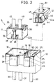
- the connector 5 includes a plug 10; a main signal socket 11; and a check signal socket 12.
- the plug 10 has a case 13 consisting of a two pole plug portion 14 for the main signals and a one pole plug portion 15 for the check signal.
- the main and check signal plug portions 14 and 15 have plug cavities 16 and 17, respectively, which is separated by a partition wall 18.
- the partition wall 18 has a pair of slits 19 extending downwardly from the top to the bottom thereof to form a tongue member 20.
- the tongue member 20 has a projection 21 extending into the plug cavity 16 from its top portion, forming a block arm 50.
- a pair of contact terminals 22 are mounted in the main signal plug portion 14 such that the contact portions 22a project into the plug cavity 16.
- a contact terminal 23 is mounted in the check signal plug portion 15 such that the contact portion 23a rests on a side wall 24 of the plug cavity 17.
- a pair of projected rims 25 are formed on opposite sides of the top portion of the contact portion 23a.
- a pair of lock receiving recesses 26 and 27 are formed on sides of the plug cavities 16 and 17 and have locking portions 28 and 29, respectively.
- a pair of main signal lines 30 and 31 and a check signal line 32 from the controller 4 are connected to the contact terminals 22 of the main signal plug portion 15 and the contact terminal 23 of the check signal plug portion 16, and the plug is incorporated in the air bag system.
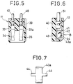
- the main signal socket 11 has a case 33 in which a pair of contact terminals 34 and 35 are mounted.
- a lock device 36 is provided on an outside of the case 33.
- the lock device 36 has a cantilever lock arm 37 extending upwardly from the front end of a side of the case 33.
- a pair of engaging projections 38 are provided on opposite sides of the lock arm 37.
- An engaging recess 39 is formed on the rear portion a side wall 33a of the case 33.
- a pair of signal lines 47 and 48 from the driver's and passenger's side air bags 2 and 3 are connected to the contact terminals 34 and 35, and the socket is incorporated in the air bag system.
- the check signal socket 12 has a case 40 having a terminal cavity 41 with an opening 42 on its side.
- a contact terminal 43 having a C-shaped cross section and a pair of lateral arms 44 is mounted in the terminal cavity 41 such that the contact portion 43a exposed through the opening 42.
- a lock device 45 is provided on an outside of the case 40.
- the lock device 45 has a cantilevered lock arm 46 extending rearwardly from the front end of a side of the case 40.
- a pair of engaging projections 49 are provided on opposite sides of the lock arm 46.
- a check signal line 51 is connected to the contact terminal 41, and the socket is incorporated in the air bag system.
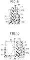
- the main signal socket 11 is fitted into the plug cavity 16 of the main signal plug portion 14 so that the contact terminals 34 are connected to the contact terminals 22. As shown by the broken line in Fig. 3, the front portion 33a of the main signal socket 11 contacts the projection 21 of the tongue member 20 to flex the tongue member 20 toward the plug cavity 17 of the check signal plug portion 15. When the contact terminal 34 is connected to the contact terminal 22 of the main signal plug portion 14, the projection 21 of the tongue member 29 snaps in the engaging recess 39 of the side wall 33a so that the block arm 50 returns to the original position as shown by the solid line in Fig. 3.
- the block arm 50 does not project into the plug cavity 17 of the check signal plug portion 15 so that it is possible to fit the check signal socket 12 into the plug cavity 17 of the check signal plug portion 12.
- the lateral arms 44 of the contact terminal 41 slide along the projected rims 25 of the check signal plug portion 15 so that the contact portion 43a of the contact terminal 43 flexes inwardly.
- the lateral arms 44 pass the projected rims 25 while the contact portion 43a of the contact terminal 43 comes into contact to the contact terminal 23 of the check signal plug portion 15.
- the cantilevered lock arm 46 of the check signal socket 12 is inserted into the lock device receiving recess 27 so that the engaging projections 49 engage the lock portion 29 of the receiving recess 27, thereby locking the check signal socket 12 to the check signal plug portion 15.
- connection of the main signal socket 11 to the main signal plug portion 14 is incomplete, the side wall 33a of the main signal socket 11 abuts on the projection 21 of the block arm 50 and flexes the block arm 50 toward the plug cavity 17 of the check signal plug portion 15 as shown by the broken line in Fig. 3 so that it is impossible to fit the check signal socket 12 into the plug cavity 17 of the check signal plug portion 15. Thus, it is indicated that the connection of the main signal socket 11 to the main signal plug portion 14 is incomplete.
Landscapes
- Engineering & Computer Science (AREA)
- Mechanical Engineering (AREA)
- Details Of Connecting Devices For Male And Female Coupling (AREA)
Claims (3)
- Steckeraufbau miteinem Steckerteil (10), einem Hauptsignalbuchsenteil (11) und einem Prüfsignalbuchsenteil (12), wobei der Steckerteil (10) mit einem Gehäusehauptkörper (13), der einen Hauptsignalsteckerteil (14) und einen Prüfsignalsteckerteil (15) aufweist, einer Blockeinrichtung (50), die zwischen Paßteilen des Hauptsignalsteckerteils (14) und des Prüfsignalsteckerteils (15) angeordnet sind, Kontaktanschlüssen (22, 23), die auf dem Hauptsignalstekkerteil (14) und dem Prüfsignalsteckerteil (15) angebracht sind, und Verriegelungsteilen (28, 29) versehen ist, die an den Paßteilen des Hauptsignalsteckerteils (14) und des Prüfsignalstekkerteils (15) ausgebildet sind, wobeider Hauptsignalbuchsenteil (11) einen Kontaktanschluß (34, 35) aufweist, der in Kontakt mit einem Kontaktanschluß (22) des Hauptsignalsteckerteils (14) des Steckerteils (10) kommt, wenn der Hauptsignalbuchsenteil (11) in den Paßteil des Hauptsignalsteckerteils (14) gepaßt wird, einen Stirnflächenteil, der mit dem Block (50) in Eingriff kommt, um den Block (50) in den Paßteil des Prüfsignalsteckerteils (15) zu versetzen, und einen Eingriffszahnteil (39) aufweist, der so am Stirnflächenteil ausgebildet ist, daß er mit dem Block (50) in Eingriff kommt, wenn dieser vollständig eingepaßt wird, undder Prüfsignalbuchsenteil (12) einen Kontaktanschluß (43), der mit einem Kontaktanschluß (23) des Prüfsignalsteckerteils (15) in Kontakt kommen kann, wenn der Prüfsignalbuchsenteil in den Paßteil des Prüfsignalsteckerteils (15) des Steckerteils (10) gepaßt wird, und einen Verriegelungsmechanismus (45) aufweist, der mit einem Verriegelungsteil (29) eines Einrastzahns (27) eines Verriegelungsmechanismus des Prüfsignalsteckerteils (15) in Eingriff kommen kann,dadurch gekennzeichnet, daß der Hauptsignalbuchsenteil (11) einen Verriegelungsmechnismus (36) aufweist, der mit einem Verriegelungsteil eines Einrastzahns (26) des Verriegelungsmechanismus des Hauptsignalsteckerteils (15) in Eingriff kommen kann, wenn dieser vollständig eingepaßt wird, der Paßteil des Prüfsignalsteckerteils (15) einen Vorsprung (25) aufweist, der daran ausgebildet ist, und der Prüfsignalbuchsenteil (12) so ausgebildet ist, daß er den vorstehenden Teil des Kontaktanschlusses (43) des Prüfsignalbuchsenteils (12) in Eingriff mit dem Vorsprung (25) bringt und den Kontaktteil in Kontakt mit dem Kontaktanschluß (23) des Prüfsignalsteckerteils (15) bringt, wenn der Prüfsignalbuchsenteil (12) in den Paßteil des Prüfsignalsteckerteils (15) gepaßt wird und der vorstehende Teil des Kontaktanschlusses (43) des Prüfsignalbuchsenteils (12) durch den Vorsprung (25) blockiert ist.
- Steckeraufbau nach Anspruch 1, bei dem ein Basisteil des Verriegelungsmechanismus (36) des Hauptsignalbuchsenteils (11) aus einem in Form eines vorstehenden Armes ausgebildeten Verriegelungsteil (37) besteht, der in einem Stück in einem Seitenbasisteil des Gehäusehauptkörpers (33) ausgebildet ist, und am Verriegelungsteil (37) ein Eingriffsvorsprung (38) ausgebildet ist.
- Steckeraufbau nach Anspruch 1, bei dem ein Basisteil des Verriegelungsmechanismus (45) des Prüfsignalbuchsenteils (12) aus einem in Form eines Armes ausgebildeten Verriegelungsteil (46) besteht, der in einem Stück an einem Seitenbasisteil eines Gehäusehauptkörpers (40) ausgebildet ist, und am Verriegelungsteil (46) ein Eingriffsvorsprung (49) ausgebildet ist.
Applications Claiming Priority (2)
| Application Number | Priority Date | Filing Date | Title |
|---|---|---|---|
| JP197725/90 | 1990-07-27 | ||
| JP2197725A JPH0485147A (ja) | 1990-07-27 | 1990-07-27 | コネクタ構造 |
Publications (2)
| Publication Number | Publication Date |
|---|---|
| EP0471994A1 EP0471994A1 (de) | 1992-02-26 |
| EP0471994B1 true EP0471994B1 (de) | 1996-01-03 |
Family
ID=16379309
Family Applications (1)
| Application Number | Title | Priority Date | Filing Date |
|---|---|---|---|
| EP91112350A Expired - Lifetime EP0471994B1 (de) | 1990-07-27 | 1991-07-23 | Ausfallsicherer elektrischer Steckverbinder |
Country Status (4)
| Country | Link |
|---|---|
| US (1) | US5151048A (de) |
| EP (1) | EP0471994B1 (de) |
| JP (1) | JPH0485147A (de) |
| DE (1) | DE69116031T2 (de) |
Families Citing this family (13)
| Publication number | Priority date | Publication date | Assignee | Title |
|---|---|---|---|---|
| FR2698731B1 (fr) * | 1992-12-02 | 1995-02-03 | Cinch Connecteurs Sa | Connecteur électrique. |
| US5336934A (en) * | 1992-12-17 | 1994-08-09 | Ford Motor Company | Electrical connection and interlock circuit system for vehicle electric drive |
| JPH06283233A (ja) * | 1993-03-27 | 1994-10-07 | Sumitomo Wiring Syst Ltd | 嵌合検知機能付きコネクタ |
| US5913703A (en) * | 1996-04-24 | 1999-06-22 | Sumitomo Wiring Systems, Ltd. | Connector assembly with sequentially engageable housings |
| ES1044626Y (es) * | 1999-11-26 | 2000-09-16 | Mecanismos Aux Ind | Conector elecrico perfeccionado. |
| US6257917B1 (en) | 2000-07-11 | 2001-07-10 | Itt Manufacturing Enterprises, Inc. | Connector latching arrangement |
| DE102009030092A1 (de) * | 2009-06-22 | 2010-12-30 | Rwe Ag | Ladekabelstecker für Elektrofahrzeuge |
| DE102009056517B4 (de) * | 2009-12-02 | 2011-07-28 | Tyco Electronics AMP GmbH, 64625 | Steckverbinderanordnung mit erstem und zweitem Stecker und Gegenstecker |
| JP5578927B2 (ja) | 2010-01-12 | 2014-08-27 | 矢崎総業株式会社 | 低挿入力コネクタ |
| KR101091660B1 (ko) | 2010-09-30 | 2011-12-08 | 현대자동차주식회사 | 차량용 콤비네이션 커넥터 |
| CN102468578B (zh) * | 2010-11-16 | 2016-03-16 | 泰科电子(上海)有限公司 | 电连接器的壳体的防误插接装置的设计方法 |
| US9142904B2 (en) * | 2014-01-14 | 2015-09-22 | Tyco Electronics Corporation | Electrical connector with terminal position assurance |
| EP3297100B1 (de) | 2016-08-25 | 2021-11-17 | ITT Manufacturing Enterprises LLC | Dichtungsverbindung mit niedrigem profil mit rastschnittstelle |
Family Cites Families (5)
| Publication number | Priority date | Publication date | Assignee | Title |
|---|---|---|---|---|
| US4542946A (en) * | 1983-03-11 | 1985-09-24 | Brand-Rex Company | Power safety lock system |
| US4927382A (en) * | 1987-11-03 | 1990-05-22 | Siemens Aktiengesellschaft | Electrical function group for a vehicle |
| JPH077682B2 (ja) * | 1988-01-28 | 1995-01-30 | マツダ株式会社 | 電気接続装置 |
| JPH0738311B2 (ja) * | 1988-04-06 | 1995-04-26 | アンプ インコーポレーテッド | 電気コネクタ |
| JP2561960B2 (ja) * | 1989-07-18 | 1996-12-11 | 矢崎総業株式会社 | 電気コネクタの嵌合確認装置 |
-
1990
- 1990-07-27 JP JP2197725A patent/JPH0485147A/ja active Pending
-
1991
- 1991-06-07 US US07/712,910 patent/US5151048A/en not_active Expired - Fee Related
- 1991-07-23 DE DE69116031T patent/DE69116031T2/de not_active Expired - Fee Related
- 1991-07-23 EP EP91112350A patent/EP0471994B1/de not_active Expired - Lifetime
Also Published As
| Publication number | Publication date |
|---|---|
| US5151048A (en) | 1992-09-29 |
| EP0471994A1 (de) | 1992-02-26 |
| DE69116031D1 (de) | 1996-02-15 |
| DE69116031T2 (de) | 1996-09-19 |
| JPH0485147A (ja) | 1992-03-18 |
Similar Documents
| Publication | Publication Date | Title |
|---|---|---|
| US5203718A (en) | Connector | |
| US5788522A (en) | Movable connector | |
| US5628649A (en) | Lock detecting structure of connector | |
| US5174787A (en) | Electrical connector with check terminal | |
| US5145356A (en) | Electrical connector housings | |
| EP0344691B1 (de) | Doppeleinfügungsstruktur für Anschlussklemmen in Steckverbindern | |
| JP3315313B2 (ja) | コネクタ構造 | |
| US5151048A (en) | Failsafe electrical connector | |
| US6027364A (en) | Connector fitting construction with side ribs and corresponding side rib-receiving portions | |
| US5015199A (en) | Electric connector | |
| US5924885A (en) | Axial connection with position assurance system | |
| JPH0770337B2 (ja) | コネクタの結合検知装置 | |
| EP0387683B1 (de) | Elektrischer Steckverbinder | |
| EP1054481B1 (de) | Ein Verbinder | |
| EP0624930B1 (de) | Verbinder mit selektiv aufhebbarem Kurzschluss der Anschlüsse | |
| US5088938A (en) | Terminal locking block for electrical connectors | |
| JPH01274368A (ja) | 電気コネクタ | |
| US5980297A (en) | Lock arm deformation prevention construction | |
| US6186805B1 (en) | Short circuit electrical connector | |
| JP3230996B2 (ja) | コネクタ | |
| US5564953A (en) | Divided-type multi-pole connector | |
| US5462449A (en) | Electrical connector with a function of detecting interfitting engagement of connector housings | |
| EP0828321A2 (de) | Verbinder für Airbagsystem | |
| US5588872A (en) | Connector with engagement checking structure | |
| EP0657968B1 (de) | Verbinder mit Verriegelungserkennung |
Legal Events
| Date | Code | Title | Description |
|---|---|---|---|
| PUAI | Public reference made under article 153(3) epc to a published international application that has entered the european phase |
Free format text: ORIGINAL CODE: 0009012 |
|
| AK | Designated contracting states |
Kind code of ref document: A1 Designated state(s): DE FR GB IT |
|
| 17P | Request for examination filed |
Effective date: 19920429 |
|
| 17Q | First examination report despatched |
Effective date: 19940706 |
|
| GRAA | (expected) grant |
Free format text: ORIGINAL CODE: 0009210 |
|
| AK | Designated contracting states |
Kind code of ref document: B1 Designated state(s): DE FR GB IT |
|
| ITF | It: translation for a ep patent filed | ||
| REF | Corresponds to: |
Ref document number: 69116031 Country of ref document: DE Date of ref document: 19960215 |
|
| ET | Fr: translation filed | ||
| PLBE | No opposition filed within time limit |
Free format text: ORIGINAL CODE: 0009261 |
|
| STAA | Information on the status of an ep patent application or granted ep patent |
Free format text: STATUS: NO OPPOSITION FILED WITHIN TIME LIMIT |
|
| 26N | No opposition filed | ||
| PGFP | Annual fee paid to national office [announced via postgrant information from national office to epo] |
Ref country code: GB Payment date: 19980630 Year of fee payment: 8 |
|
| PGFP | Annual fee paid to national office [announced via postgrant information from national office to epo] |
Ref country code: FR Payment date: 19980731 Year of fee payment: 8 Ref country code: DE Payment date: 19980731 Year of fee payment: 8 |
|
| PG25 | Lapsed in a contracting state [announced via postgrant information from national office to epo] |
Ref country code: GB Free format text: LAPSE BECAUSE OF NON-PAYMENT OF DUE FEES Effective date: 19990723 |
|
| PG25 | Lapsed in a contracting state [announced via postgrant information from national office to epo] |
Ref country code: FR Free format text: THE PATENT HAS BEEN ANNULLED BY A DECISION OF A NATIONAL AUTHORITY Effective date: 19990731 |
|
| GBPC | Gb: european patent ceased through non-payment of renewal fee |
Effective date: 19990723 |
|
| PG25 | Lapsed in a contracting state [announced via postgrant information from national office to epo] |
Ref country code: DE Free format text: LAPSE BECAUSE OF NON-PAYMENT OF DUE FEES Effective date: 20000503 |
|
| REG | Reference to a national code |
Ref country code: FR Ref legal event code: ST |
|
| PG25 | Lapsed in a contracting state [announced via postgrant information from national office to epo] |
Ref country code: IT Free format text: LAPSE BECAUSE OF NON-PAYMENT OF DUE FEES;WARNING: LAPSES OF ITALIAN PATENTS WITH EFFECTIVE DATE BEFORE 2007 MAY HAVE OCCURRED AT ANY TIME BEFORE 2007. THE CORRECT EFFECTIVE DATE MAY BE DIFFERENT FROM THE ONE RECORDED. Effective date: 20050723 |