EP0472022A1 - Steckverbindung - Google Patents
Steckverbindung Download PDFInfo
- Publication number
- EP0472022A1 EP0472022A1 EP91112932A EP91112932A EP0472022A1 EP 0472022 A1 EP0472022 A1 EP 0472022A1 EP 91112932 A EP91112932 A EP 91112932A EP 91112932 A EP91112932 A EP 91112932A EP 0472022 A1 EP0472022 A1 EP 0472022A1
- Authority
- EP
- European Patent Office
- Prior art keywords
- cutting ring
- plug
- recess
- cutting
- connection according
- Prior art date
- Legal status (The legal status is an assumption and is not a legal conclusion. Google has not performed a legal analysis and makes no representation as to the accuracy of the status listed.)
- Granted
Links
- 238000005520 cutting process Methods 0.000 claims abstract description 51
- 229920001971 elastomer Polymers 0.000 claims abstract description 10
- 239000000806 elastomer Substances 0.000 claims abstract description 9
- RYGMFSIKBFXOCR-UHFFFAOYSA-N Copper Chemical compound [Cu] RYGMFSIKBFXOCR-UHFFFAOYSA-N 0.000 claims description 11
- 229910052802 copper Inorganic materials 0.000 claims description 11
- 239000010949 copper Substances 0.000 claims description 11
- XLYOFNOQVPJJNP-UHFFFAOYSA-N water Substances O XLYOFNOQVPJJNP-UHFFFAOYSA-N 0.000 claims description 7
- 238000007789 sealing Methods 0.000 claims description 6
- 210000000078 claw Anatomy 0.000 claims description 2
- 238000003780 insertion Methods 0.000 claims description 2
- 230000037431 insertion Effects 0.000 claims description 2
- 230000013011 mating Effects 0.000 claims 1
- 239000002184 metal Substances 0.000 claims 1
- 229910052751 metal Inorganic materials 0.000 claims 1
- 239000012858 resilient material Substances 0.000 claims 1
- 230000004888 barrier function Effects 0.000 abstract 1
- 238000004519 manufacturing process Methods 0.000 description 3
- 239000012530 fluid Substances 0.000 description 2
- 239000011324 bead Substances 0.000 description 1
- 230000008014 freezing Effects 0.000 description 1
- 238000007710 freezing Methods 0.000 description 1
- 238000004806 packaging method and process Methods 0.000 description 1
- 238000003825 pressing Methods 0.000 description 1
- 229910001220 stainless steel Inorganic materials 0.000 description 1
- 239000010935 stainless steel Substances 0.000 description 1
- 238000003860 storage Methods 0.000 description 1
Images

Classifications
-
- F—MECHANICAL ENGINEERING; LIGHTING; HEATING; WEAPONS; BLASTING
- F16—ENGINEERING ELEMENTS AND UNITS; GENERAL MEASURES FOR PRODUCING AND MAINTAINING EFFECTIVE FUNCTIONING OF MACHINES OR INSTALLATIONS; THERMAL INSULATION IN GENERAL
- F16L—PIPES; JOINTS OR FITTINGS FOR PIPES; SUPPORTS FOR PIPES, CABLES OR PROTECTIVE TUBING; MEANS FOR THERMAL INSULATION IN GENERAL
- F16L37/00—Couplings of the quick-acting type
- F16L37/08—Couplings of the quick-acting type in which the connection between abutting or axially overlapping ends is maintained by locking members
- F16L37/084—Couplings of the quick-acting type in which the connection between abutting or axially overlapping ends is maintained by locking members combined with automatic locking
-
- E—FIXED CONSTRUCTIONS
- E03—WATER SUPPLY; SEWERAGE
- E03C—DOMESTIC PLUMBING INSTALLATIONS FOR FRESH WATER OR WASTE WATER; SINKS
- E03C1/00—Domestic plumbing installations for fresh water or waste water; Sinks
- E03C1/02—Plumbing installations for fresh water
- E03C1/04—Water-basin installations specially adapted to wash-basins or baths
- E03C1/0403—Connecting the supply lines to the tap body
-
- F—MECHANICAL ENGINEERING; LIGHTING; HEATING; WEAPONS; BLASTING
- F16—ENGINEERING ELEMENTS AND UNITS; GENERAL MEASURES FOR PRODUCING AND MAINTAINING EFFECTIVE FUNCTIONING OF MACHINES OR INSTALLATIONS; THERMAL INSULATION IN GENERAL
- F16L—PIPES; JOINTS OR FITTINGS FOR PIPES; SUPPORTS FOR PIPES, CABLES OR PROTECTIVE TUBING; MEANS FOR THERMAL INSULATION IN GENERAL
- F16L37/00—Couplings of the quick-acting type
- F16L37/08—Couplings of the quick-acting type in which the connection between abutting or axially overlapping ends is maintained by locking members
- F16L37/084—Couplings of the quick-acting type in which the connection between abutting or axially overlapping ends is maintained by locking members combined with automatic locking
- F16L37/0842—Couplings of the quick-acting type in which the connection between abutting or axially overlapping ends is maintained by locking members combined with automatic locking by means of a ring which is split into a plurality of component parts which are held in place by means of a resilient ring member
-
- Y—GENERAL TAGGING OF NEW TECHNOLOGICAL DEVELOPMENTS; GENERAL TAGGING OF CROSS-SECTIONAL TECHNOLOGIES SPANNING OVER SEVERAL SECTIONS OF THE IPC; TECHNICAL SUBJECTS COVERED BY FORMER USPC CROSS-REFERENCE ART COLLECTIONS [XRACs] AND DIGESTS
- Y10—TECHNICAL SUBJECTS COVERED BY FORMER USPC
- Y10T—TECHNICAL SUBJECTS COVERED BY FORMER US CLASSIFICATION
- Y10T403/00—Joints and connections
- Y10T403/32—Articulated members
- Y10T403/32254—Lockable at fixed position
- Y10T403/32426—Plural distinct positions
- Y10T403/32434—Unidirectional movement, e.g., ratchet, etc.
Definitions
- the invention relates to a connection of a round rod, tube or the like. with a housing, in particular sanitary fitting, at least one elastomer seal and a cutting ring being provided for securing in the connection position.
- a connection is known from DE-OS 16 50 012.
- a special union nut screw connection is required, so that this type of connection is to be regarded as relatively complex.
- the union nut requires a relatively large amount of space, which is often not available in connection connections to the housing, in particular in sanitary fittings with a base mounting. It is therefore already known from DE 38 11 357 AI to use the connecting pipes in the battery body with a press fit after the fitting has been completed. However, it is necessary to adhere to tight tolerances in the connection area of the pipes and the bores in the housing.
- a relatively complex device for freezing the pipe pieces to be used is required.
- the invention is based on the object to provide a simple and inexpensive to manufacture, little space-consuming plug connection, which ensures a substantially non-detachable connection after assembly.
- the round rod or the tube is provided with a plug-in part which can be inserted into a bore in the housing, wherein a retraction lock in the form of a cutting ring is arranged in an annular recess, which with the reverse axial movement of the plug-in part one or more cutting edges clawed in the wall of the bore, so that a locking takes place in the plug-in position.
- the plug connection can be assembled at any time without special tools and devices, whereupon an inseparable connection is created between the housing and the round rod or tube. No larger space is required for the connection than for the plug-in part to be inserted itself.
- the plug-in connection according to the invention in particular the manufacture and assembly of sanitary single-hole mixer taps can be simplified. These fittings are generally designed so that they have two copper pipes with a diameter of about 10 mm on the mounting base for connection to the cold and hot water supply network.
- the manufacture and surface finishing of the sanitary fitting housing can be carried out without the relatively bulky connecting pipes made of copper.
- the plug-in connection according to the invention enables the sanitary water fitting to be mounted first without copper pipes on the washstand or sink and then the copper tubes are simply inserted into the bores of the sanitary fitting body, as a result of which an inseparable, tight connection can then be established.
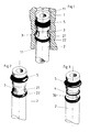
- the plug connection shown in FIGS. 1, 2, 4 and 5 is formed by a plug part 2 formed on a round rod and a cutting ring 3 and a bore 11 arranged in a housing 1.
- an annular groove 23 is initially formed for receiving a sealing ring 5.
- an annular recess 21 or Groove is provided in the lateral surface of the plug-in part 2, the recess in the upper region having a conical base 210 which ends at an abutment shoulder 35.
- the cutting ring 3 is provided with a longitudinal slot 34.
- the cutting ring 3 can be slipped radially over the recess 21.
- the longitudinal slot 34 is dimensioned such that there is a slight elastic expansion when slipping on, so that the cutting ring 3 is captively carried by the recess 21 of the plug-in part 2 after slipping on.
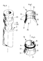
- the cutting ring 3 also has an approximately cylindrical region 32 and an approximately conical region 33, on the outer edge of which the cutting edge 31 is formed.
- the cutting ring 3 is slipped on radially in the region of the recess 21, the cutting ring 3 is radially expanded in the region of the cutting edge 31 by the elastomer spring 22. If the plug-in part 2 according to FIG. 2 is then inserted into the bore 11 of the housing 1, the sealing ring 5 first reaches a secure seal in the undamaged region of the wall of the bore 11. Then the cutting ring 3 is pressed with the cutting edge 31 by the elastomer spring 22 against the wall of the bore 11.
- the plug-in part 2 After the plug-in part 2 has been completely inserted into the bore 11, it is no longer possible to pull it out or push it out due to the fluid pressure present, since when it is pulled out the cutting edge 31 from the elastomer spring 22 and the conical base 210 in the recess 21 radially into the wall the hole 11 is pressed and claws here, as can be seen from Figure 1 of the drawing.
- the elastomer spring 22 can also be used to seal off the recess 21 and the cutting ring 3 in the housing 1.
- a two-part cutting ring 30 is provided instead of a one-part cutting ring.
- the two parts of the cutting ring 30 are held by a rubber-elastic ring 4 in the recess 21 of the plug part 2. Otherwise, this embodiment corresponds to the first embodiment.
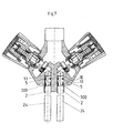
- FIGS. 7 to 10 show a connection of copper pipes of approximately 10 mm in diameter to a housing 10 of a sanitary single-hole water mixer tap.
- the copper tubes 24 are used for connection to the cold and hot water supply network and each have a plug-in part 2.
- a sealing ring 5 is provided at the front area of the plug-in part 2.
- the plug-in part 2 is provided with an annular groove 23 and a recess 21 with a conical base 210 by non-cutting deformation (beads).
- the cutting ring 300 is formed in one piece with a longitudinal slot 34 for slipping over the recess 21.
- the conical base 210 has an angle 25 of approximately 10 °.
- a correspondingly designed conical bore 36 is provided, so that after the insertion of the plug-in part 2 into the bore 11 of the housing 10 after a withdrawal or push back by the fluid pressure, the cutting ring 300 is expanded radially, as a result of which the cutting edge 31 into the wall the hole 11 penetrates and prevents pulling or pressing the plug-in part 2.
- the diameter of the cutting edge 31 is expediently slightly larger than the diameter of the bore 11, so that it is pressed against the wall of the bore 11 by the elastic spring action of the ring.
- the cutting ring 3,30,300 can advantageously be made of stainless steel.
Landscapes
- Engineering & Computer Science (AREA)
- General Engineering & Computer Science (AREA)
- Mechanical Engineering (AREA)
- Health & Medical Sciences (AREA)
- Life Sciences & Earth Sciences (AREA)
- Hydrology & Water Resources (AREA)
- Public Health (AREA)
- Water Supply & Treatment (AREA)
- Quick-Acting Or Multi-Walled Pipe Joints (AREA)
- Joints With Sleeves (AREA)
- Mechanical Coupling Of Light Guides (AREA)
- Pens And Brushes (AREA)
- Infusion, Injection, And Reservoir Apparatuses (AREA)
- Surgical Instruments (AREA)
- Connector Housings Or Holding Contact Members (AREA)
- External Artificial Organs (AREA)
Abstract
Description
- Die Erfindung betrifft eine Verbindung eines Rundstabes, Rohrs o.dgl. mit einem Gehäuse, insbesondere Sanitärarmatur, wobei wenigstens eine Elastomerdichtung und ein Schneidring zur Sicherung in der Verbindungslage vorgesehen ist. Eine derartige Verbindung ist aus der DE-OS 16 50 012 bekannt. Bei dieser Verbindung ist allerdings eine besondere Überwurfmutterverschraubung erforderlich, so daß diese Verbindungsform als verhältnismäßig aufwendig anzusehen ist. Darüber hinaus benötigt die Überwurfmutter relativ viel Raum, der häufig bei Anschlußverbindungen an Gehäuse, insbesondere bei Sanitärarmaturen mit Einsockelbefestigung, nicht vorhanden ist. Es ist daher bereits aus der DE 38 11 357 AI bekannt, die Anschlußrohre in dem Batteriekörper mit einem Preßsitz nach der Fertigstellung der Armatur einzusetzen. Hierbei ist es jedoch erforderlich, daß enge Toleranzen im Anschlußbereich der Rohrleitungen und der Bohrungen im Gehäuse eingehalten werden. Darüber hinaus wird eine relativ aufwendige Einrichtung zum Tiefkühlen der einzusetzenden Rohrstücke benötigt.
- Der Erfindung liegt die Aufgabe Zugrunde, eine einfache und kostengünstig herzustellende, wenig Raum benötigende Steckverbindung zu schaffen, die eine im wesentlichen unlösbare Verbindung nach dem Zusammenfügen gewährleistet.
- Diese Aufgabe wird erfindungsgemäß dadurch gelöst, daß der Rundstab oder das Rohr mit einem Steckteil versehen ist, das in eine Bohrung des Gehäuses einschiebbar ist, wobei in einer ringförmigen Ausnehmung eine Rückzugsperre in Form eines Schneidrings angeordnet ist, der sich bei umgekehrter Axialbewegung des Steckteils mit einer oder mehreren Schneidkanten in der Wandung der Bohrung verkrallt, so daß eine Verriegelung in der Stecklage erfolgt.
- Weitere Ausgestaltungen der Erfindung sind in den Ansprüchen 2 bis 10 angegeben.
- Die mit der Erfindung erzielbaren Vorteile bestehen insbesondere darin, daß die Steckverbindung ohne besondere Werkzeuge und Einrichtungen zu jeder Zeit zusammengefügt werden kann, worauf dann eine unlösbare Verbindung zwischen dem Gehäuse und dem Rundstab oder Rohr entsteht. Für die Verbindung wird kein größerer Raum benötigt als für das einzuführende Steckteil selbst. Mit der erfindunggemäßen Steckverbindung kann insbesondere die Herstellung und Montage von sanitären Wassereinlochmischbatterien vereinfacht werden. Diese Armaturen sind in der Regel so ausgebildet, daß sie am Befestigungssockel zwei Kupferrohre mit einem Durchmesser von etwa 10mm aufweisen für den Anschluß an das Kalt-und Warmwasserleitungsnetz. Mit Hilfe der erfindungsgemäßen Steckverbindung kann hierbei die Herstellung und Oberflächenveredelung des Sanitärarmaturengehäuses ohne die relativ sperrigen Anschlußrohre aus Kupfer durchgeführt werden. Die Fertigmontage der Wasserleitungsarmatur ist ohne die sperrigen Kupferrohre einfacher durchzuführen. Außerdem sind kleinere Verpackungseinheiten für die Sanitärarmaturen ohne Kupferrohre möglich, wodurch weiterhin ein geringeres Lagervolumen und ein geringeres Transportvolumen erreicht wird. Schließlich ermöglicht die erfindungsgemäße Steckverbindung, daß die sanitäre Wasserarmatur zunächst ohne Kupferrohre auf dem Waschtisch oder Spültisch montiert wird und danach die Kupferröhrchen einfach in die Bohrungen des Sanitärarmaturenkörpers eingesteckt werden, wodurch dann eine unlösbare, dichte Verbindung herstellbar ist.
- Ausführungsbeispiele der Erfindung sind in der Zeichnung dargestellt und werden im folgenden näher beschrieben. Es zeigt
- Figur 1 eine Steckverbindung eines Rundstabes mit einem Gehäuse im Längsschnitt;
- Figur 2 den Rundstab gemäß Figur 1 in Perspektivansicht mit einem einteiligen Schneidring;
- Figur 3 den Rundstab gemäß Figur 1 in Perspektivansicht mit einem zweiteiligen Schneidring;
- Figur 4 das Steckteil des Rundstabes gemäß Figur 1 in Perspektivansicht in vergrößerter Darstellung;
- Figur 5 den in den Figuren 1 und 2 gezeigten Schneidring in Perspektivansicht in vergrößerter Darstellung;
- Figur 6 den in Figur 3 dargestellten Schneidring in Perspektivansicht in vergrößerter Darstellung;
- Figur 7 eine sanitäre Einlochwassermischbatterie im Längsschnitt;
- Figur 8 das in Figur 7 dargestellte Kupferrohr in vergrößerter Darstellung teilweise geschnitten;
- Figur 9 den in Figur 7 dargestellten Schneidring in vergrößerter Darstellung;
- Figur 10 den in Figur 9 gezeigten Schneidring in Draufsicht.
- Der Einfachheit halber sind bei den Ausführungsbeispielen in der Zeichnung gleiche oder entsprechende Elemente mit jeweils gleichen Bezugszeichen versehen. Die in den Figuren 1, 2, 4 und 5 gezeigte Steckverbindung wird von einem an einem Rundstab ausgebildeten Steckteil 2 und einem Schneidring 3 und einer in einem Gehäuse 1 angeordneten Bohrung 11 gebildet. Im Bereich der Spitze des Steckteils 2 ist zunächst eine Ringnut 23 für die Aufnahme eines Dichtrings 5 ausgebildet. Dahinter ist eine ringförmige Ausnehmung 21 oder Kehlung in der Mantelfläche des Steckteils 2 vorgesehen, wobei die Ausnehmung im oberen Bereich einen kegelförmigen Grund 210 aufweist, der an einer Anlageschulter 35 endet. Der Schneidring 3 ist, wie es insbesondere aus Figur 5 zu entnehmen ist, mit einem Längsschlitz 34 versehen. Dadurch kann der Schneidring 3 radial über die Ausnehmung 21 übergestreift werden. Der Längsschlitz 34 ist dabei so bemessen, daß beim Überstreifen eine geringe elastische Aufweitung erfolgt, so daß der Schneidring 3 nach dem Überstreifen unverlierbar von der Ausnehmung 21 des Steckteils 2 getragen wird. Der Schneidring 3 weist ferner einen etwa zylindrischen Bereich 32 und einen etwa konischen Bereich 33, an dessen äußeren Rand die Schneidkante 31 ausgebildet ist, auf. Bevor der Schneidring 3 über den in Figur 4 gezeigten Steckteil 2 übergestreift wird, wird in der Ringnut 23 ein Dichtring 5 und im unteren Bereich der Ausnehmung 21 eine Elastomerfeder 22, z.B. Gummiring, eingelegt, wie es z.B. aus Figur 2 zu entnehmen ist. Wird nun der Schneidring 3 radial im Bereich der Ausnehmung 21 übergestreift, so erfährt der Schneidring 3 im Bereich der Schneidkante 31 durch die Elastomerfeder 22 eine radiale Aufweitung. Wird danach das Steckteil 2 gemäß Figur 2 in die Bohrung 11 des Gehäuses 1 eingeführt, so gelangt zunächst der Dichtring 5 im unbeschädigten Bereich der Wandung der Bohrung 11 zur sicheren Abdichtung. Danach wird der Schneidring 3 mit der Schneidkante 31 von der Elastomerfeder 22 gegen die Wandung der Bohrung 11 gedrückt. Nachdem das Steckteil 2 völlig in die Bohrung 11 eingeschoben worden ist, ist ein Herausziehen oder ein Herausschieben durch den anstehenden Fluiddruck nicht mehr möglich, da beim Herausziehen die Schneidkante 31 von der Elastomerfeder 22 und dem kegelförmigen Grund 210 in der Ausnehmung 21 radial in die Wandung der Bohrung 11 gedrückt wird und sich hier verkrallt, wie es aus Figur 1 der Zeichnung zu entnehmen ist. Mit der Elastomerfeder 22 kann zusätzlich noch eine Abdichtung zur Ausnehmung 21 und dem Schneidring 3 im Gehäuse 1 erfolgen.
- Bei dem in Figur 3 und 6 gezeigten Ausführungsbeispiel ist anstatt eines einteiligen Schneidrings ein zweiteiliger Schneidring 30 vorgesehen. Die beiden Teile des Schneidrings 30 werden dabei von einem gummielastischen Ring 4 in der Ausnehmung 21 des Steckteils 2 gehalten. Im übrigen entspricht diese Ausführung dem ersten Ausführungsbeispiel.
- In den Figuren 7 bis 10 ist eine Verbindung von Kupferrohren von etwa 10mm Durchmesser mit einem Gehäuse 10 einer sanitären Einlochwassermischbatterie gezeigt. Die Kupferrohre 24 dienen dabei zum Anschluß an das Kalt- und Warmwasserversorgungsnetz und weisen jeweils ein Steckteil 2 auf. Am vorderen Bereich des Steckteils 2 ist jeweils ein Dichtring 5 zur Abdichtung zwischen der Wandung der Bohrung 11 und dem Steckteil 2 vorgesehen. Wie es insbesondere aus Figur 8 zu entnehmen ist, ist das Steckteil 2 durch spanlose Verformung (Sicken) mit einer Ringnut 23 und einer Ausnehmung 21 mit einem kegelförmigen Grund 210 versehen. Wie es insbesondere aus Figur 9 und 10 zu entnehmen ist, ist der Schneidring 300 einstückig mit einem Längsschlitz 34 zum Überstreifen über die Ausnehmung 21 ausgebildet. Der kegelförmige Grund 210 weist einen Winkel 25 von etwa 10° auf. In dem Schneidring 300 ist eine entsprechend ausgebildete konische Bohrung 36 vorgesehen, so daß nach dem Einstecken des Steckteils 2 in die Bohrung 11 des Gehäuses 10 nach einem Zurückziehen oder Zurückdrücken durch den Fluiddruck der Schneidring 300 radial aufgeweitet wird, wodurch die Schneidkante 31 in die Wandung der Bohrung 11 eindringt und ein Herausziehen oder -pressen des Steckteils 2 verhindert. Zweckmäßig ist der Durchmesser der Schneidkante 31 geringfügig größer als der Durchmesser der Bohrung 11, so daß er durch die elastische Federwirkung des Ringes gegen die Wandung der Bohrung 11 gepreßt wird.
- Der Schneidring 3,30,300 kann vorteilhaft aus nichtrostendem Stahl hergestellt sein.
Claims (10)
Applications Claiming Priority (2)
| Application Number | Priority Date | Filing Date | Title |
|---|---|---|---|
| DE4026816A DE4026816A1 (de) | 1990-08-24 | 1990-08-24 | Steckverbindung |
| DE4026816 | 1990-08-24 |
Publications (2)
| Publication Number | Publication Date |
|---|---|
| EP0472022A1 true EP0472022A1 (de) | 1992-02-26 |
| EP0472022B1 EP0472022B1 (de) | 1994-05-18 |
Family
ID=6412852
Family Applications (1)
| Application Number | Title | Priority Date | Filing Date |
|---|---|---|---|
| EP91112932A Expired - Lifetime EP0472022B1 (de) | 1990-08-24 | 1991-08-01 | Steckverbindung |
Country Status (7)
| Country | Link |
|---|---|
| US (1) | US5213377A (de) |
| EP (1) | EP0472022B1 (de) |
| JP (1) | JPH04236888A (de) |
| AT (1) | ATE105893T1 (de) |
| DE (2) | DE4026816A1 (de) |
| DK (1) | DK0472022T3 (de) |
| ES (2) | ES1019324Y (de) |
Cited By (4)
| Publication number | Priority date | Publication date | Assignee | Title |
|---|---|---|---|---|
| DE9200696U1 (de) * | 1992-01-22 | 1992-04-16 | Huwil-Werke GmbH Möbelschloß- und Beschlagfabriken, 5207 Ruppichteroth | Verbindungsteil, insbesondere Eckverbinder für Hohlprofile |
| US5213377A (en) * | 1990-08-24 | 1993-05-25 | Friedrich Grohe Armaturenfabrik Gmbh & Co. | Coupling for seating a tube end in a fitting |
| DE19902397C1 (de) * | 1999-01-22 | 2000-07-20 | Hansa Metallwerke Ag | Sanitärarmatur, insbesondere Waschtischarmatur |
| DE19915526C1 (de) * | 1999-04-07 | 2000-08-03 | Hansa Metallwerke Ag | Sanitärarmatur |
Families Citing this family (6)
| Publication number | Priority date | Publication date | Assignee | Title |
|---|---|---|---|---|
| US5921592A (en) * | 1995-11-21 | 1999-07-13 | Talana Investments Limited | Duct joiner and retaining clip therefor |
| US6073972A (en) * | 1998-05-19 | 2000-06-13 | Emhart Inc. | Composite body faucet connection |
| JP5047410B2 (ja) * | 2000-03-31 | 2012-10-10 | オリンパス株式会社 | レンズ鏡筒 |
| DE10234206A1 (de) * | 2002-07-19 | 2004-01-29 | Hansgrohe Ag | Steckverbindung für Sanitärarmaturen |
| DE102009021527A1 (de) | 2009-05-15 | 2010-11-18 | Bayerische Motoren Werke Aktiengesellschaft | Leitungsverbindung |
| DE102022123992A1 (de) * | 2022-09-19 | 2024-03-21 | Neoperl Gmbh | Ventilkartusche |
Citations (4)
| Publication number | Priority date | Publication date | Assignee | Title |
|---|---|---|---|---|
| GB1077599A (en) * | 1965-07-16 | 1967-08-02 | Bernhard Leutenegger | Nipple for pipe joints |
| DE1800604A1 (de) * | 1967-10-03 | 1969-08-07 | Ahlstroem Oy | Eine Rohrverbindung |
| GB2091830A (en) * | 1981-01-23 | 1982-08-04 | Vfp Corp | Plastics tube fitting |
| DE8501282U1 (de) * | 1985-01-19 | 1986-05-22 | Knebel & Röttger GmbH & Co, 5860 Iserlohn | Vorrichtung an einer absperrbaren Wasserarmatur zur Verbindung letzterer mit einer Rohrleitung |
Family Cites Families (14)
| Publication number | Priority date | Publication date | Assignee | Title |
|---|---|---|---|---|
| US1429299A (en) * | 1921-09-23 | 1922-09-19 | Henry B Newhall | Bolt anchor |
| US2968851A (en) * | 1958-08-25 | 1961-01-24 | Hardy Gordon Warren | Cable and tube anchor |
| DE6927716U (de) * | 1969-07-04 | 1969-11-27 | Unionbau Ohg Gebrueder Schulte | Verbindungselement fuer holz- metall- oder kunststoffteile |
| GB1504962A (en) * | 1975-02-14 | 1978-03-22 | Dom Holdings Ltd | Expanding bolt-like fastening means |
| US4135745A (en) * | 1977-12-23 | 1979-01-23 | Ford Motor Company | Quick connect fluid fitting |
| DE3008962A1 (de) * | 1980-03-08 | 1981-09-17 | Y. Bargele & Sohn KG, 5510 Saarburg | Vorrichtung zum loesbaren anschliessen von leitungen |
| CH649145A5 (de) * | 1981-02-03 | 1985-04-30 | Contraves Ag | Steckmuffen-rohrverbindung. |
| DE3235059A1 (de) * | 1982-09-22 | 1984-03-22 | Armaturenfabrik Hermann Voss GmbH + Co, 5272 Wipperfürth | Steckkupplung fuer druckleitungen, insbesondere kunststoffleitungen fuer bremssysteme fuer kraftfahrzeuge |
| DE3322202C2 (de) * | 1983-06-21 | 1986-11-20 | Helmut 7518 Bretten Hackel | Vorrichtung zum Montieren oder Lösen einer kraft- und formschlüssigen Rohr-Steckverbindung |
| US4610468A (en) * | 1984-08-14 | 1986-09-09 | United Technologies Automotive, Inc. | Quick connect/disconnect coupling |
| DE3731818A1 (de) * | 1987-09-22 | 1989-03-30 | Hilti Ag | Spreizduebel |
| DE3811357A1 (de) * | 1988-04-02 | 1989-10-19 | Grohe Armaturen Friedrich | Rohranschluss fuer wasserarmaturen |
| DE3835300A1 (de) * | 1988-10-17 | 1990-04-19 | Hilti Ag | Spreizanker |
| DE4026816A1 (de) * | 1990-08-24 | 1992-02-27 | Grohe Armaturen Friedrich | Steckverbindung |
-
1990
- 1990-08-24 DE DE4026816A patent/DE4026816A1/de not_active Withdrawn
-
1991
- 1991-06-26 ES ES19919102038U patent/ES1019324Y/es not_active Expired - Lifetime
- 1991-07-02 JP JP3161798A patent/JPH04236888A/ja active Pending
- 1991-08-01 DE DE59101657T patent/DE59101657D1/de not_active Expired - Fee Related
- 1991-08-01 ES ES91112932T patent/ES2056532T3/es not_active Expired - Lifetime
- 1991-08-01 EP EP91112932A patent/EP0472022B1/de not_active Expired - Lifetime
- 1991-08-01 AT AT91112932T patent/ATE105893T1/de active
- 1991-08-01 DK DK91112932.8T patent/DK0472022T3/da active
- 1991-08-23 US US07/749,164 patent/US5213377A/en not_active Expired - Fee Related
Patent Citations (4)
| Publication number | Priority date | Publication date | Assignee | Title |
|---|---|---|---|---|
| GB1077599A (en) * | 1965-07-16 | 1967-08-02 | Bernhard Leutenegger | Nipple for pipe joints |
| DE1800604A1 (de) * | 1967-10-03 | 1969-08-07 | Ahlstroem Oy | Eine Rohrverbindung |
| GB2091830A (en) * | 1981-01-23 | 1982-08-04 | Vfp Corp | Plastics tube fitting |
| DE8501282U1 (de) * | 1985-01-19 | 1986-05-22 | Knebel & Röttger GmbH & Co, 5860 Iserlohn | Vorrichtung an einer absperrbaren Wasserarmatur zur Verbindung letzterer mit einer Rohrleitung |
Cited By (6)
| Publication number | Priority date | Publication date | Assignee | Title |
|---|---|---|---|---|
| US5213377A (en) * | 1990-08-24 | 1993-05-25 | Friedrich Grohe Armaturenfabrik Gmbh & Co. | Coupling for seating a tube end in a fitting |
| DE9200696U1 (de) * | 1992-01-22 | 1992-04-16 | Huwil-Werke GmbH Möbelschloß- und Beschlagfabriken, 5207 Ruppichteroth | Verbindungsteil, insbesondere Eckverbinder für Hohlprofile |
| DE19902397C1 (de) * | 1999-01-22 | 2000-07-20 | Hansa Metallwerke Ag | Sanitärarmatur, insbesondere Waschtischarmatur |
| EP1022500A2 (de) | 1999-01-22 | 2000-07-26 | Hansa Metallwerke Ag | Sanitärarmatur, insbesondere Waschtischarmatur |
| DE19915526C1 (de) * | 1999-04-07 | 2000-08-03 | Hansa Metallwerke Ag | Sanitärarmatur |
| EP1043451A1 (de) * | 1999-04-07 | 2000-10-11 | Hansa Metallwerke Ag | Sanitärarmatur |
Also Published As
| Publication number | Publication date |
|---|---|
| ES1019324U (es) | 1992-03-16 |
| JPH04236888A (ja) | 1992-08-25 |
| DE4026816A1 (de) | 1992-02-27 |
| ES1019324Y (es) | 1992-11-01 |
| DE59101657D1 (de) | 1994-06-23 |
| ES2056532T3 (es) | 1994-10-01 |
| EP0472022B1 (de) | 1994-05-18 |
| DK0472022T3 (da) | 1994-09-19 |
| ATE105893T1 (de) | 1994-06-15 |
| US5213377A (en) | 1993-05-25 |
Similar Documents
| Publication | Publication Date | Title |
|---|---|---|
| EP1359361B1 (de) | Rohrkupplung für Rohrleitungen | |
| DE69212793T2 (de) | Verbindungsvorrichtung für Teile eines Fluid-Verteilungssystems, besagte Teile und System | |
| DE19653257C2 (de) | Zum Anschluß eines Schlauches mit einem zweiten Bauteil vorgesehene Schlauchkupplung | |
| EP0519244B1 (de) | Lösbare Rohranschlussverbindung | |
| DE19654435C2 (de) | Anordnung zur steckbaren Verbindung von Rohren oder Schläuchen mit Armaturen oder Fittings | |
| DE2856069A1 (de) | Anschlussvorrichtung fuer bremsleitungen unter verwendung eines adapters | |
| DE2832614A1 (de) | Verbindungsstueck fuer rohrleitungen | |
| DE2939081A1 (de) | Schnellkupplung fuer kunststoffrohre | |
| DE10139899A1 (de) | Kunststoffwellrohranordnung | |
| DE2622269B2 (de) | Anschlußeinrichtung zwischen einem Kunststoffrohr und einem stationären Anschlußstutzen | |
| DE2921568A1 (de) | Steckverbindungs-anschlusstueck fuer druckluftbremsanlagen | |
| DE69521057T2 (de) | Schnellkupplung mit schraubenfederring | |
| AT3080U1 (de) | Vorrichtung zum verbinden eines rohrstutzens, rohrförmigen armaturenteils oder fittings mit einem rohr | |
| DE19702289C2 (de) | Anordnung zur Verbindung von Rohren oder Schläuchen mit Armaturen oder Fittings | |
| EP0472022A1 (de) | Steckverbindung | |
| DE29621046U1 (de) | Anschlußsteckvorrichtung für Kunststoffrohre | |
| DE3923579A1 (de) | Anschlussarmatur fuer rohre, insbesondere fuer kunststoffrohre | |
| DE19852395C2 (de) | Steckkupplung | |
| DE60018748T2 (de) | Schnellkupplung mit erhöhtem Diffusionswiderstand für die Verbindung von Schlauch- und Rohrleitungen | |
| CH581273A5 (en) | Snap connection between hose ends - has inner and outer sleeves with O-ring seal and finger with ridge and groove | |
| DE2222290A1 (de) | Muffenverbindung fuer rohre, armaturen oder dgl | |
| CH690338A5 (de) | Verbindungs- und Anschlussstuck fur Wellrohre. | |
| EP1770320B1 (de) | Lösbare Steckverbindung für Rohrleitungen | |
| DE3221518C2 (de) | Fittinge zum automatischen Verbinden von Leitungen in pneumatischen oder hydraulischen Kreisen | |
| DE3325350C2 (de) |
Legal Events
| Date | Code | Title | Description |
|---|---|---|---|
| PUAI | Public reference made under article 153(3) epc to a published international application that has entered the european phase |
Free format text: ORIGINAL CODE: 0009012 |
|
| AK | Designated contracting states |
Kind code of ref document: A1 Designated state(s): AT CH DE DK ES FR GB IT LI NL SE |
|
| RAP1 | Party data changed (applicant data changed or rights of an application transferred) |
Owner name: FRIEDRICH GROHE AKTIENGESELLSCHAFT |
|
| 17P | Request for examination filed |
Effective date: 19920413 |
|
| 17Q | First examination report despatched |
Effective date: 19920702 |
|
| GRAA | (expected) grant |
Free format text: ORIGINAL CODE: 0009210 |
|
| AK | Designated contracting states |
Kind code of ref document: B1 Designated state(s): AT CH DE DK ES FR GB IT LI NL SE |
|
| PG25 | Lapsed in a contracting state [announced via postgrant information from national office to epo] |
Ref country code: NL Effective date: 19940518 |
|
| REF | Corresponds to: |
Ref document number: 105893 Country of ref document: AT Date of ref document: 19940615 Kind code of ref document: T |
|
| REF | Corresponds to: |
Ref document number: 59101657 Country of ref document: DE Date of ref document: 19940623 |
|
| PG25 | Lapsed in a contracting state [announced via postgrant information from national office to epo] |
Ref country code: AT Effective date: 19940801 |
|
| ITF | It: translation for a ep patent filed | ||
| ET | Fr: translation filed | ||
| PG25 | Lapsed in a contracting state [announced via postgrant information from national office to epo] |
Ref country code: LI Effective date: 19940831 Ref country code: CH Effective date: 19940831 |
|
| REG | Reference to a national code |
Ref country code: DK Ref legal event code: T3 |
|
| GBT | Gb: translation of ep patent filed (gb section 77(6)(a)/1977) |
Effective date: 19940823 |
|
| REG | Reference to a national code |
Ref country code: ES Ref legal event code: FG2A Ref document number: 2056532 Country of ref document: ES Kind code of ref document: T3 |
|
| NLV1 | Nl: lapsed or annulled due to failure to fulfill the requirements of art. 29p and 29m of the patents act | ||
| EAL | Se: european patent in force in sweden |
Ref document number: 91112932.8 |
|
| PLBE | No opposition filed within time limit |
Free format text: ORIGINAL CODE: 0009261 |
|
| STAA | Information on the status of an ep patent application or granted ep patent |
Free format text: STATUS: NO OPPOSITION FILED WITHIN TIME LIMIT |
|
| REG | Reference to a national code |
Ref country code: CH Ref legal event code: PL |
|
| 26N | No opposition filed | ||
| PGFP | Annual fee paid to national office [announced via postgrant information from national office to epo] |
Ref country code: SE Payment date: 19990726 Year of fee payment: 9 |
|
| PGFP | Annual fee paid to national office [announced via postgrant information from national office to epo] |
Ref country code: GB Payment date: 19990728 Year of fee payment: 9 |
|
| PGFP | Annual fee paid to national office [announced via postgrant information from national office to epo] |
Ref country code: DK Payment date: 19990823 Year of fee payment: 9 |
|
| PGFP | Annual fee paid to national office [announced via postgrant information from national office to epo] |
Ref country code: ES Payment date: 19990827 Year of fee payment: 9 |
|
| PGFP | Annual fee paid to national office [announced via postgrant information from national office to epo] |
Ref country code: FR Payment date: 19990830 Year of fee payment: 9 |
|
| PG25 | Lapsed in a contracting state [announced via postgrant information from national office to epo] |
Ref country code: GB Free format text: LAPSE BECAUSE OF NON-PAYMENT OF DUE FEES Effective date: 20000801 Ref country code: DK Free format text: LAPSE BECAUSE OF NON-PAYMENT OF DUE FEES Effective date: 20000801 |
|
| PG25 | Lapsed in a contracting state [announced via postgrant information from national office to epo] |
Ref country code: SE Free format text: LAPSE BECAUSE OF NON-PAYMENT OF DUE FEES Effective date: 20000802 Ref country code: ES Free format text: LAPSE BECAUSE OF NON-PAYMENT OF DUE FEES Effective date: 20000802 |
|
| REG | Reference to a national code |
Ref country code: FR Ref legal event code: CJ |
|
| GBPC | Gb: european patent ceased through non-payment of renewal fee |
Effective date: 20000801 |
|
| EUG | Se: european patent has lapsed |
Ref document number: 91112932.8 |
|
| PG25 | Lapsed in a contracting state [announced via postgrant information from national office to epo] |
Ref country code: FR Free format text: LAPSE BECAUSE OF NON-PAYMENT OF DUE FEES Effective date: 20010430 |
|
| REG | Reference to a national code |
Ref country code: DK Ref legal event code: EBP |
|
| REG | Reference to a national code |
Ref country code: FR Ref legal event code: ST |
|
| REG | Reference to a national code |
Ref country code: ES Ref legal event code: PC2A |
|
| PGFP | Annual fee paid to national office [announced via postgrant information from national office to epo] |
Ref country code: DE Payment date: 20020813 Year of fee payment: 12 |
|
| PG25 | Lapsed in a contracting state [announced via postgrant information from national office to epo] |
Ref country code: DE Free format text: LAPSE BECAUSE OF NON-PAYMENT OF DUE FEES Effective date: 20040302 |
|
| REG | Reference to a national code |
Ref country code: ES Ref legal event code: FD2A Effective date: 20010911 |
|
| PG25 | Lapsed in a contracting state [announced via postgrant information from national office to epo] |
Ref country code: IT Free format text: LAPSE BECAUSE OF NON-PAYMENT OF DUE FEES Effective date: 20050801 |