EP0472024A2 - Système de radar à impulsions - Google Patents
Système de radar à impulsions Download PDFInfo
- Publication number
- EP0472024A2 EP0472024A2 EP91112964A EP91112964A EP0472024A2 EP 0472024 A2 EP0472024 A2 EP 0472024A2 EP 91112964 A EP91112964 A EP 91112964A EP 91112964 A EP91112964 A EP 91112964A EP 0472024 A2 EP0472024 A2 EP 0472024A2
- Authority
- EP
- European Patent Office
- Prior art keywords
- digital
- channel
- pulse
- analog
- radar system
- Prior art date
- Legal status (The legal status is an assumption and is not a legal conclusion. Google has not performed a legal analysis and makes no representation as to the accuracy of the status listed.)
- Withdrawn
Links
- 230000005540 biological transmission Effects 0.000 claims abstract description 13
- 230000015654 memory Effects 0.000 claims abstract description 7
- 238000006243 chemical reaction Methods 0.000 claims abstract description 5
- 230000006835 compression Effects 0.000 claims description 13
- 238000007906 compression Methods 0.000 claims description 13
- 238000011156 evaluation Methods 0.000 claims description 4
- 230000002596 correlated effect Effects 0.000 claims description 2
- 230000004044 response Effects 0.000 claims 1
- 238000010586 diagram Methods 0.000 description 6
- 230000010363 phase shift Effects 0.000 description 4
- 238000011161 development Methods 0.000 description 1
- 230000018109 developmental process Effects 0.000 description 1
- 230000000694 effects Effects 0.000 description 1
- 230000008030 elimination Effects 0.000 description 1
- 238000003379 elimination reaction Methods 0.000 description 1
- 238000000034 method Methods 0.000 description 1
- 238000005070 sampling Methods 0.000 description 1
- 230000035945 sensitivity Effects 0.000 description 1
- 238000001228 spectrum Methods 0.000 description 1
Images
Classifications
-
- G—PHYSICS
- G01—MEASURING; TESTING
- G01S—RADIO DIRECTION-FINDING; RADIO NAVIGATION; DETERMINING DISTANCE OR VELOCITY BY USE OF RADIO WAVES; LOCATING OR PRESENCE-DETECTING BY USE OF THE REFLECTION OR RERADIATION OF RADIO WAVES; ANALOGOUS ARRANGEMENTS USING OTHER WAVES
- G01S13/00—Systems using the reflection or reradiation of radio waves, e.g. radar systems; Analogous systems using reflection or reradiation of waves whose nature or wavelength is irrelevant or unspecified
- G01S13/02—Systems using reflection of radio waves, e.g. primary radar systems; Analogous systems
- G01S13/06—Systems determining position data of a target
- G01S13/08—Systems for measuring distance only
- G01S13/10—Systems for measuring distance only using transmission of interrupted, pulse modulated waves
- G01S13/26—Systems for measuring distance only using transmission of interrupted, pulse modulated waves wherein the transmitted pulses use a frequency- or phase-modulated carrier wave
- G01S13/28—Systems for measuring distance only using transmission of interrupted, pulse modulated waves wherein the transmitted pulses use a frequency- or phase-modulated carrier wave with time compression of received pulses
- G01S13/282—Systems for measuring distance only using transmission of interrupted, pulse modulated waves wherein the transmitted pulses use a frequency- or phase-modulated carrier wave with time compression of received pulses using a frequency modulated carrier wave
Definitions
- the invention relates to a pulse radar system according to the preamble of patent claim 1.
- Pulse compression techniques have been used in pulse radar systems for many years in order to increase the resolution or the transmission power of the radar devices.
- the pulse compression technology also makes it possible to create radar systems that require lower peak transmission power while maintaining the same range.
- the sensitivity or the range can be increased by increasing the available energy per pulse by lengthening the transmission pulses.
- This affects the distance resolution, which is an important radar parameter.
- the distance resolution is directly related to the bandwidth of the radar pulse.
- Pulse compression systems are based on the idea of transmitting long, modulated pulses, but the pulse spectrum has the bandwidth of a signal train with short pulses.
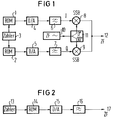
- the arrangement of a digital pulse expander previously used is shown in FIG. 1.
- the expanded signal which is fed to an IF transmission signal output 12, is generated in a single-sideband mixer consisting of two mixing stages 8 and 9.
- the IF carrier frequency is generated in an oscillator 7 and fed to the mixer 8 without a phase shift and to the mixer 9 with a phase shift of 90 degrees via a phase stage 11.
- the I and Q signals in the in-phase channel I and quadrature channel Q are read out from two read-only memories (ROMs) 1 and 2, which are supplied by a counter 3, and in digital / analog converters 4 and 5 implemented.
- a low-pass filter 6 is also interposed between converter 4 and the I-channel input at mixer stage 8.
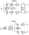
- the arrangement previously used for a digital pulse compressor on the receiving side is shown in FIG. 3.
- the received signal arriving at the IF carrier frequency level at an input 18 is demodulated analogously in two mixing stages 19 and 20.
- the IF oscillator frequency for downmixing is generated in an oscillator 21 and fed to the mixer 19 without a phase shift and to the mixer 20 via a phase link 22 with a 90 degree phase shift.
- This type of demodulation is used in digital signal processing in pulse radar technology Usual in-phase channel I and quadrature channel Q formed.
- the purpose of the quadrature channel is known to be the elimination of the effect of so-called blind phases.
- MI Skolnik pp. 119 to 121.
- the signals in the I-channel and Q-channel are each converted into digital signals in an analog / digital converter 23 or 24 in the baseband position and fed via a low-pass filter 25 or 26 to a complex correlator 27, of which the outputs 28 and 29 the I and Q signals can be taken for evaluation.
- the main problem with the implementation of the known, partly digitally operating pulse compressor is the high computing effort in the complex correlator 27.
- the object of the invention is to simplify the structure, in particular with regard to the reception-side correlator, in a pulse radar system with digital pulse expansion and digital pulse compression, and also to improve the properties as possible, in particular with regard to avoiding quadrature errors on the transmission and reception side.
- FIG. 2 shows a fully digital pulse expander of a pulse radar system according to the invention in a block diagram.
- the sample values of the modulated IF carrier are stored in a read-only memory (ROM) 14 supplied by a counter 13.
- a digital / analog converter 15 therefore generates the IF signal directly without frequency conversion.
- the analog intermediate frequency transmission signal is picked up via a low-pass filter 16 at an output 17.
- the outlay for the fully digital pulse expander shown in FIG. 2 is considerably less than in known digital pulse expander circuits, since only one digital / analog converter 15 is required.
- the level of the intermediate frequency that can be generated depends on the available sampling rate. Carrier frequencies up to approx. 20 MHz are no longer a problem today.
- FIG. 4 shows a fully digital pulse compressor of a pulse radar system according to the invention in block diagram form.
- the received signal picked up in the intermediate frequency level at an input 30 is first fed to an analog / digital converter 31.
- the digitized received signal is then input to a correlator 32 in the IF level.
- Correlator 32 thus no longer works in the baseband but in the carrier frequency level. Since the signals here are purely real, a complex correlator is no longer required. A real correlator is much simpler because it only requires one multiplier and one accumulator per stage.
- the correlated received signal in the IF level is then fed to an input of two digital mixing stages 34 and 35, the second input of which is each loaded by a read-only memory (ROM) 33.
- ROM read-only memory
- the output signals of the two mixer stages 34 and 35 mixed down to the baseband are fed to an output 38 in the I-channel via a low-pass filter 36 and to an output 39 in the Q-channel via a low-pass filter 37.
- the I and Q signals are then available at outputs 38 and 39 for further evaluation.
- An advantage of the fully digital pulse compressor according to FIG. 4 is that only one analog / digital converter 31 is required and that the quadrature errors are eliminated because of the digital quadrature demodulation.
- the processable carrier frequency depends on the level of the available clock rate of analog / digital converters and multipliers.
- carrier frequencies up to approx. 10 MHz can also be processed here, which will certainly be considerably higher in the future.
Landscapes
- Engineering & Computer Science (AREA)
- Radar, Positioning & Navigation (AREA)
- Remote Sensing (AREA)
- Computer Networks & Wireless Communication (AREA)
- Physics & Mathematics (AREA)
- General Physics & Mathematics (AREA)
- Radar Systems Or Details Thereof (AREA)
Applications Claiming Priority (2)
| Application Number | Priority Date | Filing Date | Title |
|---|---|---|---|
| DE4026854 | 1990-08-24 | ||
| DE4026854 | 1990-08-24 |
Publications (2)
| Publication Number | Publication Date |
|---|---|
| EP0472024A2 true EP0472024A2 (fr) | 1992-02-26 |
| EP0472024A3 EP0472024A3 (en) | 1992-08-19 |
Family
ID=6412871
Family Applications (1)
| Application Number | Title | Priority Date | Filing Date |
|---|---|---|---|
| EP19910112964 Withdrawn EP0472024A3 (en) | 1990-08-24 | 1991-08-01 | Pulse radar system |
Country Status (1)
| Country | Link |
|---|---|
| EP (1) | EP0472024A3 (fr) |
Cited By (4)
| Publication number | Priority date | Publication date | Assignee | Title |
|---|---|---|---|---|
| WO2003092183A3 (fr) * | 2002-04-10 | 2004-03-25 | Nanotron Technologies Gmbh | Dispositif emetteur-recepteur |
| WO2014123433A1 (fr) * | 2013-02-07 | 2014-08-14 | BUMAR ELEKTRONIBUMAR Spółka Akcyjna | Procédé et circuit de compression d'un signal radar |
| WO2017063724A1 (fr) | 2015-10-16 | 2017-04-20 | Oliver Bartels | Détermination de position par ondes radio à temporisation de grande précision dans le transpondeur |
| DE102016008390B3 (de) * | 2016-07-09 | 2017-05-24 | Oliver Bartels | Detektor für Chirp Impulse mit kurzer Latenzzeit und hoher zeitlicher Präzision |
Family Cites Families (5)
| Publication number | Priority date | Publication date | Assignee | Title |
|---|---|---|---|---|
| US3794995A (en) * | 1972-08-02 | 1974-02-26 | Raytheon Co | Modulation signal generator and apparatus using such generator |
| US3852746A (en) * | 1972-11-14 | 1974-12-03 | Raytheon Co | Pulse compression radar |
| DE3274936D1 (en) * | 1981-09-26 | 1987-02-05 | Bosch Gmbh Robert | Digital demodulator for frequency-modulated signals |
| US4560961A (en) * | 1983-01-26 | 1985-12-24 | Republic Electronics, Inc. | Method and means for generating pulse compression pulses |
| NL8304210A (nl) * | 1983-12-07 | 1985-07-01 | Hollandse Signaalapparaten Bv | Digitaal impulscompressiefilter. |
-
1991
- 1991-08-01 EP EP19910112964 patent/EP0472024A3/de not_active Withdrawn
Cited By (4)
| Publication number | Priority date | Publication date | Assignee | Title |
|---|---|---|---|---|
| WO2003092183A3 (fr) * | 2002-04-10 | 2004-03-25 | Nanotron Technologies Gmbh | Dispositif emetteur-recepteur |
| WO2014123433A1 (fr) * | 2013-02-07 | 2014-08-14 | BUMAR ELEKTRONIBUMAR Spółka Akcyjna | Procédé et circuit de compression d'un signal radar |
| WO2017063724A1 (fr) | 2015-10-16 | 2017-04-20 | Oliver Bartels | Détermination de position par ondes radio à temporisation de grande précision dans le transpondeur |
| DE102016008390B3 (de) * | 2016-07-09 | 2017-05-24 | Oliver Bartels | Detektor für Chirp Impulse mit kurzer Latenzzeit und hoher zeitlicher Präzision |
Also Published As
| Publication number | Publication date |
|---|---|
| EP0472024A3 (en) | 1992-08-19 |
Similar Documents
| Publication | Publication Date | Title |
|---|---|---|
| EP0080014B1 (fr) | Démodulateur numérique pour signaux modulés en fréquence | |
| DE69826829T2 (de) | Digitales kommunikationsgerät | |
| DE69735335T2 (de) | Wegnahme des DC-Offsets und Unterdrückung von verfälschten AM-Signalen in einem Direktumwandlungsempfänger | |
| DE69501996T2 (de) | Verfahren und vorrichtung zur automatischer verstarkungsregelung und gleidspannungs-offsetunterdruckung in einem quadraturempfanger | |
| EP0597255B1 (fr) | Récepteur pour radiodiffusion numérique avec traitement numérique de signaux | |
| DE60310569T2 (de) | Mischeranordnung unter verwendung von einigen oszillatoren und darauf basierenden systemen | |
| DE69320126T2 (de) | Burststeuerung in einem Leistungsverstärker für TOMA-Übertragungssystem | |
| DE1616439B1 (de) | Verfahren und Schaltungsanordnungen zur Signalumwandlung | |
| DE19713102A1 (de) | Integrierte Empfangsschaltung für Mobiltelefon | |
| DE4219417C2 (de) | Schmalbandempfänger für Datensignale | |
| DE3145919A1 (de) | Verfahren und anordnung zum demodulieren zeitdiskreter frequenzmodulierter signale | |
| DE69628130T2 (de) | Digitales Schmalbandfilter | |
| EP0472024A2 (fr) | Système de radar à impulsions | |
| DE69837002T2 (de) | Verzögerungskompensierungseinrichtung einer linearisationsschleife eines leistungsverstärkers | |
| DE3733967C2 (fr) | ||
| DE69926064T2 (de) | Drei-Tor Struktur mit modulierten Injektionssignal | |
| EP0755125B1 (fr) | Procédé pour la réduction des postes supplémentaires de réception dans des récepteurs homodynes avec la fréquence porteuse variable en temps | |
| DE10027389B4 (de) | Verfahren zur Synchronisation | |
| DE3425782A1 (de) | Fm-demodulation durch digitale verzoegerung und autokorrelation | |
| DE10000958B4 (de) | Schaltungsanordnung zur Erzeugung eines quadraturamplitudenmodulierten Sendesignals | |
| EP0499827B1 (fr) | Autoradio comprenant un circuit de conversion Analogue/Numérique du signal à fréquence intermediaire | |
| DE3636630C1 (en) | Single channel radio direction finder | |
| DE1932291A1 (de) | Frequenzumsetzer | |
| DE3428318C2 (fr) | ||
| EP0002790B1 (fr) | Appareil de mesure pour l'analyse en fréquence des niveaux de signaux électriques dans une large gamme d'amplitudes |
Legal Events
| Date | Code | Title | Description |
|---|---|---|---|
| PUAI | Public reference made under article 153(3) epc to a published international application that has entered the european phase |
Free format text: ORIGINAL CODE: 0009012 |
|
| AK | Designated contracting states |
Kind code of ref document: A2 Designated state(s): DE FR GB IT |
|
| PUAL | Search report despatched |
Free format text: ORIGINAL CODE: 0009013 |
|
| AK | Designated contracting states |
Kind code of ref document: A3 Designated state(s): DE FR GB IT |
|
| 17P | Request for examination filed |
Effective date: 19921007 |
|
| STAA | Information on the status of an ep patent application or granted ep patent |
Free format text: STATUS: THE APPLICATION IS DEEMED TO BE WITHDRAWN |
|
| 18D | Application deemed to be withdrawn |
Effective date: 19940301 |