EP0472267A2 - Système de convertisseur optimisé du type à 18 impulsions AC/DC, ou DC/AC - Google Patents
Système de convertisseur optimisé du type à 18 impulsions AC/DC, ou DC/AC Download PDFInfo
- Publication number
- EP0472267A2 EP0472267A2 EP91304991A EP91304991A EP0472267A2 EP 0472267 A2 EP0472267 A2 EP 0472267A2 EP 91304991 A EP91304991 A EP 91304991A EP 91304991 A EP91304991 A EP 91304991A EP 0472267 A2 EP0472267 A2 EP 0472267A2
- Authority
- EP
- European Patent Office
- Prior art keywords
- windings
- lines
- buses
- rectifier
- winding
- Prior art date
- Legal status (The legal status is an assumption and is not a legal conclusion. Google has not performed a legal analysis and makes no representation as to the accuracy of the status listed.)
- Granted
Links
Images


Classifications
-
- H—ELECTRICITY
- H02—GENERATION; CONVERSION OR DISTRIBUTION OF ELECTRIC POWER
- H02M—APPARATUS FOR CONVERSION BETWEEN AC AND AC, BETWEEN AC AND DC, OR BETWEEN DC AND DC, AND FOR USE WITH MAINS OR SIMILAR POWER SUPPLY SYSTEMS; CONVERSION OF DC OR AC INPUT POWER INTO SURGE OUTPUT POWER; CONTROL OR REGULATION THEREOF
- H02M7/00—Conversion of AC power input into DC power output; Conversion of DC power input into AC power output
- H02M7/02—Conversion of AC power input into DC power output without possibility of reversal
- H02M7/04—Conversion of AC power input into DC power output without possibility of reversal by static converters
- H02M7/12—Conversion of AC power input into DC power output without possibility of reversal by static converters using discharge tubes with control electrode or semiconductor devices with control electrode
- H02M7/145—Conversion of AC power input into DC power output without possibility of reversal by static converters using discharge tubes with control electrode or semiconductor devices with control electrode using devices of a thyratron or thyristor type requiring extinguishing means
- H02M7/155—Conversion of AC power input into DC power output without possibility of reversal by static converters using discharge tubes with control electrode or semiconductor devices with control electrode using devices of a thyratron or thyristor type requiring extinguishing means using semiconductor devices only
- H02M7/17—Conversion of AC power input into DC power output without possibility of reversal by static converters using discharge tubes with control electrode or semiconductor devices with control electrode using devices of a thyratron or thyristor type requiring extinguishing means using semiconductor devices only arranged for operation in parallel
Definitions
- the invention relates to static AC-to-DC converters, such as can be used for AC or DC motors.
- the present invention resides in an 18-pulse converter system which has optimized structural and functional characteristics. It involves three 6-pulse rectifier bridges directly connected in parallel with the DC terminals, two of the bridges operating under respective +40 degree and -40 degree phase shift relative to the AC lines, and the third or central bridge being directly connected to the AC lines, the rectifiers being controlled for 40-degree current conduction.
- the invention can be applied to five of such 3-phase rectifier bridges, for a 30-pulse system wherein the displacements are ⁇ 48°; ⁇ 24° relative to the central bridge.
- the invention is applicable, in the same vein, to a 7-bridge pulse system, to a nine-bridge pulse system, or more.
- the invention relates to an 18-pulse AC-to-DC converter arrangement using special autotransformer connections with an appropriate phase shift and a selected conduction angle in order to eliminate the need for interphase transformers.
- This arrangement when combined with appropriate AC line reactances, leads to the generation of input line harmonic currents in the AC lines which are easily reduced to less than 11 ⁇ 2% of the fundamental current, a substantial improvement over the prior art.
- the harmonic currents generated by an AC-to-DC converter must be reduced to values lower than those attainable with a 12-pulse arrangement, this particular 18-pulse design becomes desirable.
- This approach rests upon the observation that the idealized harmonic currents have frequencies of (18 k ⁇ 1) with amplitudes of 1/(18 k ⁇ 1).
- Prior art 18-pulse techniques have encountered practical connection difficulties because of the large rating of associated phase-shifting and interphase transformers.
- Three-phase rectifier bridge arrangements typically involve a single 3-pulse converter group combining three SCR devices, or 3 diodes, with a 120° period of current conduction. With this approach, however, there will be a need for an interphase transformer and for providing a neutral reference point between the bridges. The present invention no longer requires an interphase transformer, nor a neutral reference point between the rectifier bridges.
- a basic 3-phase rectifier group is shown which, because it lacks smoothing inductors on the DC side, allows a significant ripple amount on the DC load.
- This group includes three SCR devices T1, T2, T3 connected to the AC power supply lines L1, L2, L3 through inductances L. Their common junction point CM is connected to the positive DC terminal TA. The neutral return line is TN derived from the DC terminal TB. Between the two DC terminals are a capacitor C and a resistor R, as generally known. The system operates to convert AC power into DC power or, conversely, DC power into AC power, depending upon where the supply and the load is.
- the line currents are shown applied through the inductance L so as to limit the rate of change of current and provide some reduction in the line current harmonics.
- the AC currents such as il on Figure 1, contain a DC component and a significant amount of third harmonic current. Although this is a workable circuit, it is rarely used for higher power applications because of the distortion and the unfavorable loading exerted upon the supply.
- FIG. 2 shows two such "building blocks", T1, T2, T3, and T'1, T'2, T'3 with their common junction points CM, CM', respectively, and a common neutral point N (located between two capacitors C and C') for the return neutral line LN.
- This common neutral connection is used so as to eliminate the DC component in the supply. Nevertheless, there remains a large third harmonic component of current drawn from the AC source. By providing a neutral point N which does not return to the AC power supply, the third harmonic no longer circulates through the AC source.
- Figure 4 shows three 6-pulse rectifier bridges BR#1, BR#2 and BR#3, as disclosed in U.S. Patent No. 4,876,634.
- the rectifiers are controlled under 120-degree current conduction, and the bridges are staggered by a 20-degree phase shift regarding the incoming power supply voltages. They are interconnected at both ends with an interphase transformer--one with the positive DC terminal TP, the other with the negative DC terminal TN--as shown in Figure 4. This helps provide a common neutral point like with the approach of Figure 3.
- Figure 5 shows as prior art an 18-pulse converter disclosed in U.S. Patent No 4,876,634.
- This converter operates with a polygonal transformer placing each of the lines 1, 2, 3 (for bridge BR #3 ), 1', 2', 3' (for bridge BR #2 ) and 1'', 2'', 3'' (for bridge BR #1 ) at a relative phase shift of 20 degrees, and the SCR devices are controlled for 120 degrees of conduction.
- AC lines L1, L2, L3 are directly applied by lines 1, 2, 3 to a third rectifier bridge BR #3 .
- the AC side is with lines L1, L2, L3, whereas, the DC side is between terminals TA and TB at the common terminals of the bridges.
- transformer TNF interposed between the three bridges BR #1 , BR #2 , and BR #3 on one side and lines L1, L2, L3, on the other side.
- transformer TNF will provide + and -40° phase shifts between lines 1', 2', 3' to bridge BR #1 and lines 1'', 2'', 3'' to bridge BR #2 relative to a 0-degree phase shift for lines 1, 2, 3, from L1, L2, L3.
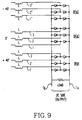
- each set of rectifier bridge has in common the same individual pairs of serially-connected rectifiers across the two DC terminals and with their midpoint connected to the incoming (or outgoing) AC line. All that is required is a filtering inductance L in order to eliminate any high frequency component on lines 1, 2, 3; 1', 2', 3'; and 1'', 2'', 3'' of the rectifier bridges.
- each line (1, 2, 3; 1', 2', 3'; 1'', 2'', 3'') carries an inductance L.
- two inductances L and L' are inserted on each side of the corresponding bridge and line between terminals TA and TB.
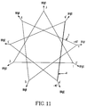
- Figure 11 is a diagram related to the first embodiment of the invention. It shows the voltage vector sets of two transformers (I at +40° phase shift, and II at -40° phase shift), the primary set being shown as a delta diagram at 0 degrees phase shift, thus, in between. Points 1, 2, 3 go to bridge BR #3 ; points 4', 5', 6' go to bridge BR #2 ; and points 4, 5, 6 go to bridge BR #1 .
- Figure 12 shows the voltage vectors associated with a single transformer approach in the case of a differential delta, which relates to the second embodiment of the invention.
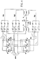
- a 18-pulse converter system is shown having the optimized design for such a system.
- points 4, 5, 6 at a phase shift of +40° and going to bridge BR #1 ; tappings 4', 5', 6' at a phase shift of -40° and going to bridge BR #2 .
- Figure 13 shows the three bridges-- BR #1 , BR #2 , BR #3 -- in parallel between the two DC terminals TA, TB and connected individually to the corresponding nine AC lines (1 to 9). There is no interphase transformer. In order to reduce the high frequency current, on each line has been interposed an inductor L, and on the DC side an inductor Ldc before the capacitor C, and a variable resistor Rdc which characterize the DC load.
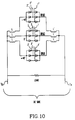
- Figure 14 is the differential delta transformer design matching the general diagram of Figure 12.
- WA, WB, WC, disposed about AC lines tappings I, G, H, are the central windings; in fact, the primary windings if the input comes from the AC side.
- the secondary windings for one of the two bridges, BR #1 and BR #2, are for +40° phase shift: W'A1 and W'B2 associated with tapping 3 (apex I) opposite to winding WA; W'C1 and W'A2 associated with tapping 2 (apex G) opposite to winding WC; and W'B1 and W'C2 for tapping 1 (apex H) opposite to winding WB.
- W'B2, W'A2 and W'C2 are coupled with windings WB, WA and WC, respectively, while windings W'A1, W'B1 and W'C1 are coupled to windings WA, WB, WC, respectively.
- the same can be said for the -40° phase shift pairs of windings WA1 and WC2 (apex I), WC1 and WB2 (apex G), WB1 and WA2 (apex H).
- the sizes of the windings are, typically, 58 turns for WA, WB or WC; 17 turns for WA1, W'A1, WB1, W'B1, WC1 and W'C1; 9 turns for WA2, W'A2, WB2, W'B2, WC2, W'C2.
- Another possible set of windings would be 65, 19 and 10 for the respective number of turns for the main, intermediate, and smallest windings.
- the third harmonic has a zero sequence, while no phase shift does occur as it passes through the transformer.
- the leading (+40°) converter will have third harmonic current at 3 x 40°, i.e. 120°
- the lag converter (-40°) will have third harmonic current at 3 X -40°, i.e. -120°.
- the 3-phase set of third harmonic currents cancels and there is no resultant third harmonic drawn from the source.
- the negative and positive sequence sets of 5, 7, 11, 13 harmonics are phase-shifted as they pass through the transformer.
- the negative sequence shifts through an angle opposite to that of the positive sequence.
- the phase shift, with respect to the source is (5 X 40°) +40°, i.e. 240°.
- the -40° shift transformer it is (5 X -40) -40°, i.e. -240°.
- the three sets of fifth harmonic currents sum to zero from the source. Similar reasoning leads to observe that there is also an elimination of the 7, 11, 13 harmonics.
- a 30-pulse converter system can be designed under the same principle by adding four instead of two symmetrically shifted bridges in conjunction with a bridge having no phase shift. In such case, two will be at + and -48 degrees phase shift, two will be at + and -24 degrees phase shift, and one will be at zero degree phase shift.
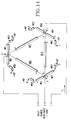
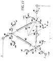
- Figure 17 is like Figure 14, but modified by the adjunction of a winding WD placed as an extension of each side (WA, WB, or WC) of the triangle GHI.
- the three AC lines 1, 2, 3 are connected to one end of the added windings WD, respectively, while the other end thereof is connected to an associated apex of the triangle. The effect is to reduce the DC output to the extent of the ampere-turns of the added winding WD.
- Figure 18 is like Figure 14, but instead of decreasing the DC output, a winding WD is added in such a way that the DC output is increased.
- the AC lines 1, 2, 3, instead of being connected directly to the respective apices of the triangle GHI, they are connected to a tapping of the main delta windings.
- a full delta winding WA, WB or WC as in Figure 14, such winding is merely a fraction of the main triangle winding, and the complementary fraction on the triangle is the winding WD of Figure 17, used now as a subtrahend.
- FIG 19 shows an alternative arrangement for the winding system of Figure 14, regarding the pairs of windings creating a 40° phase shift in either direction (W'C2, W'B1 and WB1, WA2 for tapping 1; W'A2, W'C1 and WC1, WB2 for tapping 2; or W'B2, W'A1 and WA1, WC2 for tapping 3).
- Windings WA2 and W'A2 which are closest to the main winding WA, to which they are coupled from either end, are now inserted between a corresponding end of WA and the associated apex of the main triangle. The same is done for WB2 and W'B2 regarding main winding WB, and also for WC2 and W'C2 regarding main winding WC.
- each pair thus the one (WB1 and W'B1 for apex H, or WC1 and W'C1 for apex G, or WA1 and W'A1 for apex I) which is remote from the main winding (WB, WC, or WA) to which it is coupled, is branched to the nodal point between the adjacent main winding (WA and WC for apex H, WB and WA for apex G and WC and WB for apex I), and the inserted winding (WA2 with WA for WB1, W'C2 with WC for W'B1; W'A2 with WA for W'C1, WB2 with WB for WC1, etc.).
- the embodiment of Figure 19 also shows a winding WD being inserted on each apex of the triangle with the respective AC lines 1, 2, 3.
Landscapes
- Engineering & Computer Science (AREA)
- Power Engineering (AREA)
- Rectifiers (AREA)
- Control Of Electrical Variables (AREA)
Applications Claiming Priority (4)
| Application Number | Priority Date | Filing Date | Title |
|---|---|---|---|
| US56910590A | 1990-08-17 | 1990-08-17 | |
| US569105 | 1990-08-17 | ||
| US674815 | 1991-03-22 | ||
| US07/674,815 US5124904A (en) | 1990-08-17 | 1991-03-22 | Optimized 18-pulse type AC/DC, or DC/AC, converter system |
Publications (3)
| Publication Number | Publication Date |
|---|---|
| EP0472267A2 true EP0472267A2 (fr) | 1992-02-26 |
| EP0472267A3 EP0472267A3 (en) | 1992-06-03 |
| EP0472267B1 EP0472267B1 (fr) | 1997-05-02 |
Family
ID=27074981
Family Applications (1)
| Application Number | Title | Priority Date | Filing Date |
|---|---|---|---|
| EP91304991A Expired - Lifetime EP0472267B1 (fr) | 1990-08-17 | 1991-06-03 | Système de convertisseur optimisé du type à 18 impulsions AC/DC, ou DC/AC |
Country Status (12)
| Country | Link |
|---|---|
| EP (1) | EP0472267B1 (fr) |
| JP (1) | JP3192168B2 (fr) |
| CN (1) | CN1030362C (fr) |
| AR (1) | AR244921A1 (fr) |
| AT (1) | ATE152555T1 (fr) |
| AU (1) | AU644153B2 (fr) |
| BR (1) | BR9102391A (fr) |
| CA (1) | CA2043064C (fr) |
| DE (1) | DE69125894T2 (fr) |
| ES (1) | ES2102387T3 (fr) |
| IE (1) | IE80543B1 (fr) |
| NZ (1) | NZ238280A (fr) |
Cited By (2)
| Publication number | Priority date | Publication date | Assignee | Title |
|---|---|---|---|---|
| US6660360B2 (en) | 2000-01-04 | 2003-12-09 | Cooper Technology Services, Llc | Laminate of a substrate and an extruded high density polyethylene |
| EP1622248A3 (fr) * | 2004-07-29 | 2008-03-05 | Alstom | Circuit convertisseur de puissance |
Families Citing this family (10)
| Publication number | Priority date | Publication date | Assignee | Title |
|---|---|---|---|---|
| KR100687375B1 (ko) * | 2003-06-03 | 2007-02-26 | 도시바 캐리어 가부시키 가이샤 | 공기조화기 |
| CN100442648C (zh) * | 2006-03-21 | 2008-12-10 | 四川大学 | 高压直流输电系统的混杂换流器 |
| JP4765006B2 (ja) * | 2006-09-04 | 2011-09-07 | 富士電機株式会社 | 電力変換システム |
| US7847435B2 (en) * | 2008-07-16 | 2010-12-07 | International Business Machines Corporation | Intrinsically balanced direct current uninterruptible power supply |
| JP5523297B2 (ja) * | 2010-12-17 | 2014-06-18 | 東芝三菱電機産業システム株式会社 | 電力変換装置 |
| CN103580494B (zh) | 2012-07-19 | 2016-04-20 | 台达电子工业股份有限公司 | 变流器系统 |
| CN103036468B (zh) * | 2013-01-21 | 2016-01-06 | 南京航空航天大学 | 基于可变极性直流母线的电流源型双向多脉冲变流器 |
| CN103078546A (zh) * | 2013-01-21 | 2013-05-01 | 南京航空航天大学 | 基于双向开关管的电流源型双向多脉冲变流器 |
| CN106953532B (zh) * | 2017-04-24 | 2019-04-02 | 福州大学 | 一种hvdc和vfd系统中多脉冲ac/dc转换器的改进拓扑及其实现方法 |
| CN110138236B (zh) * | 2019-05-27 | 2024-01-26 | 扬州扬杰电子科技股份有限公司 | 一种新式整流桥 |
Family Cites Families (2)
| Publication number | Priority date | Publication date | Assignee | Title |
|---|---|---|---|---|
| GB1563707A (en) * | 1975-11-25 | 1980-03-26 | Ass Elect Ind | Saturated reactor arrangements |
| US4876634A (en) * | 1988-07-01 | 1989-10-24 | Westinghouse Electric Corp. | Multi-pulse converter system |
-
1991
- 1991-04-24 AU AU75326/91A patent/AU644153B2/en not_active Ceased
- 1991-05-21 IE IE172091A patent/IE80543B1/en not_active IP Right Cessation
- 1991-05-23 CA CA002043064A patent/CA2043064C/fr not_active Expired - Fee Related
- 1991-05-28 NZ NZ238280A patent/NZ238280A/xx unknown
- 1991-06-03 ES ES91304991T patent/ES2102387T3/es not_active Expired - Lifetime
- 1991-06-03 EP EP91304991A patent/EP0472267B1/fr not_active Expired - Lifetime
- 1991-06-03 DE DE69125894T patent/DE69125894T2/de not_active Expired - Fee Related
- 1991-06-03 AT AT91304991T patent/ATE152555T1/de not_active IP Right Cessation
- 1991-06-07 JP JP16398091A patent/JP3192168B2/ja not_active Expired - Fee Related
- 1991-06-07 BR BR919102391A patent/BR9102391A/pt not_active IP Right Cessation
- 1991-06-07 AR AR91319892A patent/AR244921A1/es active
- 1991-06-10 CN CN91103908.2A patent/CN1030362C/zh not_active Expired - Fee Related
Cited By (2)
| Publication number | Priority date | Publication date | Assignee | Title |
|---|---|---|---|---|
| US6660360B2 (en) | 2000-01-04 | 2003-12-09 | Cooper Technology Services, Llc | Laminate of a substrate and an extruded high density polyethylene |
| EP1622248A3 (fr) * | 2004-07-29 | 2008-03-05 | Alstom | Circuit convertisseur de puissance |
Also Published As
| Publication number | Publication date |
|---|---|
| JPH04229077A (ja) | 1992-08-18 |
| CN1030362C (zh) | 1995-11-22 |
| IE80543B1 (en) | 1998-09-09 |
| JP3192168B2 (ja) | 2001-07-23 |
| ES2102387T3 (es) | 1997-08-01 |
| IE911720A1 (en) | 1992-02-26 |
| CA2043064A1 (fr) | 1992-02-18 |
| CA2043064C (fr) | 2000-02-15 |
| EP0472267B1 (fr) | 1997-05-02 |
| NZ238280A (en) | 1993-09-27 |
| ATE152555T1 (de) | 1997-05-15 |
| EP0472267A3 (en) | 1992-06-03 |
| BR9102391A (pt) | 1992-04-28 |
| AU7532691A (en) | 1992-02-20 |
| AR244921A1 (es) | 1993-11-30 |
| CN1059055A (zh) | 1992-02-26 |
| AU644153B2 (en) | 1993-12-02 |
| DE69125894T2 (de) | 1997-12-11 |
| DE69125894D1 (de) | 1997-06-05 |
Similar Documents
| Publication | Publication Date | Title |
|---|---|---|
| US5124904A (en) | Optimized 18-pulse type AC/DC, or DC/AC, converter system | |
| US5148357A (en) | Auto-connected hexagon transformer for a 12-pulse converter | |
| US6101113A (en) | Transformers for multipulse AC/DC converters | |
| US5619407A (en) | Autotransformer | |
| US4366532A (en) | AC/DC or DC/AC Converter system with improved AC-line harmonic reduction | |
| US4876634A (en) | Multi-pulse converter system | |
| US3431483A (en) | Cycloconverter power circuits | |
| US5446643A (en) | Harmonic blocking converter system | |
| US5455759A (en) | Symmetrical, phase-shifting, fork transformer | |
| CA2016159C (fr) | Reducteur harmonique pour convertisseur multi-palettes | |
| US7049921B2 (en) | Auto-transformer for use with multiple pulse rectifiers | |
| WO2002089285A1 (fr) | Systeme de rectification a 18-impulsions et a autotransformateur monte en y | |
| CA2043064C (fr) | Convertisseur ca-cc ou cc-ca 18 impulsions optimise | |
| US4493016A (en) | Rectifier transformer | |
| US5068774A (en) | 24-pulse hexagon-type AC/DC static converter | |
| US5050058A (en) | Family of power converters using rectifier transformers connected in series on the primary side | |
| US6982884B1 (en) | Autotransformers to parallel AC to DC converters | |
| US6424552B1 (en) | Multiphase transformer having main and auxiliary transformers | |
| US4498127A (en) | Static converter with electric valves comprising a twelve-phase connection with two Graetz bridges for the suppression of harmonics 5 and 7 of network current | |
| US5539632A (en) | Multi-phase and shifted phase power distribution systems | |
| AU2002239832A1 (en) | Multi-phase transformer system | |
| JPH09135570A (ja) | 多重整流回路 | |
| JPS6353788B2 (fr) | ||
| US5731971A (en) | Apparatus for providing multiple, phase-shifted power outputs | |
| US6208230B1 (en) | Transformer for cycloconverter |
Legal Events
| Date | Code | Title | Description |
|---|---|---|---|
| PUAI | Public reference made under article 153(3) epc to a published international application that has entered the european phase |
Free format text: ORIGINAL CODE: 0009012 |
|
| AK | Designated contracting states |
Kind code of ref document: A2 Designated state(s): AT BE CH DE ES FR GB IT LI SE |
|
| PUAL | Search report despatched |
Free format text: ORIGINAL CODE: 0009013 |
|
| AK | Designated contracting states |
Kind code of ref document: A3 Designated state(s): AT BE CH DE ES FR GB IT LI SE |
|
| 17P | Request for examination filed |
Effective date: 19921113 |
|
| RAP1 | Party data changed (applicant data changed or rights of an application transferred) |
Owner name: EATON CORPORATION |
|
| 17Q | First examination report despatched |
Effective date: 19940620 |
|
| GRAG | Despatch of communication of intention to grant |
Free format text: ORIGINAL CODE: EPIDOS AGRA |
|
| GRAH | Despatch of communication of intention to grant a patent |
Free format text: ORIGINAL CODE: EPIDOS IGRA |
|
| GRAH | Despatch of communication of intention to grant a patent |
Free format text: ORIGINAL CODE: EPIDOS IGRA |
|
| GRAA | (expected) grant |
Free format text: ORIGINAL CODE: 0009210 |
|
| AK | Designated contracting states |
Kind code of ref document: B1 Designated state(s): AT BE CH DE ES FR GB IT LI SE |
|
| PG25 | Lapsed in a contracting state [announced via postgrant information from national office to epo] |
Ref country code: LI Free format text: LAPSE BECAUSE OF FAILURE TO SUBMIT A TRANSLATION OF THE DESCRIPTION OR TO PAY THE FEE WITHIN THE PRESCRIBED TIME-LIMIT Effective date: 19970502 Ref country code: CH Free format text: LAPSE BECAUSE OF FAILURE TO SUBMIT A TRANSLATION OF THE DESCRIPTION OR TO PAY THE FEE WITHIN THE PRESCRIBED TIME-LIMIT Effective date: 19970502 Ref country code: BE Effective date: 19970502 Ref country code: AT Effective date: 19970502 |
|
| REF | Corresponds to: |
Ref document number: 152555 Country of ref document: AT Date of ref document: 19970515 Kind code of ref document: T |
|
| REG | Reference to a national code |
Ref country code: CH Ref legal event code: EP |
|
| PGFP | Annual fee paid to national office [announced via postgrant information from national office to epo] |
Ref country code: SE Payment date: 19970516 Year of fee payment: 7 |
|
| PGFP | Annual fee paid to national office [announced via postgrant information from national office to epo] |
Ref country code: CH Payment date: 19970523 Year of fee payment: 7 Ref country code: AT Payment date: 19970523 Year of fee payment: 7 |
|
| REF | Corresponds to: |
Ref document number: 69125894 Country of ref document: DE Date of ref document: 19970605 |
|
| PGFP | Annual fee paid to national office [announced via postgrant information from national office to epo] |
Ref country code: BE Payment date: 19970606 Year of fee payment: 7 |
|
| ET | Fr: translation filed | ||
| REG | Reference to a national code |
Ref country code: ES Ref legal event code: FG2A Ref document number: 2102387 Country of ref document: ES Kind code of ref document: T3 |
|
| PG25 | Lapsed in a contracting state [announced via postgrant information from national office to epo] |
Ref country code: SE Effective date: 19970802 |
|
| REG | Reference to a national code |
Ref country code: CH Ref legal event code: PL |
|
| PLBE | No opposition filed within time limit |
Free format text: ORIGINAL CODE: 0009261 |
|
| STAA | Information on the status of an ep patent application or granted ep patent |
Free format text: STATUS: NO OPPOSITION FILED WITHIN TIME LIMIT |
|
| 26N | No opposition filed | ||
| REG | Reference to a national code |
Ref country code: GB Ref legal event code: IF02 |
|
| PGFP | Annual fee paid to national office [announced via postgrant information from national office to epo] |
Ref country code: GB Payment date: 20030501 Year of fee payment: 13 |
|
| PGFP | Annual fee paid to national office [announced via postgrant information from national office to epo] |
Ref country code: FR Payment date: 20030602 Year of fee payment: 13 |
|
| PGFP | Annual fee paid to national office [announced via postgrant information from national office to epo] |
Ref country code: ES Payment date: 20030620 Year of fee payment: 13 |
|
| PGFP | Annual fee paid to national office [announced via postgrant information from national office to epo] |
Ref country code: DE Payment date: 20030630 Year of fee payment: 13 |
|
| PG25 | Lapsed in a contracting state [announced via postgrant information from national office to epo] |
Ref country code: GB Free format text: LAPSE BECAUSE OF NON-PAYMENT OF DUE FEES Effective date: 20040603 |
|
| PG25 | Lapsed in a contracting state [announced via postgrant information from national office to epo] |
Ref country code: ES Free format text: LAPSE BECAUSE OF NON-PAYMENT OF DUE FEES Effective date: 20040604 |
|
| PG25 | Lapsed in a contracting state [announced via postgrant information from national office to epo] |
Ref country code: DE Free format text: LAPSE BECAUSE OF NON-PAYMENT OF DUE FEES Effective date: 20050101 |
|
| GBPC | Gb: european patent ceased through non-payment of renewal fee |
Effective date: 20040603 |
|
| PG25 | Lapsed in a contracting state [announced via postgrant information from national office to epo] |
Ref country code: FR Free format text: LAPSE BECAUSE OF NON-PAYMENT OF DUE FEES Effective date: 20050228 |
|
| REG | Reference to a national code |
Ref country code: FR Ref legal event code: ST |
|
| PG25 | Lapsed in a contracting state [announced via postgrant information from national office to epo] |
Ref country code: IT Free format text: LAPSE BECAUSE OF NON-PAYMENT OF DUE FEES;WARNING: LAPSES OF ITALIAN PATENTS WITH EFFECTIVE DATE BEFORE 2007 MAY HAVE OCCURRED AT ANY TIME BEFORE 2007. THE CORRECT EFFECTIVE DATE MAY BE DIFFERENT FROM THE ONE RECORDED. Effective date: 20050603 |
|
| REG | Reference to a national code |
Ref country code: ES Ref legal event code: FD2A Effective date: 20040604 |