EP0472302B1 - Kinderbett - Google Patents
Kinderbett Download PDFInfo
- Publication number
- EP0472302B1 EP0472302B1 EP91306913A EP91306913A EP0472302B1 EP 0472302 B1 EP0472302 B1 EP 0472302B1 EP 91306913 A EP91306913 A EP 91306913A EP 91306913 A EP91306913 A EP 91306913A EP 0472302 B1 EP0472302 B1 EP 0472302B1
- Authority
- EP
- European Patent Office
- Prior art keywords
- groove
- drop side
- cot
- opposite ends
- cot according
- Prior art date
- Legal status (The legal status is an assumption and is not a legal conclusion. Google has not performed a legal analysis and makes no representation as to the accuracy of the status listed.)
- Expired - Lifetime
Links
- 239000000872 buffer Substances 0.000 claims abstract description 7
- 230000000903 blocking effect Effects 0.000 claims description 2
- 230000000295 complement effect Effects 0.000 abstract description 3
- 101100384865 Neurospora crassa (strain ATCC 24698 / 74-OR23-1A / CBS 708.71 / DSM 1257 / FGSC 987) cot-1 gene Proteins 0.000 description 4
- 239000002184 metal Substances 0.000 description 1
- 230000035939 shock Effects 0.000 description 1
Images
Classifications
-
- A—HUMAN NECESSITIES
- A47—FURNITURE; DOMESTIC ARTICLES OR APPLIANCES; COFFEE MILLS; SPICE MILLS; SUCTION CLEANERS IN GENERAL
- A47D—FURNITURE SPECIALLY ADAPTED FOR CHILDREN
- A47D7/00—Children's beds
- A47D7/01—Children's beds with adjustable parts, e.g. for adapting the length to the growth of the children
- A47D7/02—Children's beds with adjustable parts, e.g. for adapting the length to the growth of the children with side wall that can be lowered
-
- A—HUMAN NECESSITIES
- A47—FURNITURE; DOMESTIC ARTICLES OR APPLIANCES; COFFEE MILLS; SPICE MILLS; SUCTION CLEANERS IN GENERAL
- A47D—FURNITURE SPECIALLY ADAPTED FOR CHILDREN
- A47D9/00—Cradles ; Bassinets
- A47D9/012—Cradles ; Bassinets with adjustable parts
Definitions
- the invention relates to a cot, particularly a nursery cot, having a drop side.
- GB-A-419613 discloses a cot having a drop side, comprising a mechanism for raising and lowering the drop side, consisting of complementary relatively slidable means on opposite ends of the drop side and adjacent members of the cot, and biassing means adapted to secure the drop side in the raised position and which allows the drop side to move to the lowered position when bias thereof is overcome.
- GB-A-102775 discloses a slot with an inboard "hook”.
- a cot having a raisable and lowerable drop side, comprising opposite ends of the drop side and adjacent members of the cot, a groove in each of the adjacent members and projecting spigots of the opposite ends of the drop side, and means adapted to secure the drop side in the raised position and which allows the drop side to move to the lowered position, characterised by the groove terminating in a blind slot in a plane substantially parallel to the plane of the length of the groove, and by the means comprising biassing means normally blocking passage between the blind slot and the groove, the bias of the means being overcome by a lifting movement and lateral movement of the dropside.
- the blind slot may be separated from the groove by an upstanding nib.
- the biassing means may comprise a spring inclined towards the blind slot.
- the spring may be a leaf spring inclined at about 30° to the length of the groove.
- the spring may be of substantially V-shape and one leg thereof may terminate in a hook secured to a fixing device.
- the longitudinal axis of the groove may be laterally offset from and substantially parallel to the longitudinal axis of the groove.
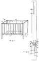
- a cot 1 having a drop side 2, wherein there is a mechanism 3 for raising and lowering the drop side 2 comprising complementary relatively slidable means 4, 5 on opposite ends of the drop side 2 and adjacent members 6 of the cot, and biassing means 7 adapted to secure the drop side 2 in the raised position and which allows the drop side 2 to move to the lowered position when the bias thereof is overcome.
- the relatively slidable means 4, 5 comprises a groove 8 in the adjacent member 6 of the cot 1, for example the ends, and projecting spigots 4 with enlarged heads (not shown) projecting from the opposite ends of the drop side 2.
- the enlarged heads are spaced from the opposite ends of the drop side 2 a sufficient distance to engage in the respective grooves 8, and allow relative sliding motion vertically.
- the grooves 8 are of T-shape in cross section, the enlarged heads essentially engaging in and sliding up and down in the "head" 9 of the "T", the shank of the "T” allowing for passage and sliding of the spigot 4, which is of less lateral dimension then the head.
- the groove 8 has an enlarged part 10 at the bottom, as viewed, for initial entry of the head and there is mounted therein a resilient buffer (not shown).
- the upper (as viewed) end of the groove 8 leads to a seat in the form of a blind slot 11, the seat 11 being displaced laterally of the plane of the length of the main body of the groove 8 from which it is separated by an upstanding nib 12 having a rounded nose or free end.
- the biassing means 7 of the mechanism 3 is in the form of a spring inclined towards the blind slot 11 from a side of the groove 8 opposite the blind slot.
- the spring in the embodiment shown is in the form of a leaf spring 13, which is one leg of a V-shaped spring the other 14 of which terminates in a hook 15 which hooks over a fixing device such as a screw 16.
- the spring 7 is mounted in a pressing set in a rebate in the body of the end member of the cot and this is covered with a metal plate 17, also set in the rebate to be substantially flush with the face of the body facing the end of the drop side 2, and providing the nib 12.
- the screw 16 is one of four screws 16, 16', 16'', 16''' which hold the pressing and plate together and in position in the body of end member 6.
- the mechanism described is on a lower part of the face of the end member 6 of the cot. Above it there is a further groove 18 which receives a projecting spigot of the cot drop side 2, for relative sliding motion, there being a buffer (not shown) in an enlarged lower part 19 of the groove 18.
- the horizontal axis of the grooves 8 is laterally offset from, and subtantially parallel to, the longitudinal axis of the groove 18.
- the axis of the groove 18 is colinear with the centre of the slot 11.
- the spiogot 4 is seated in the seat 11 and is held there by the spring 13, which acts as a guard to prevent unwanted use.
- the drop side 2 is therefore safely and securely maintained in the raised position.
- To lower the drop side 2 it is gripped, raised and at the same time pushed by the leg or hip of the user outside the cot 1 towards the interior of the cot so that the spigot 4 pushes the spring 13 against its bias to the right as viewed so that the groove 8 becomes unobstracted; the side 2 can then be lowered, spigots 4 travelling down their respective grooves to rest on the buffers, which absorb any shocks on impact.
- the drop side can be manipulated with one hand in raising and lowering operations.
Landscapes
- Saccharide Compounds (AREA)
- Holders For Apparel And Elements Relating To Apparel (AREA)
- Slide Fasteners, Snap Fasteners, And Hook Fasteners (AREA)
- Cultivation Receptacles Or Flower-Pots, Or Pots For Seedlings (AREA)
- Organic Low-Molecular-Weight Compounds And Preparation Thereof (AREA)
- Nitrogen Condensed Heterocyclic Rings (AREA)
- Dry Shavers And Clippers (AREA)
- Mechanical Treatment Of Semiconductor (AREA)
Claims (9)
- Kinderbett (1) mit einer anhebbaren und absenkbaren Absenkseite (2), umfassend gegenüberliegende Enden der Absenkseite (2) sowie benachbarte Elemente des Kinderbetts (1), eine Nut (8) in jede der benachbarten Elemente und vorspringende Zapfen an den gegenüberliegenden Enden der Absenkseite (2) und eine Einrichtung, die dazu ausgelegt ist, die Absenkseite (2) in der angehobenen Position festzusetzen und die es zuläßt, daß sich die Absenkseite (2) in die abgesenkte Position bewegt,
dadurch gekennzeichnet,
daß die Nut (8) in einem Blindschlitz (11) in einer Ebene endet, die im wesentlichen parallel zu der Ebene der Länge der Nut (8) liegt, und daß die Einrichtung ein Vorspannmittel (7) umfaßt, das normalerweise den Durchgang zwischen dem Blindschlitz (11) und der Nut (8) versperrt, wobei die Vorspannung des Mittels (7) durch eine Anhebebewegung und seitliche Bewegung der Absenkseite (2) überwunden wird. - Kinderbett nach Anspruch 1,
dadurch gekennzeichnet,
daß der Blindschlitz (11) durch eine nach oben stehende Nase (12) von der Nut (8) getrennt ist. - Kinderbett nach Anspruch 2,
dadurch gekennzeichnet,
daß die Vorspanneinrichtung (7) eine Feder (13) umfaßt, die zum Blindschlitz (11) hin geneigt ist. - Kinderbett nach Anspruch 3,
dadurch gekennzeichnet,
daß die Feder (13) eine Blattfeder ist, die um etwa 30° zur Länge der Nut (8) geneigt ist. - Kinderbett nach Anspruch 4,
dadurch gekennzeichnet,
daß die Feder (13) im wesentlichen eine V-Gestalt hat, und daß ein Bein (14) der Feder in einem Haken (15) endet, der an einer Befestigungsvorrichtung (16) befestigt ist. - Kinderbett nach einem der vorangehenden Ansprüche,
gekennzeichnet durch
eine weitere Nut (18), die im Gebrauch oberhalb der Nut (8) von dieser beabstandet angeordnet ist, und durch einen Zapfen, der in der Nut (18) aufgenommen ist. - Kinderbett nach Anspruch 6,
dadurch gekennzeichnet,
daß die Längsachse der Nut (8) seitlich zu der Längsachse der Nut (18) versetzt ist und im wesentlichen parallel zu dieser Achse verläuft. - Kinderbett nach einem der Ansprüche 6 oder 7,
gekennzeichnet durch
einen vergrößerten im Gebrauch unteren Bereich (10, 19), der jeweiligen Nut (8, 18). - Kinderbett nach Anspruch 8,
dadurch gekennzeichnet,
daß die vergrößerten Bereiche (10, 19) jeweils einen Puffer enthalten.
Priority Applications (1)
| Application Number | Priority Date | Filing Date | Title |
|---|---|---|---|
| AT9191306913T ATE105160T1 (de) | 1990-08-21 | 1991-07-29 | Kinderbett. |
Applications Claiming Priority (2)
| Application Number | Priority Date | Filing Date | Title |
|---|---|---|---|
| GB9018305 | 1990-08-21 | ||
| GB909018305A GB9018305D0 (en) | 1990-08-21 | 1990-08-21 | A cot |
Publications (2)
| Publication Number | Publication Date |
|---|---|
| EP0472302A1 EP0472302A1 (de) | 1992-02-26 |
| EP0472302B1 true EP0472302B1 (de) | 1994-05-04 |
Family
ID=10680977
Family Applications (1)
| Application Number | Title | Priority Date | Filing Date |
|---|---|---|---|
| EP91306913A Expired - Lifetime EP0472302B1 (de) | 1990-08-21 | 1991-07-29 | Kinderbett |
Country Status (4)
| Country | Link |
|---|---|
| EP (1) | EP0472302B1 (de) |
| AT (1) | ATE105160T1 (de) |
| DE (1) | DE69101890D1 (de) |
| GB (1) | GB9018305D0 (de) |
Families Citing this family (4)
| Publication number | Priority date | Publication date | Assignee | Title |
|---|---|---|---|---|
| AU702126B2 (en) * | 1995-12-07 | 1999-02-11 | Joyce, Janette Lois | Improvements in cots |
| ITBS20020100U1 (it) * | 2002-09-11 | 2004-03-12 | Foppa Pedretti Spa | Sistema di bloccaggio della sponda di lettini per bambini |
| RU2304419C2 (ru) * | 2005-08-04 | 2007-08-20 | Семен Матвеевич Гандылян | Детская кровать с трансформируемой боковой стороной |
| CN101766413A (zh) * | 2010-01-25 | 2010-07-07 | 汤克引 | 婴儿床 |
Family Cites Families (2)
| Publication number | Priority date | Publication date | Assignee | Title |
|---|---|---|---|---|
| GB102775A (en) * | 1916-04-10 | 1916-12-28 | Gavin Ralston Craig | Improvements in and relating to Cots and the like. |
| GB419613A (en) * | 1933-05-27 | 1934-11-15 | Arthur Alexander Gooch | Improvements in child's cots |
-
1990
- 1990-08-21 GB GB909018305A patent/GB9018305D0/en active Pending
-
1991
- 1991-07-29 DE DE69101890T patent/DE69101890D1/de not_active Expired - Lifetime
- 1991-07-29 EP EP91306913A patent/EP0472302B1/de not_active Expired - Lifetime
- 1991-07-29 AT AT9191306913T patent/ATE105160T1/de not_active IP Right Cessation
Also Published As
| Publication number | Publication date |
|---|---|
| DE69101890D1 (de) | 1994-06-09 |
| ATE105160T1 (de) | 1994-05-15 |
| EP0472302A1 (de) | 1992-02-26 |
| GB9018305D0 (en) | 1990-10-03 |
Similar Documents
| Publication | Publication Date | Title |
|---|---|---|
| GB2192358A (en) | Knife | |
| US4170042A (en) | Readily releasable powered visor-and-lock assembly for helmet | |
| US12194899B2 (en) | Child restraint system and adjustable headrest assembly thereof | |
| US4909574A (en) | Child's car seat restraint system | |
| US6658678B2 (en) | Attaching articles to bed railings | |
| WO1990002504A1 (en) | An arrangement in connection with an adjustable back rest cushion of a chair | |
| IT1301808B1 (it) | Casco di sicurezza con dispositivo per il bloccaggio e lo sbloccaggiodi parti mobili | |
| US20150321639A1 (en) | Anchorage Device | |
| US5004253A (en) | Guard attachment/removal structure in baby carriage | |
| EP0472302A1 (de) | Kinderbett | |
| US6796757B1 (en) | Ambulance cot lock | |
| US3390436A (en) | Releasable belt retainer apparatus for safety belt buckles | |
| CA2302066C (en) | Child's crib | |
| DE3863087D1 (de) | Sperrvorrichtung fuer einen staubsauger. | |
| US3911510A (en) | Two motion safety lock for crib drop sides | |
| US3498000A (en) | Takeout apparatus for aluminum window sash | |
| JP3156562U (ja) | 巻尺用ベルトクリップ | |
| EP1328231B1 (de) | Haltevorrichtung für eine transportliege | |
| US3862455A (en) | Double action safety lock for crib sides | |
| US6505360B2 (en) | Crib with drop side, and guiding and locking mechanism therefor | |
| US6244634B1 (en) | Apparatus for actuating the retaining locks of a cassette | |
| CN218009065U (zh) | 滑动杆组件、侧护栏以及婴儿床 | |
| KR100755904B1 (ko) | 슬라이드식 도어의 안전장치 | |
| DE3688626D1 (de) | Feststellvorrichtung fuer einen fenster- oder tuerfluegel in wenigstens einer spaltlueftungsstellung. | |
| JP3021148U (ja) | 乳母車の握り手棒前後進制御装置 |
Legal Events
| Date | Code | Title | Description |
|---|---|---|---|
| PUAI | Public reference made under article 153(3) epc to a published international application that has entered the european phase |
Free format text: ORIGINAL CODE: 0009012 |
|
| AK | Designated contracting states |
Kind code of ref document: A1 Designated state(s): AT BE CH DE DK ES FR GB GR IT LI LU NL SE |
|
| 17P | Request for examination filed |
Effective date: 19920206 |
|
| 17Q | First examination report despatched |
Effective date: 19921204 |
|
| RAP1 | Party data changed (applicant data changed or rights of an application transferred) |
Owner name: MACLAREN LIMITED |
|
| GRAA | (expected) grant |
Free format text: ORIGINAL CODE: 0009210 |
|
| AK | Designated contracting states |
Kind code of ref document: B1 Designated state(s): AT BE CH DE DK ES FR GB GR IT LI LU NL SE |
|
| PG25 | Lapsed in a contracting state [announced via postgrant information from national office to epo] |
Ref country code: IT Free format text: LAPSE BECAUSE OF FAILURE TO SUBMIT A TRANSLATION OF THE DESCRIPTION OR TO PAY THE FEE WITHIN THE PRE;WARNING: LAPSES OF ITALIAN PATENTS WITH EFFECTIVE DATE BEFORE 2007 MAY HAVE OCCURRED AT ANY TIME BEFORE 2007. THE CORRECT EFFECTIVE DATE MAY BE DIFFERENT FROM THE ONE RECORDED.SCRIBED TIME-LIMIT Effective date: 19940504 Ref country code: GR Free format text: LAPSE BECAUSE OF FAILURE TO SUBMIT A TRANSLATION OF THE DESCRIPTION OR TO PAY THE FEE WITHIN THE PRESCRIBED TIME-LIMIT Effective date: 19940504 Ref country code: DE Effective date: 19940504 Ref country code: ES Free format text: THE PATENT HAS BEEN ANNULLED BY A DECISION OF A NATIONAL AUTHORITY Effective date: 19940504 Ref country code: NL Effective date: 19940504 Ref country code: SE Free format text: THE PATENT HAS BEEN ANNULLED BY A DECISION OF A NATIONAL AUTHORITY Effective date: 19940504 Ref country code: LI Effective date: 19940504 Ref country code: DK Effective date: 19940504 Ref country code: AT Effective date: 19940504 Ref country code: FR Effective date: 19940504 Ref country code: BE Effective date: 19940504 Ref country code: CH Effective date: 19940504 |
|
| REF | Corresponds to: |
Ref document number: 105160 Country of ref document: AT Date of ref document: 19940515 Kind code of ref document: T |
|
| REF | Corresponds to: |
Ref document number: 69101890 Country of ref document: DE Date of ref document: 19940609 |
|
| PG25 | Lapsed in a contracting state [announced via postgrant information from national office to epo] |
Ref country code: LU Free format text: LAPSE BECAUSE OF NON-PAYMENT OF DUE FEES Effective date: 19940731 |
|
| REG | Reference to a national code |
Ref country code: CH Ref legal event code: PL |
|
| EN | Fr: translation not filed | ||
| NLV1 | Nl: lapsed or annulled due to failure to fulfill the requirements of art. 29p and 29m of the patents act | ||
| PLBE | No opposition filed within time limit |
Free format text: ORIGINAL CODE: 0009261 |
|
| STAA | Information on the status of an ep patent application or granted ep patent |
Free format text: STATUS: NO OPPOSITION FILED WITHIN TIME LIMIT |
|
| 26N | No opposition filed | ||
| PGFP | Annual fee paid to national office [announced via postgrant information from national office to epo] |
Ref country code: GB Payment date: 19950616 Year of fee payment: 5 |
|
| PG25 | Lapsed in a contracting state [announced via postgrant information from national office to epo] |
Ref country code: GB Effective date: 19960729 |
|
| GBPC | Gb: european patent ceased through non-payment of renewal fee |
Effective date: 19960729 |