EP0472314A1 - Verfahren und Vorrichtung zur Abgrabung des Meeresbodens - Google Patents
Verfahren und Vorrichtung zur Abgrabung des Meeresbodens Download PDFInfo
- Publication number
- EP0472314A1 EP0472314A1 EP91307112A EP91307112A EP0472314A1 EP 0472314 A1 EP0472314 A1 EP 0472314A1 EP 91307112 A EP91307112 A EP 91307112A EP 91307112 A EP91307112 A EP 91307112A EP 0472314 A1 EP0472314 A1 EP 0472314A1
- Authority
- EP
- European Patent Office
- Prior art keywords
- nozzle
- axis
- effect
- jet
- nozzles
- Prior art date
- Legal status (The legal status is an assumption and is not a legal conclusion. Google has not performed a legal analysis and makes no representation as to the accuracy of the status listed.)
- Granted
Links
- 238000009412 basement excavation Methods 0.000 title claims abstract description 7
- 238000000034 method Methods 0.000 title claims description 15
- 230000000694 effects Effects 0.000 claims abstract description 34
- XLYOFNOQVPJJNP-UHFFFAOYSA-N water Substances O XLYOFNOQVPJJNP-UHFFFAOYSA-N 0.000 claims abstract description 23
- 238000005553 drilling Methods 0.000 claims description 4
- 239000004927 clay Substances 0.000 abstract description 6
- 238000012986 modification Methods 0.000 description 4
- 230000004048 modification Effects 0.000 description 4
- 238000002955 isolation Methods 0.000 description 2
- 239000012530 fluid Substances 0.000 description 1
- 230000002093 peripheral effect Effects 0.000 description 1
Images


Classifications
-
- E—FIXED CONSTRUCTIONS
- E02—HYDRAULIC ENGINEERING; FOUNDATIONS; SOIL SHIFTING
- E02F—DREDGING; SOIL-SHIFTING
- E02F3/00—Dredgers; Soil-shifting machines
- E02F3/04—Dredgers; Soil-shifting machines mechanically-driven
- E02F3/88—Dredgers; Soil-shifting machines mechanically-driven with arrangements acting by a sucking or forcing effect, e.g. suction dredgers
- E02F3/90—Component parts, e.g. arrangement or adaptation of pumps
- E02F3/92—Digging elements, e.g. suction heads
- E02F3/9243—Passive suction heads with no mechanical cutting means
- E02F3/925—Passive suction heads with no mechanical cutting means with jets
-
- E—FIXED CONSTRUCTIONS
- E02—HYDRAULIC ENGINEERING; FOUNDATIONS; SOIL SHIFTING
- E02F—DREDGING; SOIL-SHIFTING
- E02F5/00—Dredgers or soil-shifting machines for special purposes
- E02F5/003—Dredgers or soil-shifting machines for special purposes for uncovering conduits
Definitions
- the invention relates to methods of performing seabed excavation and to a tool for performing the method.
- the method is particularly suitable, for example, for excavating the seabed beneath a frame to enable isolation valves to be installed or in a coffer dam in order to expose a buried pipeline.
- the seabed is more or less horizontal.
- the method has other applications including those in which the seabed in non-horizontal, so that the array of water jet nozzles has to be operated in a plane other than horizontal. For that reason, the term 'depth of cutting' as used herein is not to be limited to a vertical direction.
- a method of performing seabed excavation comprises rotating an array of a minimum of three water nozzles about a axis of rotation and moving said axis parallel to itself in at least one direction, the effect of the jet from a first nozzle which lies nearer to said axis intersecting at a first depth of cutting the effect of the jet from a second nozzle, which lies further from the axis, the third nozzle being further from said axis than said first nozzle and the effect of its jet intersecting at a second depth of cutting less than said first depth, the effect of the jet from said first nozzle, and removing debris from the result of action of said jets.
- a tool for performing the method comprises a rotatably assembly comprising a generally planar member supported by a hub, the plane of the member being at right angles to the rotational axis of the rotatable assembly and the hub forming an inlet for debris, the tool being movable parallel to the said axis in at least one direction, and an array of a minimum of three water nozzles mounted on said planar member, the effect of the jet from a first nozzle which lies nearer to said axis intersecting the effect of the jet from a second nozzle, which lies further said axis, at a first depth of cutting, the third nozzle being further from said axis than said first nozzle and the effect of its jet intersecting the effect of the jet from the first nozzle at a second depth of cutting less than said first depth, and a jet pump in a conduit for removing debris through said inlet from the result of action of said jets.
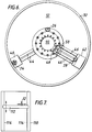
- Figures 1-3 show modes of operation of the tool 10 shown in Figures 4-6.
- the tool 10 consists of an array of three nozzles mounted on a circular disc 12.
- the disc 12 is rotatable about an axis 14 normal to the disc 12.
- the tool 10 is movable from right to left as shown in the Figures (and back from left to right).
- the tool 10 is also movable in both directions transversely to the plane of the Figures and can also move up and down in the plane of the Figures as shown.
- Each nozzle emits a jet of high pressure (eg 3000 pounds per square inch) water and the effects of these jets are shown by three lines 16, 17, 18 in the figures.
- the tool 10 is designed to cut and excavate a seabed consisting of clay, for example the boulder clay encountered in the Morecambe Bay zone of the North Sea. Such excavation is required to enable buried pipelines to be exposed, for example, within a coffer dam.
- Figure 1 shows the mode of operation when the tool 10 advances at a constant height above the seabed 20.
- a shallow trench 22 is cut out.
- the sides of the trench are vertical owing to the effect 16, together with the effect 17, which enables the segment of clay to be detached.
- the nozzle producing the effect 16 is angled very slightly to point outside the periphery of the disc 12 as described below.
- the sides of the trench would be sloping, at the angle of the effect 18.
- the forward motion of the disc 12 would repeatedly strip off sections of clay at that angle thus producing the trench 22.
- Figure 2 shows an intermediate stage.
- the disc 12 can thus cut clay right up to a vertical boundary in any plane. Further progress in cutting, now at the new depth of cutting shown in Figure 3, can be made by advancing the disc 12 from left to right back along the route of the trench 22, if desired. Of course, the whole of an area (for example the rectangular area within a coffer dam) can be cut at the depth of cutting shown in Figure 1 before any sinking of the disc 12 is attempted. Then, a new first trench is cut from the position shown in Figure 3 and, using cuts at the same depth, the whole area is again cut. Thus, progressively, the whole area may be excavated to any depth.
- an area for example the rectangular area within a coffer dam
- Figure 4 shows the three nozzles 24, 26, 28 producing the effects 16, 17, 18 just referred to.
- the nozzles 24, 26 28 form an array mounted on the disc 12 supported by a hub 30, part of which is shown in Figure 4 but which is ;better shown in Figure 5.
- the disc 12 has a downwardly extending peripheral circular flange 32.
- the angle of inclination of the nozzle 24 produces an effect 16 which intersects with the effect 17 from the nozzle 26 at a point close to or on the notional cylinder, the continuation downwardly of the flange 32. This means the effect 16 excavates a vertical wall which just clear the flange 32.
- Figures 1 to 4 shown the lines 16-18 or the three nozzles 24, 26 and 28 in an idealised manner, all lying in the same vertical plane.
- the three nozzles are distributed about the centre of the disc 12 ad 120 degree spacing, as shown in Figure 6.
- Each nozzle 24, 28 is mounted in its own manifold 40, 42, respectively, and is fed by tubes 44, 46, respectively, from a water distribution annulus 48 ( Figure 5).
- the nozzle 26 is mounted on the hub 30 and communicates directly with the water distribution annulus 48 ( Figure 4).
- the effect of rotation of the disc 12 makes the effects of the nozzles as explained with respect to Figures 1 to 4.
- the water distribution annulus 48 is fed by a plurality of drillings 50 which extend longitudinally within the wall of the hub 30, which with the disc 12 forms the rotatable assembly 51 of the tool.
- the drillings 50 are fed from a water feed annulus 52 machined in the non-rotatable assembly 54.
- High pressure water seals 56, 58 are positioned in the non-rotatably assembly 54 on each side of the water feed annulus 52.
- the water reaches the feed annulus 52 through three cross-drillings 60 in the non-rotatable assembly 54, three water transfer tubes 62 and three hoses 64 extending downwardly within a tubular mast 66.
- the water fed to the nozzles 24, 26, 28 is supplied from a point remote from the vicinity of cutting effected by the nozzles 24, 26, 28.
- the hub 30 is rotatably mounted in two sets of ball bearings 68, 70 and carried a gear 72 which meshes with another gear 74 driven by a hydraulic motor 76.
- a brush seal 78 engages the upper end of the hub 30.
- a lip seal 80 engages the hub 30 beneath the high pressure seals 56, 58.
- a lip seal 82 and a brush seal 84 are also provided.
- Debris is removed from the seabed, resulting from the effcts of the jets 16, 17, 18 upwards through the inlet 90 formed by the bore of the hub 30.
- the entrance to the inlet has a coarse mesh grid 92 placed over it.
- Upflow through the inlet 90 is produced by a jet pump located at 94 and the debris is ejected through a conduit 94 leading to a remote point of disposal. Water flow hoses for the jet pump are connected at 96.
- a supply of hydraulic fluid (and a return path not shown) for the hydraulic motor 76 is fed by a hose through the centre of the mast 66 to the bulkhead connector 100. From there another hose connects with the motor 76.
- the tool is part of an arrangement for excavating the seabed within a coffer dam 110 (Figure 7).
- the apparatus shown in Figure 5 includes the lower end of a mast 66 which is mounted on a gantry 112 movable along the coffer dam 110 on a pair of rails 114.
- the mast 66 is mounted so as to be traversable along the gantry 112 and also so as to be movable towards and away from the seabed.
- the seabed is considered to be horizontal
- the array of nozzles 24, 26 and 28 may be operated in a plane which is other than horizontal, for example where a sloping seabed is being excavated or where a vertical wall is to be excavated.
- the depth of cutting is not limited to a vertical direction, for that reason.
- Further nozzles can be used in modifications. For example, further nozzles on the same pitch circle as the nozzle 28 can be used. This will have the effect of deepening the trench 22 but reducing the rate of advance. Further nozzles corresponding to the nozzles 24 and 26 can be used but in all cases more water power must be provided or else, or in addition, some control of the period during which the nozzles are 'on' will be needed.
- the mast 66 described above may, in a modification, be mounted on a frame instead of being mounted in a coffer dam. Such an arrangement is suitable for digging foundations for sub-sea isolation valves.
- the mast would be movable along the frame and also movable across the frame as well as being movable vertically.
- the tool may be mounted on a tracked sub-sea vehicle.
- the vehicle may have a plunge arm on which the tool is mounted.
- the tool can be remotely operable from a surface vessel or platform.
Landscapes
- Engineering & Computer Science (AREA)
- Mechanical Engineering (AREA)
- Mining & Mineral Resources (AREA)
- Civil Engineering (AREA)
- General Engineering & Computer Science (AREA)
- Structural Engineering (AREA)
- Earth Drilling (AREA)
- Drilling And Exploitation, And Mining Machines And Methods (AREA)
- Excavating Of Shafts Or Tunnels (AREA)
Applications Claiming Priority (2)
| Application Number | Priority Date | Filing Date | Title |
|---|---|---|---|
| GB9018257A GB2247261A (en) | 1990-08-20 | 1990-08-20 | Method and tool for seabed excavation |
| GB9018257 | 1990-08-20 |
Publications (2)
| Publication Number | Publication Date |
|---|---|
| EP0472314A1 true EP0472314A1 (de) | 1992-02-26 |
| EP0472314B1 EP0472314B1 (de) | 1994-12-28 |
Family
ID=10680948
Family Applications (1)
| Application Number | Title | Priority Date | Filing Date |
|---|---|---|---|
| EP91307112A Expired - Lifetime EP0472314B1 (de) | 1990-08-20 | 1991-08-02 | Verfahren und Vorrichtung zur Abgrabung des Meeresbodens |
Country Status (9)
| Country | Link |
|---|---|
| US (1) | US5155928A (de) |
| EP (1) | EP0472314B1 (de) |
| AU (1) | AU620761B1 (de) |
| CA (1) | CA2049484C (de) |
| DE (1) | DE69106275T2 (de) |
| DK (1) | DK0472314T3 (de) |
| ES (1) | ES2066362T3 (de) |
| GB (1) | GB2247261A (de) |
| NO (1) | NO302836B1 (de) |
Cited By (4)
| Publication number | Priority date | Publication date | Assignee | Title |
|---|---|---|---|---|
| FR2736664A1 (fr) * | 1995-07-11 | 1997-01-17 | Rivard Sa | Machine de terrassement ou de fouille a outil comportant des jets haute pression |
| FR2736665A1 (fr) * | 1995-07-11 | 1997-01-17 | Rivard Sa | Machine de terrassement ou de fouille a outil comportant des jets haute pression |
| WO1997048527A1 (en) * | 1996-06-21 | 1997-12-24 | Ilias Antonaros | Nozzles fitted on bar mechanism for treating steel surfaces |
| US6095721A (en) * | 1995-07-20 | 2000-08-01 | Geoteknisk Institut | Method and device for burying a conduit under water |
Families Citing this family (6)
| Publication number | Priority date | Publication date | Assignee | Title |
|---|---|---|---|---|
| NL9400551A (nl) * | 1994-04-07 | 1995-11-01 | Hollandsche Betongroep Nv | Werkwijze alsmede vaartuig voor het behandelen van een waterbodem. |
| GB2363407A (en) * | 2000-06-12 | 2001-12-19 | Frank Mohn Flatoey As | Trenching apparatus |
| US6817119B2 (en) * | 2002-01-24 | 2004-11-16 | William B. Kerfoot | Apparatus and methods for subsidence deepening |
| US9539149B2 (en) * | 2007-07-13 | 2017-01-10 | Ut-Battelle, Llc | Superhydrophobic, diatomaceous earth comprising bandages and method of making the same |
| CN104005731A (zh) * | 2014-06-13 | 2014-08-27 | 哈尔滨工程大学 | 海洋废弃设施排泥装置 |
| CN110566125A (zh) * | 2019-10-18 | 2019-12-13 | 成都睿智达科技有限公司 | 水切割喷嘴、水切割装置及其控制方法 |
Citations (1)
| Publication number | Priority date | Publication date | Assignee | Title |
|---|---|---|---|---|
| US2956354A (en) * | 1956-06-14 | 1960-10-18 | Charles W Varner | Dredging apparatus |
Family Cites Families (9)
| Publication number | Priority date | Publication date | Assignee | Title |
|---|---|---|---|---|
| US545762A (en) * | 1895-09-03 | Dredger | ||
| CH223897A (de) * | 1942-03-14 | 1942-10-31 | A D Sihl A G Vorm A Schmid Mas | Arbeitsgerät mit rotierenden Werkzeugen, insbesondere zur Verwendung beim Baggern, Bohren und Betonieren. |
| NL7408623A (en) * | 1974-06-26 | 1975-12-30 | Ihc Holland Nv | Suction dredger cutter head - has water jets aimed at area adjacent to where cutter is working |
| US4127950A (en) * | 1977-06-02 | 1978-12-05 | Brown & Root, Inc. | Bottom jetting device |
| NL7904177A (nl) * | 1979-05-28 | 1980-12-02 | Hollandsche Aanneming Bv | Werkwijze voor het baggeren van onder water gelegen grondmateriaal en een inrichting voor het uitvoeren van de werkwijze. |
| IT1138764B (it) * | 1981-05-04 | 1986-09-17 | Snam Progetti | Dispositivo per interramento o dissotterramento di condotte subacquee |
| DE3410981C1 (de) * | 1984-03-16 | 1985-05-09 | Charles Ingwiller Loegel jun. | Verfahren und Vorrichtung zum Schneiden von Gestein |
| JPS62111029A (ja) * | 1985-11-07 | 1987-05-22 | M Ii C Eng Service Kk | ポンプ式浚渫機 |
| SU1465526A1 (ru) * | 1987-04-23 | 1989-03-15 | Всесоюзный Научно-Исследовательский И Проектно-Конструкторский Институт По Осушению Месторождений Полезных Ископаемых, Специальным Горным Работам,Рудничной Геологии И Маркшейдерскому Делу | Устройство дл проходки траншей в грунте |
-
1990
- 1990-08-20 GB GB9018257A patent/GB2247261A/en not_active Withdrawn
-
1991
- 1991-08-02 DK DK91307112.2T patent/DK0472314T3/da active
- 1991-08-02 EP EP91307112A patent/EP0472314B1/de not_active Expired - Lifetime
- 1991-08-02 ES ES91307112T patent/ES2066362T3/es not_active Expired - Lifetime
- 1991-08-02 DE DE69106275T patent/DE69106275T2/de not_active Expired - Fee Related
- 1991-08-16 NO NO913208A patent/NO302836B1/no not_active IP Right Cessation
- 1991-08-19 CA CA002049484A patent/CA2049484C/en not_active Expired - Fee Related
- 1991-08-19 US US07/747,754 patent/US5155928A/en not_active Expired - Fee Related
- 1991-08-19 AU AU82572/91A patent/AU620761B1/en not_active Ceased
Patent Citations (1)
| Publication number | Priority date | Publication date | Assignee | Title |
|---|---|---|---|---|
| US2956354A (en) * | 1956-06-14 | 1960-10-18 | Charles W Varner | Dredging apparatus |
Non-Patent Citations (1)
| Title |
|---|
| PATENT ABSTRACTS OF JAPAN vol. 11, no. 330 (M-636)(2777) 28 October 1987 & JP-A-62 111 029 ( M II C ENG SERVICE K.K. ) 22 May 1987 * |
Cited By (4)
| Publication number | Priority date | Publication date | Assignee | Title |
|---|---|---|---|---|
| FR2736664A1 (fr) * | 1995-07-11 | 1997-01-17 | Rivard Sa | Machine de terrassement ou de fouille a outil comportant des jets haute pression |
| FR2736665A1 (fr) * | 1995-07-11 | 1997-01-17 | Rivard Sa | Machine de terrassement ou de fouille a outil comportant des jets haute pression |
| US6095721A (en) * | 1995-07-20 | 2000-08-01 | Geoteknisk Institut | Method and device for burying a conduit under water |
| WO1997048527A1 (en) * | 1996-06-21 | 1997-12-24 | Ilias Antonaros | Nozzles fitted on bar mechanism for treating steel surfaces |
Also Published As
| Publication number | Publication date |
|---|---|
| NO913208D0 (no) | 1991-08-16 |
| GB2247261A (en) | 1992-02-26 |
| DE69106275T2 (de) | 1995-05-18 |
| NO913208L (no) | 1992-02-21 |
| DK0472314T3 (da) | 1995-03-20 |
| GB9018257D0 (en) | 1990-10-03 |
| DE69106275D1 (de) | 1995-02-09 |
| CA2049484A1 (en) | 1992-02-21 |
| CA2049484C (en) | 1995-08-29 |
| EP0472314B1 (de) | 1994-12-28 |
| NO302836B1 (no) | 1998-04-27 |
| ES2066362T3 (es) | 1995-03-01 |
| AU620761B1 (en) | 1992-02-20 |
| US5155928A (en) | 1992-10-20 |
Similar Documents
| Publication | Publication Date | Title |
|---|---|---|
| EP2582885B1 (de) | Verfahren und vorrichtung für eine meeresboden-hilfsabsaugung | |
| US5155928A (en) | Method and tool for performing seabed excavation | |
| US5249378A (en) | Hydraulic thrust producing implement | |
| US6305879B1 (en) | Continuous ditch excavator | |
| US4225186A (en) | Horizontal mining machine and method of slot mining | |
| CN109594603B (zh) | 一种用于快速清理海管上方淤泥的射流型rov型挖沟机 | |
| US4409747A (en) | Digging apparatus | |
| US4470720A (en) | Underwater trenching & pipelaying apparatus | |
| CN114498456A (zh) | 一种绞喷式管缆铺埋机 | |
| RU2107776C1 (ru) | Способ выполнения подводных земляных работ с использованием дноуглубительного земснаряда и гидромониторное устройство для разработки траншей под водой, гидромониторный трубозаглубитель-траншеекопатель (варианты), трубозаглубитель-траншеекопатель (варианты) | |
| GB2423778A (en) | Laying of sub-sea cables, pipes and the like using a plough | |
| JPH06141430A (ja) | ウォータージェットドリル式掘削・布設・埋設装置 | |
| EP0521032B1 (de) | Verbesserungen an meeresbergbautechnik | |
| RU187634U1 (ru) | Универсальный траншейный проходчик | |
| JP2872498B2 (ja) | 浚渫装置 | |
| CN112575834A (zh) | 一种浅海水下自行走埋缆机 | |
| JP2798163B2 (ja) | 浚渫装置 | |
| JPH11123661A (ja) | アブレシブジェットによる切削方法及び装置 | |
| JPH0768863B2 (ja) | 小口径管路掘進用先導筒体とこれによる小口径管路掘進工法 | |
| JP2872500B2 (ja) | 浚渫装置 | |
| JP2872499B2 (ja) | 浚渫装置 | |
| GB2065751A (en) | Deep water extractor | |
| RU2144250C1 (ru) | Способ оптимизации подводного инструментария при осуществлении прокладки кабеля волс | |
| RU2061818C1 (ru) | Способ разработки подводных траншей и дноуглубления и устройство для его осуществления | |
| GB2631402A (en) | Device, apparatus, system and method for sediment plume suppression |
Legal Events
| Date | Code | Title | Description |
|---|---|---|---|
| PUAI | Public reference made under article 153(3) epc to a published international application that has entered the european phase |
Free format text: ORIGINAL CODE: 0009012 |
|
| AK | Designated contracting states |
Kind code of ref document: A1 Designated state(s): BE DE DK ES FR GB IT NL SE |
|
| 17P | Request for examination filed |
Effective date: 19920127 |
|
| 17Q | First examination report despatched |
Effective date: 19930423 |
|
| GRAA | (expected) grant |
Free format text: ORIGINAL CODE: 0009210 |
|
| AK | Designated contracting states |
Kind code of ref document: B1 Designated state(s): BE DE DK ES FR GB IT NL SE |
|
| ITF | It: translation for a ep patent filed | ||
| EAL | Se: european patent in force in sweden |
Ref document number: 91307112.2 |
|
| REF | Corresponds to: |
Ref document number: 69106275 Country of ref document: DE Date of ref document: 19950209 |
|
| REG | Reference to a national code |
Ref country code: ES Ref legal event code: FG2A Ref document number: 2066362 Country of ref document: ES Kind code of ref document: T3 |
|
| REG | Reference to a national code |
Ref country code: DK Ref legal event code: T3 |
|
| ET | Fr: translation filed | ||
| PLBE | No opposition filed within time limit |
Free format text: ORIGINAL CODE: 0009261 |
|
| STAA | Information on the status of an ep patent application or granted ep patent |
Free format text: STATUS: NO OPPOSITION FILED WITHIN TIME LIMIT |
|
| 26N | No opposition filed | ||
| PGFP | Annual fee paid to national office [announced via postgrant information from national office to epo] |
Ref country code: FR Payment date: 20010705 Year of fee payment: 11 |
|
| PGFP | Annual fee paid to national office [announced via postgrant information from national office to epo] |
Ref country code: DK Payment date: 20010710 Year of fee payment: 11 |
|
| PGFP | Annual fee paid to national office [announced via postgrant information from national office to epo] |
Ref country code: GB Payment date: 20010713 Year of fee payment: 11 |
|
| PGFP | Annual fee paid to national office [announced via postgrant information from national office to epo] |
Ref country code: SE Payment date: 20010716 Year of fee payment: 11 |
|
| PGFP | Annual fee paid to national office [announced via postgrant information from national office to epo] |
Ref country code: DE Payment date: 20010718 Year of fee payment: 11 |
|
| PGFP | Annual fee paid to national office [announced via postgrant information from national office to epo] |
Ref country code: NL Payment date: 20010719 Year of fee payment: 11 |
|
| PGFP | Annual fee paid to national office [announced via postgrant information from national office to epo] |
Ref country code: ES Payment date: 20010807 Year of fee payment: 11 |
|
| PGFP | Annual fee paid to national office [announced via postgrant information from national office to epo] |
Ref country code: BE Payment date: 20010809 Year of fee payment: 11 |
|
| REG | Reference to a national code |
Ref country code: GB Ref legal event code: IF02 |
|
| PG25 | Lapsed in a contracting state [announced via postgrant information from national office to epo] |
Ref country code: GB Free format text: LAPSE BECAUSE OF NON-PAYMENT OF DUE FEES Effective date: 20020802 |
|
| PG25 | Lapsed in a contracting state [announced via postgrant information from national office to epo] |
Ref country code: SE Free format text: LAPSE BECAUSE OF NON-PAYMENT OF DUE FEES Effective date: 20020803 Ref country code: ES Free format text: LAPSE BECAUSE OF NON-PAYMENT OF DUE FEES Effective date: 20020803 |
|
| PG25 | Lapsed in a contracting state [announced via postgrant information from national office to epo] |
Ref country code: BE Free format text: LAPSE BECAUSE OF NON-PAYMENT OF DUE FEES Effective date: 20020831 |
|
| PG25 | Lapsed in a contracting state [announced via postgrant information from national office to epo] |
Ref country code: DK Free format text: LAPSE BECAUSE OF NON-PAYMENT OF DUE FEES Effective date: 20020930 |
|
| BERE | Be: lapsed |
Owner name: *BG PUBLIC LIMITED COMPANY Effective date: 20020831 |
|
| PG25 | Lapsed in a contracting state [announced via postgrant information from national office to epo] |
Ref country code: NL Free format text: LAPSE BECAUSE OF NON-PAYMENT OF DUE FEES Effective date: 20030301 Ref country code: DE Free format text: LAPSE BECAUSE OF NON-PAYMENT OF DUE FEES Effective date: 20030301 |
|
| GBPC | Gb: european patent ceased through non-payment of renewal fee |
Effective date: 20020802 |
|
| REG | Reference to a national code |
Ref country code: DK Ref legal event code: EBP |
|
| EUG | Se: european patent has lapsed | ||
| PG25 | Lapsed in a contracting state [announced via postgrant information from national office to epo] |
Ref country code: FR Free format text: LAPSE BECAUSE OF NON-PAYMENT OF DUE FEES Effective date: 20030430 |
|
| NLV4 | Nl: lapsed or anulled due to non-payment of the annual fee |
Effective date: 20030301 |
|
| REG | Reference to a national code |
Ref country code: FR Ref legal event code: ST |
|
| REG | Reference to a national code |
Ref country code: ES Ref legal event code: FD2A Effective date: 20030912 |
|
| PG25 | Lapsed in a contracting state [announced via postgrant information from national office to epo] |
Ref country code: IT Free format text: LAPSE BECAUSE OF NON-PAYMENT OF DUE FEES;WARNING: LAPSES OF ITALIAN PATENTS WITH EFFECTIVE DATE BEFORE 2007 MAY HAVE OCCURRED AT ANY TIME BEFORE 2007. THE CORRECT EFFECTIVE DATE MAY BE DIFFERENT FROM THE ONE RECORDED. Effective date: 20050802 |