EP0472363B1 - Vorrichtung zur Bestimmung der Abweichung des Flüssigkeitsniveaus in einem Gefäss - Google Patents
Vorrichtung zur Bestimmung der Abweichung des Flüssigkeitsniveaus in einem Gefäss Download PDFInfo
- Publication number
- EP0472363B1 EP0472363B1 EP91307533A EP91307533A EP0472363B1 EP 0472363 B1 EP0472363 B1 EP 0472363B1 EP 91307533 A EP91307533 A EP 91307533A EP 91307533 A EP91307533 A EP 91307533A EP 0472363 B1 EP0472363 B1 EP 0472363B1
- Authority
- EP
- European Patent Office
- Prior art keywords
- vessel
- liquid
- tubular member
- volume
- level
- Prior art date
- Legal status (The legal status is an assumption and is not a legal conclusion. Google has not performed a legal analysis and makes no representation as to the accuracy of the status listed.)
- Expired - Lifetime
Links
- 239000007788 liquid Substances 0.000 title claims abstract description 41
- 238000003780 insertion Methods 0.000 claims abstract description 8
- 230000037431 insertion Effects 0.000 claims abstract description 8
- 239000012530 fluid Substances 0.000 claims abstract description 7
- 238000006073 displacement reaction Methods 0.000 claims description 14
- 239000000463 material Substances 0.000 claims description 6
- 238000005259 measurement Methods 0.000 claims description 2
- 230000003466 anti-cipated effect Effects 0.000 description 2
- 238000010276 construction Methods 0.000 description 2
- 239000007789 gas Substances 0.000 description 2
- 239000003915 liquefied petroleum gas Substances 0.000 description 2
- 238000000034 method Methods 0.000 description 2
- 239000008232 de-aerated water Substances 0.000 description 1
- 230000008020 evaporation Effects 0.000 description 1
- 238000001704 evaporation Methods 0.000 description 1
- 230000005484 gravity Effects 0.000 description 1
- 238000007726 management method Methods 0.000 description 1
- 229920000728 polyester Polymers 0.000 description 1
- 229920001225 polyester resin Polymers 0.000 description 1
- 239000004645 polyester resin Substances 0.000 description 1
- 230000000717 retained effect Effects 0.000 description 1
Images



Classifications
-
- G—PHYSICS
- G01—MEASURING; TESTING
- G01F—MEASURING VOLUME, VOLUME FLOW, MASS FLOW OR LIQUID LEVEL; METERING BY VOLUME
- G01F23/00—Indicating or measuring liquid level or level of fluent solid material, e.g. indicating in terms of volume or indicating by means of an alarm
- G01F23/04—Indicating or measuring liquid level or level of fluent solid material, e.g. indicating in terms of volume or indicating by means of an alarm by dip members, e.g. dip-sticks
-
- G—PHYSICS
- G01—MEASURING; TESTING
- G01F—MEASURING VOLUME, VOLUME FLOW, MASS FLOW OR LIQUID LEVEL; METERING BY VOLUME
- G01F19/00—Calibrated capacity measures for fluids or fluent solid material, e.g. measuring cups
-
- G—PHYSICS
- G01—MEASURING; TESTING
- G01F—MEASURING VOLUME, VOLUME FLOW, MASS FLOW OR LIQUID LEVEL; METERING BY VOLUME
- G01F25/00—Testing or calibration of apparatus for measuring volume, volume flow or liquid level or for metering by volume
- G01F25/0092—Testing or calibration of apparatus for measuring volume, volume flow or liquid level or for metering by volume for metering by volume
-
- F—MECHANICAL ENGINEERING; LIGHTING; HEATING; WEAPONS; BLASTING
- F02—COMBUSTION ENGINES; HOT-GAS OR COMBUSTION-PRODUCT ENGINE PLANTS
- F02B—INTERNAL-COMBUSTION PISTON ENGINES; COMBUSTION ENGINES IN GENERAL
- F02B3/00—Engines characterised by air compression and subsequent fuel addition
- F02B3/06—Engines characterised by air compression and subsequent fuel addition with compression ignition
Definitions
- the invention relates to an apparatus for determining the deviation in the level of liquid in a vessel from a desired level corresponding to a preset level. More particularly the invention relates to an apparatus for determining the accuracy of a volume of liquid dispensed via a dispenser such as a petrol, liquid gas or diesel pump dispenser.
- a dispenser such as a petrol, liquid gas or diesel pump dispenser.
- the object of the invention is to provide such an apparatus which is relatively simple in construction and operation but which has a high degree of accuracy in use.
- the displacement means comprises an elongate member which is inserted into the vessel to displace the level of liquid in the vessel upwardly over the weir means.
- the displacement means comprises a hollow tubular member which is closed at the lower end thereof.
- the tubular member has an inlet defining the weir means over which the displaced liquid flows on insertion of the tubular member.
- the inlet is located in the tubular member at a level corresponding to the desired level in the vessel.
- an indicating scale is provided in the tubular member.
- the scale is provided by an elongate scale member extending through the tubular member, the scale member being graduated to indicate the deviation in the volume dispensed from a preset volume.
- the apparatus includes a vessel for collecting dispensed liquid, the vessel having a narrowed neck portion in which the fluid is displaced by the displacement means.
- the vessel includes an enlarged filling portion above the neck portion.
- the vessel includes a base portion arid a conical portion between the base portion and the neck portion.
- the vessel includes volume adjusment means for calibrating the preset volume.
- the adjustment means comprises a body member in the vessel, the body member being movable into and out of the vessel to calibrate the test volume.
- the body is of flexible material.
- the weir means comprises an outlet in the vessel adjacent to the level corresponding to the preset volume, displaced liquid passing through the outlet for measurement to determine the deviation in the volume of liquid in the vessel from the preset volume.
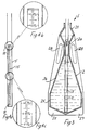
- An indicating scale is provided in the tubular member 5 by an inner closed tubular member 15 which is fixed in position relative the tube 5 and has marked thereon or provided therein scale lines indicating the deviation in the amount of fluid dispensed into the vessel 2 from the desired preset amount.
- the scale is marked to indicate the deviation from the desired amount either in direct volume terms such as millilitres or, as in the case illustrated, in percentage amounts to an accuracy of at least ⁇ 0.05%.
- the inlet hole 10 may be of any desired shape and configuration such as V-shape. Alternatively, two or more holes or a slot or slots may be provided.
- the vessel 2 may be of any desired shape and configuration.
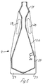
- the vessel includes a narrowed neck portion 20 in which the liquid is displaced by the tubular member 5 and an enlarged filling portion 21 above the neck 20 to avoid splash loss and to simulate the filling of a petrol or diesel tank of a motor vehicle.
- the vessel 2 below the neck portion 10 includes a generally tubular base portion 25 and a conical portion 26 leading from the base portion 25 to the narrowed neck portion 20.
- the vessel 2 is provided with base support legs 27 and carrying handles 28.
- the vessel is moulded from polyester resin-filled material to give substantially constant dimensions with the variations of temperature.
- the surface of the polyester material also has the surface tension which not only avoids air traps but also minimises adhesion on emptying of liquid from the vessel 2.
- the inlet hole 10 is almost circular, with a small downwardly extending extension.
- the extension may be of any suitable shape, preferably of V-shape. Alternatively, two or more holes or a slot or slots may be provided.
- the conical portion 26 of the vessel 2 ensures that air does not become trapped in the vessel 2.
- the narrowed neck portion 20 and the very small area defined between the tubular member 5 and the neck 10 on insertion of the tubular member 5 into the vessel 2 substantially eliminates errors that might arise due to the fact that the vessel 2 may not be supported on level ground.
- an amount is dispensed into the vessel 2 until the dispenser reads a known amount such as, for example, 10 litres.
- the vessel 2 used in this case will have a nominal volume of 10 litres and on filling by the dispenser the level of fluid in the vessel 2 will reach approximately to the lower part of the neck portion 20 of the vessel 2 as illustrated in Fig. 2.
- the tubular member 5 is then inserted into the vessel 2 until the lower closed end 11 hits the bottom of the vessel 2.
- Readings above and below that on the scale indicate to the user how accurate the pump is dispensing both below or above volume and the amount by which the volume is above or below the desired level.
- the dispensing pump may then be adjusted accordingly and the process repeated to check the accuracy of dispensing.
- the data collected using the apparatus of the invention may also be used in the calculation of stock errors and to assist in making volumetric and financial calculations useful in business management function of forecourt sites and the like.
- the scale By firstly restricting the upper level of liquid in the vessel 2, by secondly providing a very narrow gap between the displacement tube and the neck of the vessel 2 and by further elongating the amount of liquid in the tube by passing it into a narrowed space between the scale tube and the tubular member 5 a very high level of accuracy is achieved. Further, the scale is both quick and easy to read. Because the scale can be read quickly and easily, losses due to evaporation of volatile products are minimised.
- the adjustment means comprises a body 40, in this case of flexible material, mounted in the vessel 2, the body being movable into and out of the vessel 2 to calibrate the test volume.
- the flexible body 40 is of rubber or similar material and is moved into and out of the vessel 2 by means of a threaded bar 41 having a head 42 which is moulded into the flexible body 40.
- the threaded bar 41 is turned on a adjusting nut 43 to move the flexible body 40 inwardly and outwardly with respect to the vessel as required to raise or lower the liquid level in the vessel for calibration.
- the adjustment mechanism When set, the adjustment mechanism is covered and sealed by a cap 45.
- a cap 45 In the calibration procedure exactly 10 litres of de-aerated water is poured into the vessel 2 and the hollow tubular member 15 is inserted.
- the body 40 is moved into or out of the vessel 2 until a 0.00% reading is achieved on the scale tube 15. When this is achieved the body 40 is fixed in position as already described.
- the depth to which the tubular member 15 is inserted into the vessel 2 may be controlled manually or automatically, for example, taking account of temperature differences and/or the type of liquid being measured.
- Fig. 8 there is illustrated an apparatus according to another embodiment of the invention which is indicated generally by the reference numeral 50.
- the vessel 2 of the apparatus is similar to the vessel described above with reference to Figs. 1 to 7 and like parts are assigned the same reference numerals.
- the displacement means comprises an elongate member 51 and the vessel includes an overflow outlet 52 in the neck portion 20 thereof which defines a weir means for which liquid displaced on insertion of the member 51 is discharged through a tube 53 into a measuring phial such as a graduated cylinder 55.
- the apparatus 50 is operated in a similar manner to the apparatus described above with reference to Figs.
- the accuracy of the dispenser is determined by the amount of liquid which is delivered into the graduated cylinder 55 on insertion of the elongate rod 51. It will be appreciated that the measuring phial may be separate from, attached to or integral with the vessel 2.
- the displacement means of the invention may be used in association with vessels other than the types of vessels described. It is anticipated, for example, that the apparatus comprising the displacement means in the form of a tubular member 5 only may be used, in association with another vessel such as a volumetric flask, cylinder (graduated or otherwise), pressurised gas container, or where a known weight of liquid is dispensed into a vessel, and the volumetric deviation therefrom, is used as an accurate measure of specific gravity, or temperature.
- a volumetric flask cylinder (graduated or otherwise), pressurised gas container, or where a known weight of liquid is dispensed into a vessel, and the volumetric deviation therefrom, is used as an accurate measure of specific gravity, or temperature.
Landscapes
- Physics & Mathematics (AREA)
- Fluid Mechanics (AREA)
- General Physics & Mathematics (AREA)
- Loading And Unloading Of Fuel Tanks Or Ships (AREA)
- Measurement Of Levels Of Liquids Or Fluent Solid Materials (AREA)
- Automatic Analysis And Handling Materials Therefor (AREA)
- Centrifugal Separators (AREA)
- Level Indicators Using A Float (AREA)
- Containers And Packaging Bodies Having A Special Means To Remove Contents (AREA)
- Closures For Containers (AREA)
Claims (14)
- Vorrichtung (1) zum Bestimmen der Abweichung des Flüssigkeitsniveaus in einem Behälter (2) von einem gewünschten Niveau (3), welches einem vorgegebenen Volumen entspricht, wobei die Vorrichtung (1) als Wehr wirkende Mittel (10) und Verdrängungsmittel (5) umfassen, welche als Wehr wirkenden Mittel (10) einen Teil der Verdrängungsmittel (5) oder des Behälters (2) bilden, und welche Verdrängungsmittel (5) dafür ausgelegt sind, das Flüssigkeitsniveau im Behälter (2) über die als Wehr wirkenden Mittel (10) zu verschieben, und wobei die Vorrichtung weiter Mittel zur Sammlung von Flüssigkeit umfasst, welche mit einer Anzeigeskala versehen sind, mit deren Hilfe die verdrängte Flüssigkeit gemessen werden kann, um die Abweichung des Flüssigkeitsvolumens im Behälter (2) von dem vorgegebenen Volumen zu bestimmen.
- Vorrichtung nach Anspruch 1, wobei die Verdrängungsmittel ein längliches Teil (5) umfassen, welches in den Behälter (2) eingesetzt ist, um das Niveau der Flüssigkeit in dem Behälter (2) noch oben über die als Wehr wirkenden Mittel (10) zu verschieben.
- Vorrichtung nach Anspruch 2, wobei die Verdrängungsmittel ein hohles, röhrenförmiges Teil (5) umfassen, welches an seinem unteren Ende (11) geschlossen ist.
- Vorrichtung nach Anspruch 3, wobei das röhrenförmige Teil (5) einen Einlass (10) aufweist, welcher die als Wehr wirkenden Mittel bildet, über welches die verdrängte Flüssigkeit bei, Eintauchen des röhrenförmigen Teils (5) fliesst.
- Vorrichtung nach Anspruch 4, wobei der Einlass (10) an dem röhrenförmigen Teil (5) in einer Höhe angeordnet ist, welche dem gewünschten Niveau in dem Behälter (2) entspricht.
- Vorrichtung nach einem der Ansprüche 3 bis 5, wobei die Anzeigeskala (15) in dem röhrenförmigen Teil (5) vorgesehen ist.
- Vorrichtung nach Anspruch 6, wobei die Skala durch ein längliches Skalenteil (15) gebildet wird, welches sich durch das röhrenförmige Teil (5) erstreckt, und wobei das Skalenteil (15) mit einer Gradeinteilung versehen ist, um die Abweichung des abgegebenen Volumens vom vorgegebenen Volumen anzuzeigen.
- Vorrichtung nach einem der vorhergehenden Ansprüche, welche einen Behälter (2) zur Sammlung der abgegebenen Flüssigkeit einschliesst, der einen verengten Halsteil (20) hat, in welchen die Flüssigkeit durch die Verdrängungsmittel (5) hineinverdrängt wird.
- Vorrichtung nach Anspruch 8, wobei der Behälter (2) einen verbreiterten Einfüllteil (21) oberhalb des Halsteils (20) einschliesst.
- Vorrichtung nach einem der Ansprüche 8 oder 9, wobei der Behälter (2) einen Basisteil (25) und einen zwischen dem Basisteil (25) und dem Halsteil (20) angeordneten konischen Teil (26) einschliesst.
- Vorrichtung nach einem der Ansprüche 8 bis 10, wobei der Behälter (2) Mittel (40) zur Einstellung des Volumens für die Kalibrierung des vorgegebenen Volumens einschliesst.
- Vorrichtung nach Anspruch 11, wobei die Einstellmittel einen Körperteil (40) in dem Behälter (2) umfassen, welcher Körperteil (40) in den Behälter (2) hinein und aus dem Behälter (2) hinaus bewegbar ist, um das Testvolumen zu kalibrieren.
- Vorrichtung nach Anspruch 12, wobei der Körper (40) aus einem flexiblen Material ist.
- Vorrichtung nach einem der Ansprüche 8 bis 13, wobei das Wehr einen Auslass (52) in dem Behälter (2) in der Nähe des dem vorgegebenen Volumen entsprechenden Niveaus umfasst, und wobei für die Messung zur Bestimmung der Abweichung des Flüssigkeitsvolumens im Behälter (2) von dem vorgegebenen Volumen verdrängte Flüssigkeit durch den Auslass (52) fliesst.
Applications Claiming Priority (4)
| Application Number | Priority Date | Filing Date | Title |
|---|---|---|---|
| IE54690A IE77157B1 (en) | 1990-08-15 | 1990-08-15 | An apparatus for determining the deviation in the level of liquid in a vessel |
| IE54690 | 1990-08-15 | ||
| IE200691 | 1991-06-13 | ||
| IE200691 | 1991-06-13 |
Publications (3)
| Publication Number | Publication Date |
|---|---|
| EP0472363A2 EP0472363A2 (de) | 1992-02-26 |
| EP0472363A3 EP0472363A3 (en) | 1992-06-17 |
| EP0472363B1 true EP0472363B1 (de) | 1995-12-27 |
Family
ID=26318925
Family Applications (1)
| Application Number | Title | Priority Date | Filing Date |
|---|---|---|---|
| EP91307533A Expired - Lifetime EP0472363B1 (de) | 1990-08-15 | 1991-08-15 | Vorrichtung zur Bestimmung der Abweichung des Flüssigkeitsniveaus in einem Gefäss |
Country Status (9)
| Country | Link |
|---|---|
| US (1) | US5343732A (de) |
| EP (1) | EP0472363B1 (de) |
| JP (1) | JPH06341881A (de) |
| AT (1) | ATE132255T1 (de) |
| AU (1) | AU660281B2 (de) |
| CA (1) | CA2049268A1 (de) |
| DE (1) | DE69115795T2 (de) |
| ES (1) | ES2084114T3 (de) |
| IE (1) | IE77157B1 (de) |
Families Citing this family (6)
| Publication number | Priority date | Publication date | Assignee | Title |
|---|---|---|---|---|
| ES2147202T3 (es) * | 1992-07-31 | 2000-09-01 | Burgee Ltd | Aparato para la determinacion del volumen de un liquido. |
| EP0829709A1 (de) * | 1996-09-16 | 1998-03-18 | Raab Karcher Energy Services GmbH | Mobiles System zum Erfassen eines Heizwärmeverbrauchs von Heizkörpern gemäss dem Prinzip der Verdunstung |
| US6779399B2 (en) * | 2002-02-13 | 2004-08-24 | The United States Of America As Represented By The Secretary Of The Interior | Sprinkler performance evaluation catch cup including ground piercing support legs |
| RU2234686C2 (ru) * | 2002-07-08 | 2004-08-20 | Кожанов Анатолий Тимофеевич | Мерник для жидкости |
| US10006795B2 (en) | 2013-09-24 | 2018-06-26 | Pumpwatch Limited | Measuring vessel |
| CN116754038B (zh) * | 2023-05-31 | 2026-05-15 | 深圳普门科技股份有限公司 | 管路容积误差检验装置及方法 |
Family Cites Families (14)
| Publication number | Priority date | Publication date | Assignee | Title |
|---|---|---|---|---|
| US494467A (en) * | 1893-03-28 | Liquid measurer and extractor | ||
| US2236583A (en) * | 1940-03-13 | 1941-04-01 | Western Electric Co | Measuring device |
| US2971366A (en) * | 1957-09-27 | 1961-02-14 | Dearborn Gage Company | Gage calibration device |
| US3058353A (en) * | 1960-05-12 | 1962-10-16 | Robert C Irwin | Proportional liquid measuring device |
| US3521366A (en) * | 1969-07-28 | 1970-07-21 | Norton Co | Visual liquid level measuring device |
| GB1440185A (en) * | 1972-07-14 | 1976-06-23 | Smiths Industries Ltd | Medico-surgical liquid-measuring apparatus |
| US4062228A (en) * | 1974-04-12 | 1977-12-13 | Donald P. Matula | Powder moisture meter |
| GB1457457A (en) * | 1974-05-09 | 1976-12-01 | Philograph Publications | Liquid displacement measuring vessel particularly for educations use |
| US4033190A (en) * | 1976-02-09 | 1977-07-05 | Hudspeth Henry S | Precision measuring device |
| US4109530A (en) * | 1977-04-29 | 1978-08-29 | Steven M. Diamond | Specimen transfer container |
| US4531293A (en) * | 1984-02-03 | 1985-07-30 | Grinde James E | Gauge for indicating quantity of mixture components to be added to a tank |
| DE3431720A1 (de) * | 1984-06-06 | 1985-12-12 | Bernhard 7750 Konstanz Eisenhut | Messbecher fuer die dosierung von medien |
| US5125466A (en) * | 1986-03-18 | 1992-06-30 | Rhone-Poulenc Rorer Pharmaceuticals Inc. | Product-dispensing method and apparatus |
| US4928514A (en) * | 1987-09-15 | 1990-05-29 | Great Plains Industries, Inc. | Calibration container |
-
1990
- 1990-08-15 IE IE54690A patent/IE77157B1/en not_active IP Right Cessation
-
1991
- 1991-08-15 AT AT91307533T patent/ATE132255T1/de not_active IP Right Cessation
- 1991-08-15 AU AU82457/91A patent/AU660281B2/en not_active Ceased
- 1991-08-15 JP JP3205290A patent/JPH06341881A/ja active Pending
- 1991-08-15 US US07/745,080 patent/US5343732A/en not_active Expired - Fee Related
- 1991-08-15 EP EP91307533A patent/EP0472363B1/de not_active Expired - Lifetime
- 1991-08-15 ES ES91307533T patent/ES2084114T3/es not_active Expired - Lifetime
- 1991-08-15 CA CA002049268A patent/CA2049268A1/en not_active Abandoned
- 1991-08-15 DE DE69115795T patent/DE69115795T2/de not_active Expired - Fee Related
Also Published As
| Publication number | Publication date |
|---|---|
| DE69115795T2 (de) | 1996-09-19 |
| EP0472363A3 (en) | 1992-06-17 |
| AU660281B2 (en) | 1995-06-22 |
| US5343732A (en) | 1994-09-06 |
| ATE132255T1 (de) | 1996-01-15 |
| CA2049268A1 (en) | 1992-02-16 |
| EP0472363A2 (de) | 1992-02-26 |
| IE77157B1 (en) | 1997-12-03 |
| ES2084114T3 (es) | 1996-05-01 |
| AU8245791A (en) | 1992-02-20 |
| JPH06341881A (ja) | 1994-12-13 |
| DE69115795D1 (de) | 1996-02-08 |
Similar Documents
| Publication | Publication Date | Title |
|---|---|---|
| US5833124A (en) | Fluid dispensing device | |
| US7350418B2 (en) | Fluid supply assembly with measuring guide | |
| US4928514A (en) | Calibration container | |
| US5343732A (en) | Apparatus for determining the deviation in the level of liquid in a vessel | |
| AU613522B2 (en) | A device for measuring flow | |
| AU688267B2 (en) | Liquid volume measuring apparatus | |
| US4003499A (en) | Precision liquid dispensing device | |
| US5686704A (en) | Tare compensating tank weighing device | |
| US6494089B1 (en) | Rain gauge | |
| US1853813A (en) | Liquid measuring device | |
| WO2002059549A1 (en) | Container volume measuring device and method | |
| US10006795B2 (en) | Measuring vessel | |
| US624208A (en) | Liquid-dispensing apparatus | |
| GB2514413A (en) | A liquid level indicator device | |
| WO2001075404A1 (en) | Arm volume measurement | |
| US1861715A (en) | Liquid level indicating means | |
| US4422244A (en) | Elevation indicator | |
| US223999A (en) | Cheistophee g | |
| US103404A (en) | Improvement in apparatus for measuring liquids |
Legal Events
| Date | Code | Title | Description |
|---|---|---|---|
| PUAI | Public reference made under article 153(3) epc to a published international application that has entered the european phase |
Free format text: ORIGINAL CODE: 0009012 |
|
| AK | Designated contracting states |
Kind code of ref document: A2 Designated state(s): AT BE CH DE DK ES FR GB GR IT LI LU NL SE |
|
| PUAL | Search report despatched |
Free format text: ORIGINAL CODE: 0009013 |
|
| AK | Designated contracting states |
Kind code of ref document: A3 Designated state(s): AT BE CH DE DK ES FR GB GR IT LI LU NL SE |
|
| 17P | Request for examination filed |
Effective date: 19921217 |
|
| 17Q | First examination report despatched |
Effective date: 19940726 |
|
| RAP1 | Party data changed (applicant data changed or rights of an application transferred) |
Owner name: GLYNN, JAMES KEVIN |
|
| RIN1 | Information on inventor provided before grant (corrected) |
Inventor name: GLYNN, JAMES KEVIN |
|
| GRAA | (expected) grant |
Free format text: ORIGINAL CODE: 0009210 |
|
| AK | Designated contracting states |
Kind code of ref document: B1 Designated state(s): AT BE CH DE DK ES FR GB GR IT LI LU NL SE |
|
| PG25 | Lapsed in a contracting state [announced via postgrant information from national office to epo] |
Ref country code: IT Free format text: LAPSE BECAUSE OF FAILURE TO SUBMIT A TRANSLATION OF THE DESCRIPTION OR TO PAY THE FEE WITHIN THE PRE;WARNING: LAPSES OF ITALIAN PATENTS WITH EFFECTIVE DATE BEFORE 2007 MAY HAVE OCCURRED AT ANY TIME BEFORE 2007. THE CORRECT EFFECTIVE DATE MAY BE DIFFERENT FROM THE ONE RECORDED.SCRIBED TIME-LIMIT Effective date: 19951227 Ref country code: DK Effective date: 19951227 Ref country code: GR Free format text: LAPSE BECAUSE OF FAILURE TO SUBMIT A TRANSLATION OF THE DESCRIPTION OR TO PAY THE FEE WITHIN THE PRESCRIBED TIME-LIMIT Effective date: 19951227 Ref country code: NL Free format text: LAPSE BECAUSE OF FAILURE TO SUBMIT A TRANSLATION OF THE DESCRIPTION OR TO PAY THE FEE WITHIN THE PRESCRIBED TIME-LIMIT Effective date: 19951227 Ref country code: BE Effective date: 19951227 Ref country code: CH Effective date: 19951227 Ref country code: AT Effective date: 19951227 Ref country code: LI Effective date: 19951227 |
|
| REF | Corresponds to: |
Ref document number: 132255 Country of ref document: AT Date of ref document: 19960115 Kind code of ref document: T |
|
| REF | Corresponds to: |
Ref document number: 69115795 Country of ref document: DE Date of ref document: 19960208 |
|
| PG25 | Lapsed in a contracting state [announced via postgrant information from national office to epo] |
Ref country code: SE Effective date: 19960327 |
|
| ET | Fr: translation filed | ||
| REG | Reference to a national code |
Ref country code: ES Ref legal event code: FG2A Ref document number: 2084114 Country of ref document: ES Kind code of ref document: T3 |
|
| NLV1 | Nl: lapsed or annulled due to failure to fulfill the requirements of art. 29p and 29m of the patents act | ||
| PG25 | Lapsed in a contracting state [announced via postgrant information from national office to epo] |
Ref country code: LU Free format text: LAPSE BECAUSE OF NON-PAYMENT OF DUE FEES Effective date: 19960831 |
|
| PLBE | No opposition filed within time limit |
Free format text: ORIGINAL CODE: 0009261 |
|
| STAA | Information on the status of an ep patent application or granted ep patent |
Free format text: STATUS: NO OPPOSITION FILED WITHIN TIME LIMIT |
|
| 26N | No opposition filed | ||
| PGFP | Annual fee paid to national office [announced via postgrant information from national office to epo] |
Ref country code: GB Payment date: 20000214 Year of fee payment: 9 |
|
| PGFP | Annual fee paid to national office [announced via postgrant information from national office to epo] |
Ref country code: ES Payment date: 20000228 Year of fee payment: 9 Ref country code: FR Payment date: 20000228 Year of fee payment: 9 |
|
| PGFP | Annual fee paid to national office [announced via postgrant information from national office to epo] |
Ref country code: DE Payment date: 20000330 Year of fee payment: 9 |
|
| PG25 | Lapsed in a contracting state [announced via postgrant information from national office to epo] |
Ref country code: GB Free format text: LAPSE BECAUSE OF NON-PAYMENT OF DUE FEES Effective date: 20000815 |
|
| PG25 | Lapsed in a contracting state [announced via postgrant information from national office to epo] |
Ref country code: ES Free format text: LAPSE BECAUSE OF NON-PAYMENT OF DUE FEES Effective date: 20000816 |
|
| GBPC | Gb: european patent ceased through non-payment of renewal fee |
Effective date: 20000815 |
|
| PG25 | Lapsed in a contracting state [announced via postgrant information from national office to epo] |
Ref country code: FR Free format text: LAPSE BECAUSE OF NON-PAYMENT OF DUE FEES Effective date: 20010430 |
|
| PG25 | Lapsed in a contracting state [announced via postgrant information from national office to epo] |
Ref country code: DE Free format text: LAPSE BECAUSE OF NON-PAYMENT OF DUE FEES Effective date: 20010501 |
|
| REG | Reference to a national code |
Ref country code: FR Ref legal event code: ST |
|
| REG | Reference to a national code |
Ref country code: ES Ref legal event code: FD2A Effective date: 20010911 |
|
| REG | Reference to a national code |
Ref country code: CH Ref legal event code: PL Ref country code: CH Ref legal event code: EP |