EP0472393A2 - Streckmaschine - Google Patents
Streckmaschine Download PDFInfo
- Publication number
- EP0472393A2 EP0472393A2 EP91307629A EP91307629A EP0472393A2 EP 0472393 A2 EP0472393 A2 EP 0472393A2 EP 91307629 A EP91307629 A EP 91307629A EP 91307629 A EP91307629 A EP 91307629A EP 0472393 A2 EP0472393 A2 EP 0472393A2
- Authority
- EP
- European Patent Office
- Prior art keywords
- stretching
- stretching machine
- sheet
- hot
- air
- Prior art date
- Legal status (The legal status is an assumption and is not a legal conclusion. Google has not performed a legal analysis and makes no representation as to the accuracy of the status listed.)
- Granted
Links
Images




Classifications
-
- B—PERFORMING OPERATIONS; TRANSPORTING
- B29—WORKING OF PLASTICS; WORKING OF SUBSTANCES IN A PLASTIC STATE IN GENERAL
- B29C—SHAPING OR JOINING OF PLASTICS; SHAPING OF MATERIAL IN A PLASTIC STATE, NOT OTHERWISE PROVIDED FOR; AFTER-TREATMENT OF THE SHAPED PRODUCTS, e.g. REPAIRING
- B29C55/00—Shaping by stretching, e.g. drawing through a die; Apparatus therefor
- B29C55/02—Shaping by stretching, e.g. drawing through a die; Apparatus therefor of plates or sheets
- B29C55/10—Shaping by stretching, e.g. drawing through a die; Apparatus therefor of plates or sheets multiaxial
- B29C55/12—Shaping by stretching, e.g. drawing through a die; Apparatus therefor of plates or sheets multiaxial biaxial
- B29C55/16—Shaping by stretching, e.g. drawing through a die; Apparatus therefor of plates or sheets multiaxial biaxial simultaneously
- B29C55/165—Apparatus therefor
-
- B—PERFORMING OPERATIONS; TRANSPORTING
- B29—WORKING OF PLASTICS; WORKING OF SUBSTANCES IN A PLASTIC STATE IN GENERAL
- B29C—SHAPING OR JOINING OF PLASTICS; SHAPING OF MATERIAL IN A PLASTIC STATE, NOT OTHERWISE PROVIDED FOR; AFTER-TREATMENT OF THE SHAPED PRODUCTS, e.g. REPAIRING
- B29C55/00—Shaping by stretching, e.g. drawing through a die; Apparatus therefor
- B29C55/02—Shaping by stretching, e.g. drawing through a die; Apparatus therefor of plates or sheets
- B29C55/04—Shaping by stretching, e.g. drawing through a die; Apparatus therefor of plates or sheets uniaxial, e.g. oblique
- B29C55/08—Shaping by stretching, e.g. drawing through a die; Apparatus therefor of plates or sheets uniaxial, e.g. oblique transverse to the direction of feed
Definitions
- the present invention relates a stretching machine for stretching a stretchable long sheet-like member such as a polyethylene film (including a slitted film), a net, woven fabric and non-woven fabric, in the direction of width.
- a stretchable long sheet-like member such as a polyethylene film (including a slitted film), a net, woven fabric and non-woven fabric, in the direction of width.
- One end of the support plate is connected to a spline shaft at the inlet side for the sheet-like member, the other end at the outlet side rotating around the one end connected to the spline shaft, the one end being movable in a lateral direction.
- both the support plates accesibly connected with spline shafts make spreading size of sheet-like member adjustable, but stationary far infrared heater and nozzle make it impossible to heat all the stretched portions of the sheet-like member to uniform temperature.
- a stretching machine comprising a housing; a pair of frames which face each other within the housing; a pair of stretching pulleys each mounted to the frame; a belt which is wound around said stretching pulleys, a stretchable long sheet-like member being held between said stretching pulley and the belt which is wound around the pulley; hot-air generating means for generating air flow, heating it to hot air and blowing hot air against the sheet-like member; and hot-air circulating passages for circulating hot air which is blown against the sheet-like member.
- hot air is blown against the sheet-like member or film and circulates, thereby applying hot air again after heating to the sheet-like member and increasing thermal efficiency.
- all the sheet-like member is equally heated to uniform temperature to obtain a product having stable in quality.
- a stretching machine comprising transfer means for transferring a long sheet-like member which is held thereby, thereby spreading it in the direction of width of the sheet-like member; heating means for heating the sheet-like member during transfer on the transfer means; and cooling means for cooling the transfer means.
- the present invention prevents the sheet-like member from forming crease and cracks and from heat degradation.
- a stretching machine comprising a housing; a pair of holding transfer means for holding and transferring a stretchable long sheet-like member to spread it in the direction of width of the sheet-like member; inlet-side distance changing means for moving at least one of the holding transfer means at an inlet side for the sheet-like member in the direction of width of the sheet-like member, thereby changing the distance between said pair of holding transfer means at the inlet side; and outlet-side distance changing means for moving at least one of the holding transfer means at an outlet side for the sheet-like member in the direction of width of the sheet-like member, thereby changing the distance between said pair of holding transfer means at the outlet side.
- the distance between the support plates at the inlet or outlet side is independently variable, thereby changing stretch width or stretch ratio of the sheet-like member or film without interrupting the operation of the machine.
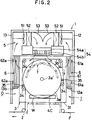
- the numeral 1 denotes a housing in a hot-air circulating stretching machine
- 2 denotes a base fixed to the bottom of the housing 1
- the numerals 3 and 3 denote a pair of support plates between which a distance is smaller at an inlet side "I” of a stretchable long sheet-like member or a film “F” and is larger at an outlet side “O”
- 4 denotes stretch-width/stretch-ratio adjusting mechanism for allowing the support plates 3 and 3 to move towards and away from each other
- 4c denotes a water bath as cooling means for cooling a stretching pulley mentioned below
- 5 denotes a hot-air generating device above the support plates 3 and 3 within the housing 1
- 6 and 6 denote hot-air circulating passage at the inlet side "I” and the outlet side "O” for the film "F” within the housing 1
- 7 denotes a hot-air guide member between stretching pulleys 3a and 3a on the support plates 3 and 3.
- the support plates 3 and 3 comprise horizontal base plates 31 and 31 and side plates 32 and 32 extending towards the hot-air generating device 7 to form "L"-like shapes.
- the horizontal base plates 31 and 31 of the support plates 3 and 3 are located on a pair of track rails 21 and 21 and a pair of fixed rails 22 and 22 on the base 2.
- a plurality of steel balls 21a are embedded on the surface of the track rails 21 so that the support plates 3 and 3 may move in the direction of width of the film "F".
- a pair of fixed screws 22a and 22a which are slidably engaged with the fixed rail 22 are engaged with elongated openings 31a and 31a on the horizonal base plates 31 and 31 and nuts 22b and 22b are engaged with the fixed screws, so that the support plates 3 and 3 are fixed on the base 2.
- the film “F” is held and spread on the inner walls of the side plates 32 and 32 of the support plates 3 and 3, thereby adjusting holding force of the film against the stretching pulleys 3a and 3a.
- the stretching pulleys 3a and 3a are rotated in a direction from the inlet side "I” to the outlet side “O” for the film by a motor 33 connected to the outer wall of the side plate 32.
- the circulating belts 3b and 3b are stretched over the upper semicircular parts of the stretching pulleys 3a and 3a via a plurality of turn pulleys 34 mounted on the side plates 32 and 32.
- the belt 3b circulates on and over the upper semicircular portion of the stretching pulley 3a with rotation of the pulley.
- a pair of tension pulleys 35 and 35 which are movably connected to the side plate 32 at the inlet and outlet sides "I” and “O” for the film "F". By moving the tension pulleys 35 and 35, holding force of the film "F" between the pulley 3a and the belt 3b can be adjusted.
- Shafts 3a′ and 3a′ of the stretching pulleys 3a and 3a are connected to a pair of speed-variable motors 33 and 33 provided on the side plates 32 and 32.
- the motors 33 and 33 drive the film “F” to rotate in a direction from the inlet side "I” to the outlet side "O".
- the motors 33 and 33 include a transmission and vary rotation speed of the stretching pulleys 3a and 3a at multi-stages or infinitely.
- the transmission instead of mechanical system, may be electric system such as a d.c. motor, an inverter motor and an electromagnetic clutch.
- the motors 33 and 33 are mounted to the support plates 3 and 3 and thus moved with the stretching pulleys 3a and 3a by movement of the support plates 3 and 3, thereby simplifying the drive transmission mechanism which comprises the drive motors 33 and 33 and the stretching pulleys 3a and 3a, and increasing a moving range of the stretching pulleys 3a and 3a.
- the stretching pulleys 3a and 3a are driven by the motors 33 and 33 respectively, thereby facilitating drive control of the stretching pulleys 3a and 3a compared with one-motor driving. That is to say, in case that the film "F" goes obliquely owing to any accident during operation or on starting, the inclination of the film "F" is corrected to straight movement by the following way:
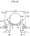
- the cooling means comprise a water bath 4c, which is fixed on the lower inner wall of the side plate 32 and receives a lower position of the stretching pulley 3a.
- the water bath 4c cools a non-holding portion of the stretching pulley 3a with water "W" stored therein.
- the stretch-width/stretch-ratio adjusting mechanism 4 comprises an inlet-side distance changing mechanism 4A for moving the support plates 3 and 3 in the direction of width of the film “F” to change the distance between the stretching pulleys 3a and 3a at the inlet side for the film "F”; and an outlet-side distance changing mechanism 4B for moving the support plates 3a and 3a in the direction of width of the film “F” to change the distance between the stretching pulleys 3a and 3a at the outlet side for the film "F".
- the inlet-side distance changing mechanism 4A comprises a pair of holders 41 and 41 rotatably mounted to projections 36 and 36 around shafts 41a and 41a, the projections 36 and 36 projecting from the support plates 31 and 31 opposite the horizontal base plates 31 and 31 at the inlet side for the film "F”; a first screw shaft 42 for adjusting stretch width supported in bearings 23 and 23 of the base 2 at the ends at the inlet for the film "F", reverse threads 42a and 42b in the middle being engaged with the holders 41 and 41; a second screw shaft 44 for assisting adjustment of stretch width connected to the first screw shaft 42 via a chain 43, the ends of the shaft 44 being supported in the upper side walls 11 and 11 of the housing 1, reverse threads 44a and 44b in the middle being engaged with spherical bearings (not shown) on the side plates 32 and 32 of the support plates 3 and 3.
- the outlet-side distance changing mechanism 4B comprises a pair of third screw shafts 45 and 45 for adjusting stretch ratio at the outlet side for the film "F", one end of the shaft 45 being shakably supported on automatically adjusting spherical bearings 22c and 22c of the base 2 (Fig.
- the handles for the third screw shafts 45 and 45 are rotated in an opposite direction, so that the support plates 3 and 3 are rotated around the holders 41 and 41 in the same direction to change an angle between the support plates 3 and 3.
- the hot-air generating device 5 comprises fans 51, heaters 52, a flow-regulater 53 and a louver 54.
- the two or more fans 51 and the heaters 54 are provided to face each other between the side plates 32 and 32 of the support plates 3 and 3. Air flow generated by the fans 51 is heated by the heaters to temperature suitable for spreading the film "F” to create hot air, which is blown against the flow regulater 53 by the rear fans 51 and 51.
- the flow regulater 53 is located like "V" between the heaters 52 and 52 to guide hot air from the heater to the louver 54, which comprises an upper longitudinal louver 54a and a lower lateral louver 54b between the flow-regulating plate 53 and the support plates 3.
- the angles of wind-direction regulating plates 54a1, 54a1...54b1, 54b1 in each louver 54a and 54b are adjusted, thereby regulating distribution of hot air which is blown against the middle of stretching path of the film "F".
- a pair of shutter plates 55 and 55 are slidably mounted at both ends of the lateral louvers 54b in the louver 54.
- the shutter plates 55 and 55 prevent hot air from leakage to the outside by sliding depending on the position of the support plate 3.
- the hot-air circulating passages 6 and 6 are provided at the inlet and outlet sides for the film "F" of the support plates 3 and 3.
- the hot-air circulating passage 6 at the inlet side of the film "F” comprises a front wall 12 of the housing 1; a sealing member 12a which extends to the side plates 32 and 32 of the support plates 3 and 3 at the lower end; and a pair of heat-resisting cloth bellows 61 and 61 fixed to the side plates 32 and 32 on the sealing member 12a.
- the bellows 61 is connected to the front wall 12 with magnets 61a at the side end to form a sealed passage which communicates with the fan 51 in the hot-air generating means 5.
- the hot-air circulating passage 6 at the outlet side "O" for the film “F” comprises a rear wall 13 of the housing 1; a sealing member 13a which extends to the side plates 32 and 32 of the support plates 3 and 3 at the lower end of the rear wall 13; and a pair of heat-resisting cloth bellows 62 and 62 fixed to the side edges of the side plates 32 and 32 on the sealing member 13a.
- the bellows 62 and 62 are connected to the front wall 12, thereby forming a sealing passage which communicates with the fan 51 in the hot-air generating device 5.
- a slight gap is formed between the sealing members 12a and 13a and the film "F", but air-flow to the outside is actually limited to a negligible extent owing to balance between discharge and supply with respect to the fan 51.
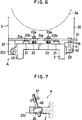
- the hot-air guide plate 7 between the support plates 3 and 3 comprises a fixed plate 7a supported via struts 72 on a support 71 fixed to the base 2, and moving plates 7b and 7b between which the fixed plate 7a are located.
- the fixed plate 7a comprises a plurality of plates arranged over the upper semicircle of the stretching pulley 31.
- the moving plates 7b are slidably connected to each plate of the fixed plate 7a, and are joined to one end of the wire 73 in the middle.
- the moving plates 7b are pushed by thrust means; that is to say, the moving plate 7b is pushed towards the stretching pulley 31 with a weight 75 at the other end of the wire 73 which suspends in the support 71 via pulleys 74 on the support 71, and casters 7c at the side of the moving plate 7b are slidable on the inner wall of the stretching pulley 3a.
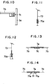
- a coil spring 75a or a hydraulic cylinder 75b may be connected to the other end of the wire 73 to push the moving plates 7b towards the stretching pulley 3a.
- a coil spring 76 may be located under the fixed plate 7 as shown in Fig. 13, or a hydraulic cylinder 77 may be located under the fixed plate 7a as shown in Fig. 14 to act against piston rods 77a and 77a, thereby pushing the moving plates 7b and 7b against the stretching pulleys 3a and 3a.
- the stretch-width/stretch-ratio adjusting mechanism 4 adjusts the distance or angle between the two support plates 3 and 3 to determine the stretch width or stretch ratio of the film "F" to be stretched
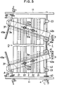
- the moving plates 7b and 7b move and engage with the inner walls of the stretching pulleys 3a and 3a depending on the distance and angle between the two support plates 3 and 3, as shown in Fig. 3.
- hot air is blown against the middle of stretching path of the film by the hot-air generating device 5, and flows over the surface of the film towards the inlet and outlet sides "I” and “O” to heat the film to uniform temperature. Thereafter, hot air passes through the hot-air circulating passages 6 and 6 and is sucked into the fan 51 in the hot-air generating device.
- the film "F” is permeable such as a slitted film
- hot air is blown against the middle of the film by the hot-air generating device and flows over the surface of the film towards the inlet and the outlet sides "I” and “O” for the film to heat the film to unform temperature.
- hot air which passes through the film flows along the hot-air guide plate 7 towards the inlet and outlet sides "I” and “O” and is sucked into the fan 51 in the hot-air generating device 5 through the hot-air circulating passages 6 and 6.
- hot air sucked into the fan 51 is heated to the original temperature by the heater 52 in the hot-air generating means 5.
- hot-air flow separating in the hot-air guide plate 7, sealing in the hot-air circulating passages 6 and 6 and sucking into the fan 51 in the hot-air generating device 5 could prevent hot air from leakage to the outside and could prevent cooling air from being sucked to the inside of the housing.
- the stretching machine according to the present invention is embodied as the foregoing structures, but is not limited to the embodiments. Various changes and modifications are possible within the scope of the claims as below.
- the above embodiment illustrates that the heater 52 is located in front of the fan 51 in the hot-air generating device 5, but, for example, the heater 52 may be located between the flow regulator 53 and the louver 53.
- the hot-air generating device 5 may be provided under the stretching pulleys 3a and 3b.
- the film “F” may be transferred on the lower arcuate portion of the stretching pulleys 3a and 3a.
- the film "F” held between the stretching pulley 3a and the circulating belt 3b is heated with hot air through the hot-air generating device 5 to a certain temperature.
- the stretching pulley 3a and the circulating belt 3b indirectly heated with hot air through the hot-air generating device 5 is cooled at non-held portion of the film "F" with water in the water bath 4c.
- both the stretching pulley 3a and the circulating belt 3a may be cooled as shown in Fig 5.
- hot air may flow upwardly or downwardly through an outside duct, or the film may be heated with a far-infrared heater.
- the stretching pulley 3a and the circulating belt 3b may be cooled with cooling air.
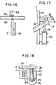
- a caster on the horizontal plates 31 and 31 of the support plates 3 and 3 so that the support plates may move on the base 2.
- a track rail 152 on which a number of steel balls 151 are embedded and a sliding member 153 which is slidable on the steel balls 151, and the support plates 3 and 3 may be suspended from the sliding member 153.
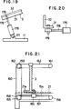
- the stretch-width/stretch-ratio adjusting mechanism 4 may be constructed as shown in Figs. 17 to 20.
- the inlet-side distance changing mechanism 4A comprise a base 2 having a guide rail 171 on which a slider 172 is slidably supported in a width direction.
- a projection 36 of the support plate 3 is rotatably connected to the slider 172 via a pin 173.
- a cylinder 174 is fixed to the base 2 and a rod 175 of the drive cylinder 174 is connected to the pin 173.
- the outlet-side distance changing mechanism 4B comprise a drive cylinder 176 rotatably connected to the side wall 11 of the housing 11 via a pin 177.
- the rod 178 of the drive cylinder 176 is rotatably connected to the horizontal base plate 31 at the outlet via a pin 179.
- the stretch-width/stretch-ratio adjusting mechanism 4 may be constructed as shown in Fig. 21.
- a guide rail 154 by which a slider 165 fixed to the lower part of the support plate 3 is slidably supported.
- Drive and follower sprockets 155 and 156 are provided by the ends of the guide rail 154.
- An endless chain 157 is wound around and between the drive and follower sprockets 155 and 156.
- a slider 165 is connected to the endless chain 157.
- a drive sprocket 8 is provided to rotate together with the drive sprocket 155.
- a follower sprocket 159 is provided above the drive sprocket 158, an endless chain 160 being wound around the sprockets 158 and 159.
- Above the follower sprocket 156 there is provided a follower sprocket 161, an endless chain 163 being wound around and between the follower sprockets 161 and 163 which rotates together with the follower sprocket 159.
- the upper end of the support plate 3 is mounted to the endless chain 162.
Landscapes
- Engineering & Computer Science (AREA)
- Mechanical Engineering (AREA)
- Shaping By String And By Release Of Stress In Plastics And The Like (AREA)
- Treatment Of Fiber Materials (AREA)
Applications Claiming Priority (6)
| Application Number | Priority Date | Filing Date | Title |
|---|---|---|---|
| JP222095/90 | 1990-08-23 | ||
| JP22209590A JP2983263B2 (ja) | 1990-08-23 | 1990-08-23 | 熱風循環式延伸機 |
| JP243146/90 | 1990-09-13 | ||
| JP24314690A JP2983270B2 (ja) | 1990-09-13 | 1990-09-13 | 延伸機 |
| JP256288/90 | 1990-09-26 | ||
| JP25628890A JP2985894B2 (ja) | 1990-09-26 | 1990-09-26 | 延伸機 |
Publications (3)
| Publication Number | Publication Date |
|---|---|
| EP0472393A2 true EP0472393A2 (de) | 1992-02-26 |
| EP0472393A3 EP0472393A3 (en) | 1992-07-29 |
| EP0472393B1 EP0472393B1 (de) | 1996-12-11 |
Family
ID=27330625
Family Applications (1)
| Application Number | Title | Priority Date | Filing Date |
|---|---|---|---|
| EP91307629A Expired - Lifetime EP0472393B1 (de) | 1990-08-23 | 1991-08-19 | Streckmaschine |
Country Status (10)
| Country | Link |
|---|---|
| US (1) | US5259097A (de) |
| EP (1) | EP0472393B1 (de) |
| KR (1) | KR940009904B1 (de) |
| AU (1) | AU634084B2 (de) |
| BR (1) | BR9103603A (de) |
| CA (1) | CA2049575C (de) |
| DE (1) | DE69123511T2 (de) |
| ES (1) | ES2096630T3 (de) |
| MY (1) | MY107324A (de) |
| TW (1) | TW204314B (de) |
Cited By (7)
| Publication number | Priority date | Publication date | Assignee | Title |
|---|---|---|---|---|
| US6800235B1 (en) | 2002-03-29 | 2004-10-05 | S & K Flooring | Carpet straightening apparatus |
| US7771185B2 (en) | 2002-03-29 | 2010-08-10 | S & K Carpet Specialist, Llc | Carpet straightening apparatus |
| US8871298B2 (en) | 2006-02-08 | 2014-10-28 | 3M Innovative Properties Company | Method for manufacturing on a film substrate at a temperature above its glass transition |
| WO2017167320A1 (de) * | 2016-03-30 | 2017-10-05 | Kiefel Gmbh | Verfahren und anlage zum behandeln eines in förderrichtung geförderten folienelements |
| CN109624291A (zh) * | 2018-11-27 | 2019-04-16 | 郑州大学 | 一种单层球形网架中三角形单元张膜装置 |
| US10384231B2 (en) | 2006-09-28 | 2019-08-20 | 3M Innovative Properties Company | System and method for controlling curl in multi-layer webs |
| CN110529452A (zh) * | 2019-07-15 | 2019-12-03 | 电子科技大学 | 一种共腔式气动绷膜机构 |
Families Citing this family (12)
| Publication number | Priority date | Publication date | Assignee | Title |
|---|---|---|---|---|
| DE19520513C1 (de) * | 1995-06-03 | 1996-07-25 | Kuesters Zittauer Maschf Gmbh | Breitstreckaggregat |
| EP0914933B1 (de) | 1997-11-04 | 2002-02-20 | Tenax S.p.A. | Verfahren zum Strecken von Kunststoff-Netzen und -Gittern |
| US6623679B2 (en) * | 2000-12-29 | 2003-09-23 | Eastman Kodak Company | Method of controlling width of polyester film support |
| US20020132196A1 (en) * | 2000-12-29 | 2002-09-19 | Eastman Kodak Company | Method of controlling width of polyester film support |
| JP2004027433A (ja) * | 2002-06-26 | 2004-01-29 | Nippon Petrochemicals Co Ltd | ウェブの拡幅装置 |
| US7384586B2 (en) | 2004-03-23 | 2008-06-10 | 3M Innovative Properties Company | Method for flexing a web |
| FI119286B (fi) * | 2006-03-28 | 2008-09-30 | Conenor Oy | Poikkisuuntainen venytyslaite |
| US7998534B2 (en) | 2006-09-28 | 2011-08-16 | 3M Innovative Properties Company | System and method for controlling curl in multi-layer webs |
| MX2012004101A (es) | 2009-10-09 | 2012-08-31 | Volm Companies Inc | Material de malla abierta y bolsas hechas del mismo. |
| US10758487B2 (en) | 2011-12-09 | 2020-09-01 | The Johns Hopkins University | Artificial antigen presenting cells having a defined and dynamic shape |
| CN114633460B (zh) * | 2022-05-16 | 2022-09-02 | 河南银金达新材料股份有限公司 | 一种聚酯膜的多向拉伸设备 |
| CN116330627B (zh) * | 2023-05-29 | 2023-08-01 | 天津市天缘电工材料股份有限公司 | 一种用于聚酰亚胺薄膜拉伸机运行轨道支撑结构 |
Family Cites Families (31)
| Publication number | Priority date | Publication date | Assignee | Title |
|---|---|---|---|---|
| US416343A (en) * | 1889-12-03 | Machine for tentering | ||
| DE91011C (de) * | ||||
| US49947A (en) * | 1865-09-12 | Improvement in cloth-drying machines | ||
| US436178A (en) * | 1890-09-09 | Lace-drier | ||
| DE213002C (de) * | ||||
| BE571136A (de) * | ||||
| US430749A (en) * | 1890-06-24 | Cloth-tentering machine | ||
| US1238742A (en) * | 1916-01-31 | 1917-09-04 | Ind Service And Equipment Company | Machine for stretching felt. |
| US1753025A (en) * | 1928-05-28 | 1930-04-01 | Claude L Roosevelt | Curtain drier and stretcher |
| US2595233A (en) * | 1950-02-17 | 1952-05-06 | Dungler Julien | Selvage guiding and drying apparatus |
| GB849436A (en) * | 1957-09-11 | 1960-09-28 | Ici Ltd | Synthetic polymer films |
| US3050816A (en) * | 1960-03-14 | 1962-08-28 | Mccreary John | High speed tenter chain device |
| BE595343A (de) * | 1960-09-26 | 1900-01-01 | ||
| US3179976A (en) * | 1962-09-05 | 1965-04-27 | Marshall And Williams Corp | Apparatus for stretching webs |
| GB1014765A (en) * | 1962-09-21 | 1965-12-31 | Emile Bernard Bates | Improvements in and relating to edge guiding and stentering of textile fabrics |
| FR1528036A (fr) * | 1966-05-02 | 1968-06-07 | Vepa Ag | Procédé et installation pour le traitement notamment de matières textiles en bandes |
| DE2024315A1 (en) * | 1970-05-19 | 1971-12-09 | Vepa Ag, Basel (Schweiz) | Fabric dryer with recirculating hot air system - and heated - calender rollers |
| US3722105A (en) * | 1971-07-06 | 1973-03-27 | Owens Illinois Inc | Apparatus and method for applying radio frequency energy to a moving web of material |
| US3762003A (en) * | 1972-01-24 | 1973-10-02 | Semcoe Holding Corp | Apparatus for distending and heat-treating tubular knitted fabric |
| US3902230A (en) * | 1972-06-16 | 1975-09-02 | Kimberly Clark Co | Simultaneous continuous biaxial web stretcher |
| IT1005999B (it) * | 1973-04-21 | 1976-09-30 | Vepa Ag | Dispositivo di trattamento termico di tessili |
| US4103403A (en) * | 1974-11-18 | 1978-08-01 | Marshall And Williams Company | Tenter guide rail gap crossing mechanism |
| JPS5730056A (en) * | 1980-07-30 | 1982-02-18 | Fuji Facom Corp | Failure processing system for data processing system |
| JPS58219024A (ja) * | 1982-06-15 | 1983-12-20 | Polymer Processing Res Inst | 膜・繊維材の延伸方法並びに装置 |
| JPH064275B2 (ja) * | 1985-05-20 | 1994-01-19 | ダイアホイルヘキスト株式会社 | フィルムの横延伸方法 |
| DE3616955A1 (de) * | 1986-05-20 | 1987-11-26 | Dornier Gmbh Lindauer | Folienreckmaschine mit mehreren aufeinanderfolgenden behandlungsfeldern |
| DE3621105A1 (de) * | 1986-06-24 | 1988-01-07 | Vdo Schindling | Verfahren zur uebertragung von informationen zwischen selbstaendigen teilnehmern eines systems ueber eine serielle schnittstelle und anordnung zur durchfuehrung des verfahrens |
| DE3621205A1 (de) * | 1986-06-25 | 1988-01-07 | Hoechst Ag | Verfahren zum herstellen von biaxial gestreckten flachfolien und vorrichtung hierfuer |
| DE3703097C1 (de) * | 1987-02-03 | 1988-01-21 | Dornier Gmbh Lindauer | Kluppenkettenbahn fuer endlos umlaufende Spannkluppen in Spannrahmen |
| DE3717774A1 (de) * | 1987-05-26 | 1988-12-08 | Brueckner Trockentechnik Gmbh | Spannmaschine zur waermebehandlung von breitgefuehrten warenbahnen |
| US4862564A (en) * | 1987-11-09 | 1989-09-05 | Mobil Oil Corporation | Apparatus for stretching a thermoplastic material web |
-
1991
- 1991-08-19 DE DE69123511T patent/DE69123511T2/de not_active Expired - Fee Related
- 1991-08-19 EP EP91307629A patent/EP0472393B1/de not_active Expired - Lifetime
- 1991-08-19 ES ES91307629T patent/ES2096630T3/es not_active Expired - Lifetime
- 1991-08-20 CA CA002049575A patent/CA2049575C/en not_active Expired - Fee Related
- 1991-08-20 AU AU82570/91A patent/AU634084B2/en not_active Ceased
- 1991-08-21 MY MYPI91001519A patent/MY107324A/en unknown
- 1991-08-22 BR BR919103603A patent/BR9103603A/pt not_active IP Right Cessation
- 1991-08-23 KR KR1019910014816A patent/KR940009904B1/ko not_active Expired - Fee Related
- 1991-08-23 US US07/749,555 patent/US5259097A/en not_active Expired - Fee Related
- 1991-09-26 TW TW080107639A patent/TW204314B/zh active
Cited By (11)
| Publication number | Priority date | Publication date | Assignee | Title |
|---|---|---|---|---|
| US6800235B1 (en) | 2002-03-29 | 2004-10-05 | S & K Flooring | Carpet straightening apparatus |
| US7513770B2 (en) | 2002-03-29 | 2009-04-07 | Hurst Kevin W | Carpet straightening apparatus |
| US7771185B2 (en) | 2002-03-29 | 2010-08-10 | S & K Carpet Specialist, Llc | Carpet straightening apparatus |
| US8871298B2 (en) | 2006-02-08 | 2014-10-28 | 3M Innovative Properties Company | Method for manufacturing on a film substrate at a temperature above its glass transition |
| US10384231B2 (en) | 2006-09-28 | 2019-08-20 | 3M Innovative Properties Company | System and method for controlling curl in multi-layer webs |
| WO2017167320A1 (de) * | 2016-03-30 | 2017-10-05 | Kiefel Gmbh | Verfahren und anlage zum behandeln eines in förderrichtung geförderten folienelements |
| AT521305A5 (de) * | 2016-03-30 | 2019-12-15 | Kiefel Gmbh | Verfahren und Anlage zum Behandeln eines in Förderrichtung geförderten Folienelements |
| AT521305B1 (de) * | 2016-03-30 | 2020-02-15 | Kiefel Gmbh | Verfahren und Anlage zum Behandeln eines in Förderrichtung geförderten Folienelements |
| CN109624291A (zh) * | 2018-11-27 | 2019-04-16 | 郑州大学 | 一种单层球形网架中三角形单元张膜装置 |
| CN110529452A (zh) * | 2019-07-15 | 2019-12-03 | 电子科技大学 | 一种共腔式气动绷膜机构 |
| CN110529452B (zh) * | 2019-07-15 | 2021-08-27 | 电子科技大学 | 一种共腔式气动绷膜机构 |
Also Published As
| Publication number | Publication date |
|---|---|
| DE69123511D1 (de) | 1997-01-23 |
| BR9103603A (pt) | 1992-05-12 |
| US5259097A (en) | 1993-11-09 |
| DE69123511T2 (de) | 1997-04-03 |
| AU634084B2 (en) | 1993-02-11 |
| TW204314B (de) | 1993-04-21 |
| MY107324A (en) | 1995-11-30 |
| ES2096630T3 (es) | 1997-03-16 |
| EP0472393B1 (de) | 1996-12-11 |
| CA2049575A1 (en) | 1992-02-24 |
| KR940009904B1 (ko) | 1994-10-18 |
| KR920004121A (ko) | 1992-03-27 |
| CA2049575C (en) | 1997-10-14 |
| AU8257091A (en) | 1992-05-14 |
| EP0472393A3 (en) | 1992-07-29 |
Similar Documents
| Publication | Publication Date | Title |
|---|---|---|
| US5259097A (en) | Stretching machine | |
| EP0062845B1 (de) | Verfahren und Vorrichtung zum Fördern streifenförmiger Materialien | |
| GB746386A (en) | Apparatus for stretching webs | |
| US4090911A (en) | Laminating apparatus | |
| US4226664A (en) | Laminating apparatus | |
| SE465213B (sv) | Anordning foer omvikning av kant paa en loepande materialbana | |
| CN1060253A (zh) | 拉幅机 | |
| CN208472384U (zh) | 一种拉幅定型机 | |
| JPH0681266A (ja) | まつすぐな製品を連続的に処理する装置 | |
| US3534393A (en) | Heat tunnel | |
| GB2137554A (en) | Plastic web for moulding | |
| JP2983263B2 (ja) | 熱風循環式延伸機 | |
| US2900220A (en) | Process for melt spinning and orienting polystyrene filaments | |
| US4808150A (en) | Oven-heated hot wheel sealing apparatus | |
| CN217275654U (zh) | 一种可调节风量的热收缩炉 | |
| US3438139A (en) | Apparatus for setting fabric | |
| CN211594074U (zh) | 一种用于清洗机的输送装置 | |
| US2599486A (en) | Heat-treating machine for textile material | |
| CN215952125U (zh) | 一种金属制品表面处理用烘干装置 | |
| JP2983275B2 (ja) | 延伸機 | |
| WO2005052694A2 (en) | Improvements in and relating to printing plate ovens | |
| CN116690958B (zh) | 一种热收缩薄膜纵横向拉伸装置 | |
| CN222226842U (zh) | 一种面料定型拉幅设备 | |
| JPH10273116A (ja) | 熱収縮包装装置とその制御方法 | |
| SU390340A1 (ru) | УСТРОЙСТВО дл ТЕРМООБРАБОТКИ ЛЕНТОЧНЫХ МАТЕРИАЛОВ, НАПРИМЕР КОРДНОГО ПОЛОТНА |
Legal Events
| Date | Code | Title | Description |
|---|---|---|---|
| PUAI | Public reference made under article 153(3) epc to a published international application that has entered the european phase |
Free format text: ORIGINAL CODE: 0009012 |
|
| 17P | Request for examination filed |
Effective date: 19910830 |
|
| AK | Designated contracting states |
Kind code of ref document: A2 Designated state(s): BE DE ES FR GB IT |
|
| PUAL | Search report despatched |
Free format text: ORIGINAL CODE: 0009013 |
|
| AK | Designated contracting states |
Kind code of ref document: A3 Designated state(s): BE DE ES FR GB IT |
|
| 17Q | First examination report despatched |
Effective date: 19940325 |
|
| GRAG | Despatch of communication of intention to grant |
Free format text: ORIGINAL CODE: EPIDOS AGRA |
|
| GRAH | Despatch of communication of intention to grant a patent |
Free format text: ORIGINAL CODE: EPIDOS IGRA |
|
| GRAH | Despatch of communication of intention to grant a patent |
Free format text: ORIGINAL CODE: EPIDOS IGRA |
|
| GRAA | (expected) grant |
Free format text: ORIGINAL CODE: 0009210 |
|
| AK | Designated contracting states |
Kind code of ref document: B1 Designated state(s): BE DE ES FR GB IT |
|
| REF | Corresponds to: |
Ref document number: 69123511 Country of ref document: DE Date of ref document: 19970123 |
|
| ET | Fr: translation filed | ||
| ITF | It: translation for a ep patent filed | ||
| REG | Reference to a national code |
Ref country code: ES Ref legal event code: FG2A Ref document number: 2096630 Country of ref document: ES Kind code of ref document: T3 |
|
| PLBE | No opposition filed within time limit |
Free format text: ORIGINAL CODE: 0009261 |
|
| STAA | Information on the status of an ep patent application or granted ep patent |
Free format text: STATUS: NO OPPOSITION FILED WITHIN TIME LIMIT |
|
| 26N | No opposition filed | ||
| PGFP | Annual fee paid to national office [announced via postgrant information from national office to epo] |
Ref country code: DE Payment date: 19990915 Year of fee payment: 9 |
|
| PGFP | Annual fee paid to national office [announced via postgrant information from national office to epo] |
Ref country code: BE Payment date: 20000718 Year of fee payment: 10 |
|
| PGFP | Annual fee paid to national office [announced via postgrant information from national office to epo] |
Ref country code: FR Payment date: 20000724 Year of fee payment: 10 |
|
| PGFP | Annual fee paid to national office [announced via postgrant information from national office to epo] |
Ref country code: GB Payment date: 20000810 Year of fee payment: 10 |
|
| PGFP | Annual fee paid to national office [announced via postgrant information from national office to epo] |
Ref country code: ES Payment date: 20000811 Year of fee payment: 10 |
|
| PG25 | Lapsed in a contracting state [announced via postgrant information from national office to epo] |
Ref country code: DE Free format text: LAPSE BECAUSE OF NON-PAYMENT OF DUE FEES Effective date: 20010501 |
|
| PG25 | Lapsed in a contracting state [announced via postgrant information from national office to epo] |
Ref country code: GB Free format text: LAPSE BECAUSE OF NON-PAYMENT OF DUE FEES Effective date: 20010819 |
|
| PG25 | Lapsed in a contracting state [announced via postgrant information from national office to epo] |
Ref country code: ES Free format text: LAPSE BECAUSE OF NON-PAYMENT OF DUE FEES Effective date: 20010820 |
|
| PG25 | Lapsed in a contracting state [announced via postgrant information from national office to epo] |
Ref country code: BE Free format text: LAPSE BECAUSE OF NON-PAYMENT OF DUE FEES Effective date: 20010831 |
|
| BERE | Be: lapsed |
Owner name: POLYMER PROCESSING RESEARCH INSTITUTE LTD Effective date: 20010831 Owner name: NIPPON PETROCHEMICALS CY LTD Effective date: 20010831 |
|
| GBPC | Gb: european patent ceased through non-payment of renewal fee |
Effective date: 20010819 |
|
| PG25 | Lapsed in a contracting state [announced via postgrant information from national office to epo] |
Ref country code: FR Free format text: LAPSE BECAUSE OF NON-PAYMENT OF DUE FEES Effective date: 20020430 |
|
| REG | Reference to a national code |
Ref country code: FR Ref legal event code: ST |
|
| REG | Reference to a national code |
Ref country code: ES Ref legal event code: FD2A Effective date: 20020911 |
|
| PG25 | Lapsed in a contracting state [announced via postgrant information from national office to epo] |
Ref country code: IT Free format text: LAPSE BECAUSE OF NON-PAYMENT OF DUE FEES;WARNING: LAPSES OF ITALIAN PATENTS WITH EFFECTIVE DATE BEFORE 2007 MAY HAVE OCCURRED AT ANY TIME BEFORE 2007. THE CORRECT EFFECTIVE DATE MAY BE DIFFERENT FROM THE ONE RECORDED. Effective date: 20050819 |