EP0472404A2 - Verbundwerkstoff mit Flüssigkristall, der eine verbesserte Doppelbrechung für Mikrowellen enthält - Google Patents
Verbundwerkstoff mit Flüssigkristall, der eine verbesserte Doppelbrechung für Mikrowellen enthält Download PDFInfo
- Publication number
- EP0472404A2 EP0472404A2 EP91307660A EP91307660A EP0472404A2 EP 0472404 A2 EP0472404 A2 EP 0472404A2 EP 91307660 A EP91307660 A EP 91307660A EP 91307660 A EP91307660 A EP 91307660A EP 0472404 A2 EP0472404 A2 EP 0472404A2
- Authority
- EP
- European Patent Office
- Prior art keywords
- liquid crystal
- particles
- microwave
- composite material
- phase modulating
- Prior art date
- Legal status (The legal status is an assumption and is not a legal conclusion. Google has not performed a legal analysis and makes no representation as to the accuracy of the status listed.)
- Withdrawn
Links
Images




Classifications
-
- C—CHEMISTRY; METALLURGY
- C09—DYES; PAINTS; POLISHES; NATURAL RESINS; ADHESIVES; COMPOSITIONS NOT OTHERWISE PROVIDED FOR; APPLICATIONS OF MATERIALS NOT OTHERWISE PROVIDED FOR
- C09K—MATERIALS FOR MISCELLANEOUS APPLICATIONS, NOT PROVIDED FOR ELSEWHERE
- C09K19/00—Liquid crystal materials
- C09K19/52—Liquid crystal materials characterised by components which are not liquid crystals, e.g. additives with special physical aspect: solvents, solid particles
-
- H—ELECTRICITY
- H03—ELECTRONIC CIRCUITRY
- H03C—MODULATION
- H03C7/00—Modulating electromagnetic waves
- H03C7/02—Modulating electromagnetic waves in transmission lines, waveguides, cavity resonators or radiation fields of antennas
- H03C7/022—Modulating electromagnetic waves in transmission lines, waveguides, cavity resonators or radiation fields of antennas using ferromagnetic devices, e.g. ferrites
Definitions
- This invention relates to microwave (including millimeter wave) devices, and, more particularly, to microwave phase modulation with a liquid crystal-based composite material.
- the index of refraction of many media is fixed and essentially constant, but there are "birefringent" media where the index of refraction of the material varies with relative orientation of a polarized wave and the medium.
- the birefringence of a uniaxial crystal is manifested by double angular displacements of a wave that passes through the medium.
- calcite crystals are birefringent to visible light, so that two differently positioned images are often seen when an object is viewed through a calcite crystal.
- the index of refractlon of some birefringent materials and of Kerr-effect isotropic materials can be controllably varied directionally by the application of a magnetic or electrical field to the medium.
- liquid crystals are known to be birefringent for visible light, and variable under the application of an electric field. This property has been used in liquid crystal light valves for use in color projection displays.
- birefringent materials have been known and used for controlling visible light, there are many potential applications for such materials in other portions of the electromagnetic spectrum such as the microwave range.
- viable birefringent and Kerr-effect materials are known for use in the visible-light frequency range, until recent years there have been known few if any practical Kerr-effect materials for microwave radiation.
- the most promising reported Kerr-effect materials for use in the microwave range are suspensions of highly asymmetric metallic particles in organic liquids. The birefringence of these suspensions is typically about 0.08 or less.
- the present invention provides a composite material whose microwave birefringence is equal to or greater than that of either of the components of the material.
- This material is readily fabricated and can be used in a variety of phase modulating application where the index of refraction must be controllably varied by applied external fields.
- the composite material is utilized in devices and processes that require controllable phase modulation by changing the microwave index of refraction. These devices are in many cases more compact and less expensive than conventional devices used for the same purposes.
- a microwave phase modulating cell comprises a microwave wave guide; a phase modulating medium disposed within the wave guide, the phase modulating medium comprising a liquid crystal having a dispersion of electrically conducting, elongated particles therein; and means for controllably aligning the particles and the liquid crystal in a first direction in the phase modulating medium.
- the phase modulating medium within the microwave wave guide is a composite of electrically conducting, elongated particles dispersed within a liquid crystal.
- the means for controllably aligning is preferably a pair of transverse, oppositely disposed electrodes across which a voltage is applied.
- the applied voltage transverse to the wave propagation direction causes the elongated particles and the molecules of a positive dielectric anisotropy liquid crystal to align transverse to the wave propagation direction, achieving an index of refraction that is different from that of the randomly oriented particles and liquid crystal.
- a second means for controllably aligning is provided to realign the particles and the liquid crystals in another direction.
- the index of refraction of the cell is rapidly and controllably varied through the two means for controllably aligning.
- the present Invention therefore provides a phase modulating medium with a high microwave birefringence, and a cell construction that can be tuned to modulate the microwave.
- Directional transmitters, receivers, and the like can be constructed without necessarily requiring moving parts, and at a fraction of the cost and size of equivalent prior devices.
- a liquid crystal-based composite material comprises a liquid crystal having a dispersion of electrically conducting, elongated particles therein.
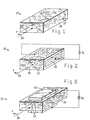
- Figure 1 depicts a composite material 20 formed from elongated, electrically conducting particles 22 dispersed throughout a liquid crystal 24.
- the elongated, rod-like particles may be any type of electrically conducting material, including but not limited to solid metals and metal-coated nonmetals.
- Metal-coated nonmetals such as metal coated organic microtubes (also sometimes called "microtubules") are preferred, because they have a density more nearly that of the liquid crystal and therefore are not as subject to gravity-driven segregation as are solid metals.
- the particles are nickel-coated hollow cylinders of lecithin macromolecules having an average length of about 10 micrometers, an average diameter of about 0.8 micrometers, and an external coating of nickel about 0.1 micrometer thick.
- a preferred concentration of the particles is at least about 0.2 volume percent of the composite material 20.
- the liquid crystal can be any liquid crystal material whose molecules align under an applied magnetic or electrical field, including nematic, cholesteric, and smectic liquid crystals.
- the liquid crystal preferably has a positive dielectric anisotropy and a positive magnetic anisotropy.
- a preferred liquid crystal is ROTN-404, a nematic liquid crystal which is a mixture of cyanobiphenyls and cyanophenylpyrimidines, available commercially from Hoffmann-LaRoche.
- a preferred composite material is prepared by mixing the nickel-coated microtubes into the liquid crystal.
- the elongated particles 22 and the molecules of the liquid crystal 24 are initially randomly oriented in the composite material 20, as illustrated in Figure 1.
- two opposing electrodes 26 are placed on either side of the composite material 20, as illustrated in Figure 2.
- a voltage V1 is applied between the electrodes 26, the particles 22 and the molecules of the liquid crystal 24 align parallel to the field vector between the electrodes 26.
- the electrodes 26 are preferably placed so that when the voltage V1 is applied there is an electric field formed that is transverse to a microwave wave propagation direction 28 of a microwave having a polarization vector P, so that the particles 22 and the molecules of the liquid crystal 24 align in a direction perpendicular to the propagation direction 28.
- This condition of alignment may be viewed as a first aligned state, to be distinguished from the randomly oriented state of Figure 1.
- a second means for aligning the particles and the molecules of the liquid crystal is provided.
- the second means could be another set of electrodes similar to that of Figure 2, except oriented with the field vector between the electrodes at a different angle to the microwave polarization direction P.
- Figure 3 illustrates an alternative approach to the second means for aligning the particles and the liquid crystal, which is preferred for use when the particles are nickel-coated microtubes or the particles are otherwise responsive to a magnetic field.
- a set of opposing magnet or electromagnet pole pieces 30 are placed on either side of the composite material 20, preferably such that the vector between the pole pieces 30 is perpendicular to the propagation direction 28 and also perpendicular to the vector between the electrodes 26.
- the electrodes 26 are not shown in Figure 3 for clarity of illustration, but normally both the electrodes 26 and the pole pieces 30 would be present, as will be discussed for the structure of Figure 4.
- the nickel metal of the microtube particles is ferromagnetic, and aligns with the magnetic field produced by the pole pieces when a voltage V2 is applied to the windings of the pole pieces.
- the molecules of the liquid crystal also align with the magnetic field, so that both the particles and the liquid crystal molecules realign to the second state parallel to the vector between the pole pieces 30.
- a method for modulating the phase of a microwave comprises the steps of providing a microwave phase modulating cell comprising a phase modulating medium, the phase modulating medium comprising a liquid crystal having a dispersion of electrically conducting, elongated particles therein, and means for controllably aligning the particles and the liquid crystal in a selected direction in the phase modulating medium; directing a beam of microwave energy through the cell in a microwave propagation direction; and operating the means for controllably aligning the particles and the liquid crystal, thereby changing the microwave index of refraction of the phase modulating medium.
- the particles can also be ferromagnetic to react with a magnetic field.
- a modulating cell 31 is illustrated in Figure 4.
- the cell 31 includes a microwave wave guide 32, which is a hollow metal tube, usually rectangular in cross section, that is dimensioned for the propagation of microwaves therein.
- microwaves have wavelengths of from about 30 centimeters (1 GHz frequency) to about 3 centimeters (100 GHz frequency), and include the frequencies commonly termed microwaves and millimeter waves. Standard microwave wave guides with appropriate dimensions for the selected wavelength are available commercially.
- the wave guide 32 normally has a mounting flange 33 on each end thereof.
- the waveguide 32 has dimensions indicated for use with 30 GHz microwaves.
- the height A of the wave guide 32 is about 0.35 centimeters
- the width B is about 0.7 centimeters
- the length C is about 10 centimeters.
- Other dimensions which are well known in the art, are used for other microwave frequencies.
- An interior cavity 34 of the wave guide 32 is filled with the composite material of electrically conducting, elongated particles dispersed in a liquid crystal, as discussed previously.
- the ends of the cavity 34 are closed with polyester windows 35 about 0.3 millimeters thick.
- Apertures are cut into two opposing faces 36 of the rectangular wave guide 32, and opposing electrodes 26 are mounted therein. Apertures are cut into the other two opposing faces 37 of the wave guide 32, and opposing electromagnet pole pieces 30 mounted therein.
- the electrodes 26 are connected to voltage source V1, and the windings of the pole pieces 30 are connected to voltage source V2, in the manner discussed previously.
- a polarized microwave beam is directed through the wave guide 32, entering and leaving the wave guide 32 through the windows 35.
- the index of refraction of the composite medium within the wave guide 32, relative to the microwave beam, is controlled by adjusting the voltages V1 and V2.
- voltage V2 to the electromagnets is maintained zero and the voltage V1 to the electrodes is increased to align the particles and the molecules of the liquid crystal perpendicular to the faces 36.
- V1 is reduced to zero and V2 is gradually increased to align the particles and the molecules of the liquid crystal perpendicular to the faces 37.
- the phase velocity of the microwave is altered as the voltages are changed, and the index of refraction of the medium within the phase modulating cell is also altered. Simultaneous application of the voltages V1 and V2 is used to achieve intermediate alignment directions.
- phase modulating cells like that of Figure 4 were constructed to evaluate the composite material of the invention.
- the magnetic field was applied with a permanent magnet rather than an electromagnet.
- a composite material medium containing 0.2 percent by weight of the nickel-coated microtubes, which were about 0.8 micrometers in diameter with an average length of about 10 micrometers, in ROTN-404 liquid crystal was prepared and placed into each of the phase modulating cells.
- a similar series of tests was performed using only the ROTN-404 liquid crystal as the medium.
- the microwave wave had a frequency of 30 GHz, and standard WR-28 wave guides were used.
- a standard Mach-Zehnder microwave phase bridge such as that shown in the publication "Nonlinear microwave susceptibility measurement of an artificial Kerr medium” by Bradley Bobbs et al., Appl. Phys. Lett. , vol. 52, no. 1, January 4, 1984, at pages 4-6, was used for the measurements.
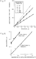
- Figure 5 depicts the phase shift of the microwave as a function of the path length, that is, the length of microwave travel through the composite medium.
- the upper line is for the composite material having electrically conducting, elongated particles in the liquid crystal, while the lower line is for the liquid crystal material only.
- the liquid crystal with a dispersion of elongated, electrically conducting particles achieves substantially increased phase shifting over the liquid crystal material. From these data, the birefringence of the composite material medium is about 0.22, and the birefringence of the liquid crystal material is about 0.152.
- the total of the birefringence of the liquid crystal material (0.152) plus the birefringence of the elongated particles (0.04) in an isotropic medium, which is the expected total birefringence for the composite material, is about 0.192.
- the actual measured birefringence for the composite material, from Figure 5, is about 0.22.
- the measured birefringence is therefore about 15 percent greater than the predicted birefringence, a completely unexpected result.
- phase modulating test cells were made similar to that of Figure 4, except that the field alignment was applied just by a 3 kilogauss magnetic field from a permanent magnet which was rotated 90 degrees in position about the cell, and thence 90 degrees to the polarization vector of the 30 kHz microwave, which remained constant.
- the cells were filled with various pathlengths of ROTN-404 liquid crystal containing 0, 0.2, 0.3, and 0.6 weight percent, respectively, of nickel-coated microtubes about 0.8 micrometers in diameter with an average length of about 10 micrometers.
- Figure 7 shows the birefringence phase shift change measured from rotating the magnetic field from parallel to perpendicular to the microwave polarization direction in the waveguide cell.
- Figure 8 presents a direct comparison of the birefringence as a function of concentration of the same nickel-coated microtubules in the ROTN-404 liquid crystal (data from Figure 7) and in paraffin wax oil.
- the liquid crystal composites have a much higher birefringence than the isotropic composites.
- the birefringence increases more rapidly with concentration of these metal particles in the liquid crystal composites than in the isotropic composites.
- Anisotropic conductive particles form much more stable dispersions in liquid crystals than in isotropic fluids. Long-lasting suspensions and dispersions are obtained in liquid crystals for such anisotropic particles shorter than about 5 micrometers in length. Suspensions of larger particles, such as the 10 micrometer metallized microtubes described above, are much more stable in liquid crystals but they do gradually settle out under ambient gravity although relatively little agitation is required to keep them in suspension.
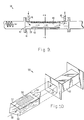
- a flow cell waveguide modulator 38 of the type shown in Figure 9 can be used with liquid crystal composites both to keep the conductive particles suspended and to obtain a different refractive index for the microwave travelling in the flow direction than when an orthogonal electric field is applied across this microwave modulating cell as indicated in Figure 9.
- the flow cell 38 includes a wave guide 39 defining a cavity 40 with a flange 41 at either end for joining to other lengths of waveguide.
- a window 42 closes each end of the cavity 40.
- a pair of opposing electrodes 43 are disposed on either side of the cavity 40, and another pair of electrodes or magnet pole pieces (not shown) may be placed on the opposing sides of the cavity displaced by 90 degrees with respect to the electrodes 43.
- a continuous flow of the mixture of microtubes and liquid crystal enters the cavity 40 through an inlet line 44 and leaves the cavity 40 through an exit line 45. The microtubes in the liquid crystal cannot settle in any substantial amount to form vertical segregation during this continuous flow.
- the approach of the invention may be used in conjunction with other techniques applicable to devices. These approaches include use of polymer dispersed liquid crystals to achieve prealignment of the liquid crystal director in a direction perpendicular to the microwave electromagnetic polarization for the off-state of PDLCs with liquid crystals of positive dielectric anisotropy, and use of high applied electric fields in the 1-20 kilovolt per centimeter range by having higher applied voltages and/or multilayer electrodes within the waveguide cell to provide smaller spacings between electrodes.
- a preferred form of a cell 50 using a polymer dispersed liquid crystal microwave phase modulating medium 52 is illustrated in disassembled form in Figure 10.
- the medium 52 is a free-standing piece of the polymer dispersed liquid crystal (PDLC) material.
- the PDLC material is prepared as described in US Patent 4,688,900 or 4,435,047, whose disclosures are incorporated by reference, except that the conventional liquid crystal material is replaced by a mixture of microtubes and liquid crystal as described herein.
- Ends 54 through which the microwave wave enters and leaves the medium 52 are angled.
- Two oppositely disposed electrode plates 56 are attached directly to the lateral sides of the medium 52, such that the electric field vector is perpendicular to the wave path 58.
- the electrode plates 56 function in precisely the same manner as the electrodes 26 discussed previously.
- a second set of electrode plates, or magnetic pole pieces may be provided on the other oppositely disposed lateral faces.
- the entire medium 52 is assembled, and slid lengthwise into a cavity 60 of a conventional length of microwave wave guide 62 to form the cell 50.
- the wave guide is available commercially and is generally as described previously.
- This cell 50 is then bolted into a longer waveguide or used as a component of an array, or as otherwise might be needed.
- the medium 52 may also be readily used without a separate wave guide, as, for example, part of a large array of separately controllable media in an antenna or other device.
- the field strength in the mixture of microtubes and liquid crystal transverse to the wave path in volts per unit length is an important factor in determining response time of the microwave phase modulating cell. Even for fairly small microwave wave guides of less than one centimeter internal size, the applied voltage must be quite high to attain a large field strength.
- FIG. 11 An approach to increasing the field strength and reducing the response time is illustrated in Figure 11.
- a plurality of pairs of opposing electrodes 70 are provided as part of a medium 72.
- the electrodes 70 are arranged as a series of plates in an interdigitated form, with alternating plates being oppositely charged relative to some intermediate value by connection to a voltage source V3.
- the electrodes are preferably prepared on thin dielectric substrates such as glass or polyester films, covered with a conductive metal coating such as aluminum.
- the electrodes 70 are spaced closely together. Even with a modest applied voltage V3 that is readily produced with an inexpensive power supply, the electric field strength of the field between the electrodes is very large due to the small denominator in the definition of field strength, volts divided by electrode spacing.
- a thin layer 74 of liquid crystal is sandwiched between each pair of electrodes 70, to complete the medium 72.
- the liquid crystal material can be in unconstrained liquid form, or in an encapsulated form such as a polymer dispersed liquid crystal. In the former case, the edges of the medium 72 may be sealed with a polymer adhesive to prevent loss of liquid crystal, or the entire medium 72 may be placed inside a wave guide that is in turn sealed.
- FIGS 12 and 13 illustrate a tunable slot array antenna 80 having a wave guide 82 with a liquid crystal composite medium 84 therein. There are lateral openings or slots 86 in the sides of the wave guide 82.
- the slot array antenna 80 operates according to the principles of the antenna disclosed in US Patent 4,613,869, which disclosure is incorporated by reference. However, instead of an expensive ferrite tunable core, the less expensive microtube/liquid crystal mixture 84 of the invention is used.
- Electrodes 88 are placed in apertures on the sides of the wave guide 80, as shown in Figure 13. An orthogonal magnetic field can be applied externally.
- the application of a voltage to the electrodes 88 alters the orientation of the microtubes and the molecules in the liquid crystal, which in turn interact with the microwave to modify its wavelength in the wave guide lg.
- the angle A that satisfies the relation changes, thereby permitting the direction of the antenna to be changed by controlling the voltage applied to the electrodes 88.
- Figures 14 and 15 illustrate an array of microwave phase modulating cells that controls the sweeping of a radome 100.
- a plurality of individually controllable cells 102 each containing the microtube/liquid crystal composite material, is arranged in a locus, which may be flat, semicircular, or otherwise curved.
- a microwave beam 104 is directed outwardly from a source 106.
- Figure 14 the beam passes through the radome 100 in a diffuse form.
- Figure 15 each is individually controlled to deflect the impinging portion of the beam 104 by an amount appropriate to form a deflected beam 108 that is aimed at some preselected location.
- the cells 102 may be programmed to keep the deflected beam 108 aimed at the preselected location. For example, if the radome is on a ship that rolls from side to side, the voltages applied to the cells 102 may be varied based upon a measurement of the roll and under control of a microprocessor to maintain the beam 108 aimed at the preselected location. While such an aimable radome antenna was possible with prior phase modulating systems, those systems were prohibitively expensive or did not have the stability required to ensure predictable operation.
- a two-dimensional microwave beam steering spatial phase modulator 120 can be constructed based upon the external electric field modulation of the effective refractive index of the microtube/liquid crystal composite material.
- a series of parallel thin metal electrode plates 122 are stacked with narrow spacings between them. The spacings are filled with a composite liquid crystal media 124, as in Figure 16.
- V1, V2, V3, V4, V5 the wave front of a microwave propagating in the plane of the electrodes 122 can be reshaped and hence the microwave beam direction changed.
- the P vector of the microwave should be perpendicular to the plane of the electrodes.
- the spacing between the electrodes 122 should be on the order of 100 micrometers or less. In this configuration, the angular deflection of the beam is proportional to the applied field strength.
- the microwave beam modulator 120 is typically used to steer a beam radiated from a horn or any other radiating antenna.
- Figure 17 shows an example of its application for a horn antenna 128.
- the modulator 120 is placed in front or inside the flare of the horn of the antenna 128, with the plane of the electrodes 122 perpendicular to the electric field vector of the radiating beam. On activating the electrodes 122, the radiating beam will be deflected in the plane that contains the electric field vector.
Landscapes
- Chemical & Material Sciences (AREA)
- Crystallography & Structural Chemistry (AREA)
- Engineering & Computer Science (AREA)
- Materials Engineering (AREA)
- Organic Chemistry (AREA)
- Physics & Mathematics (AREA)
- Electromagnetism (AREA)
- Liquid Crystal (AREA)
- Waveguide Switches, Polarizers, And Phase Shifters (AREA)
- Variable-Direction Aerials And Aerial Arrays (AREA)
Applications Claiming Priority (2)
| Application Number | Priority Date | Filing Date | Title |
|---|---|---|---|
| US57350390A | 1990-08-24 | 1990-08-24 | |
| US573503 | 1990-08-24 |
Publications (2)
| Publication Number | Publication Date |
|---|---|
| EP0472404A2 true EP0472404A2 (de) | 1992-02-26 |
| EP0472404A3 EP0472404A3 (en) | 1993-03-03 |
Family
ID=24292252
Family Applications (1)
| Application Number | Title | Priority Date | Filing Date |
|---|---|---|---|
| EP19910307660 Withdrawn EP0472404A3 (en) | 1990-08-24 | 1991-08-20 | Liquid crystal-based composite material having enhanced microwave birefringence |
Country Status (2)
| Country | Link |
|---|---|
| EP (1) | EP0472404A3 (de) |
| JP (1) | JPH04245803A (de) |
Cited By (5)
| Publication number | Priority date | Publication date | Assignee | Title |
|---|---|---|---|---|
| US5431142A (en) * | 1993-02-18 | 1995-07-11 | Robert Bosch Gmbh | Fuel injection system for internal combustion engines |
| WO2000051231A3 (en) * | 1999-02-24 | 2000-11-30 | Ericsson Telefon Ab L M | Ferroelectric modulator |
| WO2011036243A1 (de) * | 2009-09-25 | 2011-03-31 | Technische Universität Darmstadt | Phasenschieber für hochfrequenz-signale |
| CN111316500A (zh) * | 2017-10-30 | 2020-06-19 | 韦弗有限责任公司 | 多层液晶相位调制器 |
| US11264684B2 (en) | 2018-04-13 | 2022-03-01 | Boe Technology Group Co., Ltd. | Liquid crystal phase shifter comprising a liquid crystal cell with first and second substrates separated by a partition plate having first and second microstrips on opposing surfaces of the plate |
Families Citing this family (5)
| Publication number | Priority date | Publication date | Assignee | Title |
|---|---|---|---|---|
| WO1999043036A1 (fr) * | 1998-02-20 | 1999-08-26 | Sumitomo Electric Industries, Ltd. | Dephaseur et antenne a balayage |
| JP3943450B2 (ja) * | 2002-06-26 | 2007-07-11 | 株式会社リコー | 光偏向装置、光偏向方法および画像表示装置 |
| GB0608055D0 (en) * | 2006-04-24 | 2006-05-31 | Univ Cambridge Tech | Liquid crystal devices |
| US12519218B2 (en) | 2021-03-30 | 2026-01-06 | Nec Corporation | Liquid crystal antenna and method for manufacturing liquid crystal antenna |
| CN119816999A (zh) * | 2022-09-14 | 2025-04-11 | 华为技术有限公司 | 用于估计输入信号到达角的包括可调天线的接收器 |
Family Cites Families (4)
| Publication number | Priority date | Publication date | Assignee | Title |
|---|---|---|---|---|
| US2532157A (en) * | 1944-10-31 | 1950-11-28 | Rca Corp | Variable reactive microwave device |
| US3631501A (en) * | 1970-02-16 | 1971-12-28 | Gen Dynamics Corp | Microwave phase shifter with liquid dielectric having metallic particles in suspension |
| US4701024A (en) * | 1985-12-02 | 1987-10-20 | Dai-Ichi Seiko Kabushiki Kaisha | Liquid crystal material including magnetic particles and method of producing the same |
| US4911981A (en) * | 1987-06-16 | 1990-03-27 | Schnur Joel M | Metal clad lipid microstructures |
-
1991
- 1991-08-20 EP EP19910307660 patent/EP0472404A3/en not_active Withdrawn
- 1991-08-23 JP JP21247091A patent/JPH04245803A/ja active Pending
Cited By (9)
| Publication number | Priority date | Publication date | Assignee | Title |
|---|---|---|---|---|
| US5431142A (en) * | 1993-02-18 | 1995-07-11 | Robert Bosch Gmbh | Fuel injection system for internal combustion engines |
| WO2000051231A3 (en) * | 1999-02-24 | 2000-11-30 | Ericsson Telefon Ab L M | Ferroelectric modulator |
| US6518850B1 (en) | 1999-02-24 | 2003-02-11 | Telefonaktiebolaget Lm Ericsson | Ferroelectric modulator |
| WO2011036243A1 (de) * | 2009-09-25 | 2011-03-31 | Technische Universität Darmstadt | Phasenschieber für hochfrequenz-signale |
| EP2309585A1 (de) * | 2009-09-25 | 2011-04-13 | Technische Universität Darmstadt | Phasenschieber für Hochfrequenz-Signale |
| CN111316500A (zh) * | 2017-10-30 | 2020-06-19 | 韦弗有限责任公司 | 多层液晶相位调制器 |
| EP3704760A4 (de) * | 2017-10-30 | 2021-12-22 | Wafer, LLC | Mehrschichtiger flüssigkristallphasenmodulator |
| CN111316500B (zh) * | 2017-10-30 | 2024-01-30 | 韦弗有限责任公司 | 多层液晶相位调制器 |
| US11264684B2 (en) | 2018-04-13 | 2022-03-01 | Boe Technology Group Co., Ltd. | Liquid crystal phase shifter comprising a liquid crystal cell with first and second substrates separated by a partition plate having first and second microstrips on opposing surfaces of the plate |
Also Published As
| Publication number | Publication date |
|---|---|
| EP0472404A3 (en) | 1993-03-03 |
| JPH04245803A (ja) | 1992-09-02 |
Similar Documents
| Publication | Publication Date | Title |
|---|---|---|
| US5184233A (en) | Liquid crystal-based composite material including electrically conducting elongated particles and having enhanced microwave birefringence | |
| EP0472403A2 (de) | Mikrowellen-Phasenmodulation mit Flüssigkristallen | |
| US5194972A (en) | Microwave phase modulation with liquid crystals | |
| US3694053A (en) | Nematic liquid crystal device | |
| Lim et al. | Liquid crystal millimeter wave electronic phase shifter | |
| KR102490705B1 (ko) | 구형파 신호 조정 기능을 갖는 안테나 어레이 | |
| Clark et al. | Director and layer structure of SSFLC cells | |
| EP1463787B1 (de) | Material für eine flüssigkristallzelle | |
| EP0472404A2 (de) | Verbundwerkstoff mit Flüssigkristall, der eine verbesserte Doppelbrechung für Mikrowellen enthält | |
| US5313562A (en) | Optical device with electrodes end-to-end with electric field causing homeotropic alignment of liquid crystal in space between ends | |
| EP0041184B1 (de) | Flüssigkristallanzeige (FKA) und Verfahren zu ihrer Herstellung | |
| EP0032362A1 (de) | Elektro-optische Vorrichtung mit einem chiralen smektischen Flüssigkristall und Verfahren zu ihrer Herstellung | |
| US3631501A (en) | Microwave phase shifter with liquid dielectric having metallic particles in suspension | |
| Lim et al. | Liquid crystal birefringence for millimeter wave radar | |
| US7030834B2 (en) | Active magnetic radome | |
| Yang et al. | Determination of the permittivity of nematic liquid crystals in the microwave region | |
| Sahu et al. | Electric field driven controllable motility of metal-dielectric Janus particles with boojum defects in thin films of a nematic liquid crystal | |
| Maclennan et al. | Solitary waves in ferroelectric liquid crystals | |
| Fujikake et al. | Thick polymer-stabilized liquid crystal films for microwave phase control | |
| US20070188668A1 (en) | Liquid-crystal-absed retardation-free terahertz phase shifter | |
| US7595850B2 (en) | Stressed liquid crystals materials for light modulation | |
| Huh et al. | Prewavy pattern: a director-modulation structure in nematic liquid crystals | |
| US9400412B2 (en) | Nanosecond liquid crystalline optical modulator | |
| US6686984B1 (en) | Polarization control device | |
| US20050146769A1 (en) | Magneto-optical devices |
Legal Events
| Date | Code | Title | Description |
|---|---|---|---|
| PUAI | Public reference made under article 153(3) epc to a published international application that has entered the european phase |
Free format text: ORIGINAL CODE: 0009012 |
|
| AK | Designated contracting states |
Kind code of ref document: A2 Designated state(s): DE FR GB IT |
|
| PUAL | Search report despatched |
Free format text: ORIGINAL CODE: 0009013 |
|
| AK | Designated contracting states |
Kind code of ref document: A3 Designated state(s): DE FR GB IT |
|
| 17P | Request for examination filed |
Effective date: 19930809 |
|
| STAA | Information on the status of an ep patent application or granted ep patent |
Free format text: STATUS: THE APPLICATION HAS BEEN WITHDRAWN |
|
| 18W | Application withdrawn |
Withdrawal date: 19941020 |