EP0472477B1 - Betätigungsmechanismus mit Trennvorrichtung für elektrischen Schalter - Google Patents
Betätigungsmechanismus mit Trennvorrichtung für elektrischen Schalter Download PDFInfo
- Publication number
- EP0472477B1 EP0472477B1 EP19910420274 EP91420274A EP0472477B1 EP 0472477 B1 EP0472477 B1 EP 0472477B1 EP 19910420274 EP19910420274 EP 19910420274 EP 91420274 A EP91420274 A EP 91420274A EP 0472477 B1 EP0472477 B1 EP 0472477B1
- Authority
- EP
- European Patent Office
- Prior art keywords
- handle
- stop
- operating mechanism
- circuit breaker
- mechanism according
- Prior art date
- Legal status (The legal status is an assumption and is not a legal conclusion. Google has not performed a legal analysis and makes no representation as to the accuracy of the status listed.)
- Expired - Lifetime
Links
- 230000005540 biological transmission Effects 0.000 claims description 19
- 238000003466 welding Methods 0.000 claims description 14
- 230000000903 blocking effect Effects 0.000 claims description 9
- 230000007935 neutral effect Effects 0.000 description 6
- 238000005476 soldering Methods 0.000 description 4
- 238000006073 displacement reaction Methods 0.000 description 2
- 210000003127 knee Anatomy 0.000 description 2
- 238000004519 manufacturing process Methods 0.000 description 2
- 238000006243 chemical reaction Methods 0.000 description 1
- 239000012141 concentrate Substances 0.000 description 1
- 230000000694 effects Effects 0.000 description 1
- 230000005489 elastic deformation Effects 0.000 description 1
- 238000009434 installation Methods 0.000 description 1
Images
Classifications
-
- H—ELECTRICITY
- H01—ELECTRIC ELEMENTS
- H01H—ELECTRIC SWITCHES; RELAYS; SELECTORS; EMERGENCY PROTECTIVE DEVICES
- H01H71/00—Details of the protective switches or relays covered by groups H01H73/00 - H01H83/00
- H01H71/10—Operating or release mechanisms
- H01H71/50—Manual reset mechanisms which may be also used for manual release
- H01H71/501—Means for breaking welded contacts; Indicating contact welding or other malfunction of the circuit breaker
-
- H—ELECTRICITY
- H01—ELECTRIC ELEMENTS
- H01H—ELECTRIC SWITCHES; RELAYS; SELECTORS; EMERGENCY PROTECTIVE DEVICES
- H01H9/00—Details of switching devices, not covered by groups H01H1/00 - H01H7/00
- H01H9/20—Interlocking, locking, or latching mechanisms
- H01H9/28—Interlocking, locking, or latching mechanisms for locking switch parts by a key or equivalent removable member
- H01H2009/288—Provisions relating to welded contacts
-
- H—ELECTRICITY
- H01—ELECTRIC ELEMENTS
- H01H—ELECTRIC SWITCHES; RELAYS; SELECTORS; EMERGENCY PROTECTIVE DEVICES
- H01H71/00—Details of the protective switches or relays covered by groups H01H73/00 - H01H83/00
- H01H71/10—Operating or release mechanisms
- H01H71/50—Manual reset mechanisms which may be also used for manual release
- H01H71/56—Manual reset mechanisms which may be also used for manual release actuated by rotatable knob or wheel
Definitions
- the invention relates to a control mechanism of an electric circuit breaker equipped with a knee switch with neutral passage and a pair of fixed and movable contacts per pole, and comprising a kinematic chain having an operating handle that can be moved between a closed position and an open position corresponding respectively to the closed state, and to the open state of the contacts, and a cutting device allowing in the event of manual opening and welding of the contacts, the locking of the handle in an intermediate position located between the open neutral position and the open position, said sectioning device being provided with a transmission unit of the kinematic chain cooperating with a stop for limiting the stroke of, the handle for the indication of soldering of the contacts in said intermediate position.
- circuit breakers with pivoting handles have an integrated sectioning function preventing padlocking in the open position by mechanical locking of the handle in one position intermediate if the contacts are soldered.
- the locking device essentially involves the trajectories of the kinematic chain, which imposes strict manufacturing tolerances increasing the cost of the circuit breaker.
- an actuating block transmits the rotary movement from the handle to the pivoting handle of the circuit breaker, via an amplifier mechanical formed by a cam and control drawer assembly.
- the object of the invention is to improve the device for sectioning a circuit breaker mechanism to reduce the manufacturing cost and increase safety.
- the mechanism is characterized in that the sectioning device comprises an elastically extensible mechanical connection, which undergoes a deformation when passing from a first rest position to a second locking position after the neutral knee switch has passed, so to generate a relative movement between the transmission member and the stop when the operating force exerted on the handle exceeds a predetermined threshold.
- the transmission member of the sectioning device comprises a bent lever, having a first end wedged on a rotary control shaft, a second end driven by a boss of the rotary handle, and a lug of locking fixed to the deformable intermediate zone of the lever, so as to come to hang on a fixed stop in the second locking position.
- the intermediate zone of the lever is connected to the first end by a narrowed section calibrated to allow permanent deformation in the event of welding of the contacts.
- the handle then remains immobilized in the intermediate position, thereby preventing padlocking.
- the sectioning device is integrated in a control block, rotatable at the level of an elastic drawer having a stopper capable of cooperating with a pin for locking a cam of a control rotary.
- the presence of the sectioning device in the adaptable rotary control unit makes it possible to reinforce the mechanical resistance of the mechanism in the event of welding of the contacts, given the proximity of the locking zone of the handle.
- a rotary handle 10 of a toggle control mechanism of an electric circuit breaker with molded insulating housing is associated with a kinematic chain 12 capable of transmitting the rotational movements of the handle 10 to a switching bar (not shown) for manual opening and closing of the circuit breaker.
- the circuit breaker comprises a toggle mechanism, capable of occupying a position for closing the contacts, a position for opening the contacts, and an intermediate tripping position open on fault.
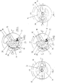
- the kinematic chain 12 comprises a transmission part or member 14 formed by an angled lever having, a first end 16 wedged coaxially on a rotary control shaft 18, and a second end 20 driven by a boss 22 of the handle 10.
- the intermediate zone of the transmission part 14 is provided with a locking lug 24 capable of occupying a rest position or a blocking position as a function of the operating force necessary to make turn the shaft 18 by the manual action of the handle 10 in the opening direction.
- the first end 16 of the transmission part 14 is connected to the intermediate zone by a narrowed section 26 allowing a radial elastic deformation of the part 14 according to the value of the moment of the operating torque.
- the lug 24 cooperates with a fixed stop 28 for limiting the stroke of the handle 10.
- the stop 28 is constituted, for example, by a circular rib formed in the cover of the molded insulating housing.
- the calibration of the narrowed section 26 of the transmission part 14 makes it possible to precisely choose the time of passage of the lug 24 from the rest position to the blocking position.
- the location of the stop 28 on the housing allows the locking of the handle 10 in an intermediate position S situated between the PMO position of neutral position opening, and the position O opening (FIG. 4).
- the rib of the stop 28 has a radius slightly greater than that of the lug 24 when the latter is in the rest position in the event of non-deformation of the transmission part (FIG. 2).
- the handle 10 is in position F corresponding to the closing of the contacts of the circuit breaker.
- the manual opening of the contacts takes place by rotation of the handle 10 clockwise, indicated by the arrow F1.
- the boss 22 of the handle 10 drives the control shaft 18 in the same direction by means of the transmission part 14.
- the moment of the operating torque increases in the direction of opening of the handle 10.
- the radial deformation of the transmission part 14 occurs when the torque exceeds a predetermined threshold , which depends on the size of the narrowed section 26.
- the locking pin 24 is biased towards the position of blocking, and comes to hang on the stop 28 when the handle 10 arrives in the intermediate position S after passing the neutral opening PMO, ( Figure 4).
- the handle 10 then remains immobilized in this position S, and any attempt at forced displacement towards the open position O is made impossible.
- the deformation of the transmission part 14 takes place exclusively in the event of soldering of the contacts, and after passage of the PMO opening neutral position following the manual movement of the handle 10 in the opening direction.
- the positive locking of the handle 10 in the intermediate position S prevents any padlocking, and constitutes an indicator of the welded state of the circuit breaker.
- the transmission part 14 constitutes an elastically extensible mechanical connection which can be incorporated into the mechanism of any circuit breaker with insulated housing molded with or without remote control unit.
- the transmission part 14 can be arranged at any point of the kinematic chain 12 between the rotary handle 10 and the switching bar.
- the rotary control shaft 18 can be part of a remote control unit adaptable to a circuit breaker with pivoting lever, as described in French patent application 89.14632.
- the shaft 18 is coupled to a drive cam 31 cooperating with a control slide 32 (see Figures 5 to 11 below) of the pivoting lever.
- the rotary handle 10 is arranged on the front face of the remote control unit, and serves as a manual emergency control.
- the transmission part 14 is located between the boss 22 of the rotary handle 10 and the upper end of the control shaft 18, inside the remote control unit.
- the direct reaction of the lug 24 on the fixed stop 28 of the housing makes it possible to concentrate the locking action in the vicinity of the handle 10.
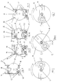
- the cutting device 130 is located in the remote control unit at the level of the control slide 32, that is to say at the lower end of the rotary shaft 18 of the pivoting lever of the circuit breaker.
- the elastic structure of the drawer 32 comprises a first lower slide 34, having an opening in which the pivoting lever engages, and a second slide 36 equipped with two rollers 38.40, cooperating with the drive cam 31 associated with the shaft 18.
- a spring system 42 allows a relative sliding movement between the two slides 34, 36.
- the overtravel d (FIG. 10) resulting from this relative movement is used to produce the cutting device 130, which comprises a locking pin 44, integral with the drive cam 31, and a stop cleat 46 integral with the first slide. 34 of the elastic drawer 32.
- the calibration of the spring system 42 determines the overtravel between the two slides 34, 36 as a function of the operating force exerted on the drawer 32 during manual opening or closing by the handle 10.
- the manual opening of the circuit breaker is effected by rotation of the handle 10 by half a turn in the direction of the arrow F1.
- the cam 31 follows the manual movement of the handle 10, and drives the translational control slide 32 in the direction of the arrow F2 (see FIG. 9).
- the effort of maneuver is normal and the two slides 34, 36 of the drawer 32 move simultaneously.
- the pin 44 is free to pass in front of the stop cleat 46 which is in an inactive position of rest.
- the handle 10 and the cam 31 and drawer 32 assembly can then reach the open position O shown in FIGS. 7 and 11. Lockout is possible thanks to the pull tab 30 of the handle 10.
- the calibration threshold of the spring system 42 is exceeded due to the increasing operating force.
- the appearance of the overtravel d results from the displacement of the first slide 34 relative to the second slide 36 which remains stationary.
- the stopper 46 follows the movement of the first slide 34 during the overtravel d, so as to stop the locking pin 44 when the cam 31 arrives in the position of FIG. 10, corresponding to the intermediate position S of the handle 10 (figure 6).
- the handle 10 remains immobilized in the intermediate position S which is located as in FIGS. 1 to 4, between the PMO opening dead center and the opening O position.
- the sectioning function of the circuit breaker is reported in the part of the mechanism belonging to the rotary remote or manual control unit, that is to say between the pivoting lever of the circuit breaker, and the rotary handle. .
Landscapes
- Breakers (AREA)
Claims (9)
- Antriebsmechanismus für einen Leistungsschalter, der mit einem Kniegelenk mit Kippunktdurchlauf sowie pro Pol mit einem feststehenden und einem beweglichen Kontakt ausgerüstet ist und eine kinematische Kette (12) mit einem zwischen einer Einschaltstellung (F) und einer Ausschaltstellung (O) entsprechend dem geschlossenen bzw. geöffneten Zustand der Kontakte verstellbaren Betätigungsgriff (10) sowie eine Trennvorrichtung (13, 130) aufweist, die bei manueller Ausschaltung und bei verschweißten Kontakten das Blockieren des Betätigungsgriffs (10) in einer zwischen der Ausschalt-Kippunktlage (PMO) und der Ausschaltstellung (O) liegenden Zwischenstellung (S) ermöglicht, wobei die genannte Trennvorrichtung (13, 130) ein Übertragungselement (14, 31, 44) der kinematischen Kette (12) umfaßt, das mit einem Anschlag (28, 46) zur Begrenzung des Hubs des Betätigungsgriffs (10) zusammenwirkt, um das Verschweißen der Kontakte in der genannten Zwischenstellung (S) anzuzeigen,
dadurch gekennzeichnet, daß die Trennvorrichtung (13, 130) eine elastisch dehnbare Verbindung aufweist, die beim Übergang von einer ersten Ruhestellung in eine zweite Blockierstellung nach dem Überschreiten des Kippunkts des Kniegelenks eine Verformung erfährt, so daß eine relative Verschiebung zwischen dem Übertragungselement (14, 31, 44) und dem Anschlag (28, 46) erfolgt, wenn die auf den Betätigungsgriff (10) ausgeübte Kraft einen bestimmten Grenzwert übersteigt. - Antriebsmechanismus nach Anspruch 1, dadurch gekennzeichnet, daß die genannte elastisch dehnbare Verbindung der Trennvorrichtung (13, 130) in das im Innern des Isolierstoffgehäuses des Leistungsschalters angeordnete Kniegelenk integriert ist.
- Antriebsmechanismus nach Anspruch 1, dadurch gekennzeichnet, daß die genannte elastisch dehnbare Verbindung der Trennvorrichtung (13, 130) in die kinematische Kette (12) eines an das Gehäuse des Leistungsschalters anbaubaren Antriebsblocks zur Fern- oder Handbetätigung integriert ist.
- Antriebsmechanismus nach Anspruch 2 oder 3, dadurch gekennzeichnet, daß das Übertragungselement der Trennvorrichtung (13) einen Kniehebel mit einem ersten, auf einer Antriebswelle (18) montierten Ende (16), einem zweiten, durch eine Mitnehmernase (22) des Drehgriffs (10) beaufschlagten Ende (20) sowie einem am verformbaren Mittelbereich des Kniehebels befestigten Verriegelungsvorsprung (24) aufweist, derart daß der Hebel in der zweiten Blockierstellung durch einen feststehenden Anschlag (28) zurückgehalten wird.
- Antriebsmechanismus nach Anspruch 4, dadurch gekennzeichnet, daß der Mittelbereich des Kniehebels mit dem ersten Ende (16) über einen Abschnitt mit verjüngtem Querschnitt (26) verbunden ist, welcher so bemessen ist, daß bei verschweißten Kontakten eine bleibende Verformung eintritt.
- Antriebsmechanismus nach Anspruch 4 oder 5, dadurch gekennzeichnet, daß der ortsfeste Anschlag (28) zur Begrenzung des Hubs des Drehgriffs (10) durch eine an das Gehäuse angeformte kreisbogenförmige Rippe gebildet wird, die koaxial zur Antriebswelle (28) angeordnet ist und einen größeren bzw. kleineren Radius aufweist als der Verriegelungsvorsprung (24), wenn dieser sich in der ersten Ruhestellung bzw. in der zweiten Blockierstellung befindet.
- Antriebsmechanismus nach Anspruch 3, dadurch gekennzeichnet, daß das Übertragungselement (130) einen Verriegelungsstift (44) aufweist, der auf einer Kurvenscheibe (31) einer an den Drehgriff (10) angekoppelten Antriebswelle (18) angeordnet ist, und daß die Kurvenscheibe (31) mit einem elastischen Betätigungsschieber (32) zusammenwirkt, der eine, in der zweiten Blockierstellung einen Anschlag für den Verriegelungsstift (44) bildende Sperrast (46) umfaßt.
- Antriebsmechanismus nach Anspruch 7, dadurch gekennzeichnet, daß der Betätigungsschieber (32) ein erstes, an den Kipphebel des Leistungsschalters angekoppeltes und mit der genannten Sperrast (46) versehenes Gleitstück (34) sowie ein zweites Gleitstück (36) mit Rollen (38, 40) umfaßt, die mit der Kurvenscheibe (31) zusammenwirken, und daß eine Federanordnung (42) zwischen den beiden Gleitstücken (34, 36) angeordnet ist, um einen Überhub d während der Relativbewegung in die zweite Blockierstellung zu erzeugen.
- Antriebsmechanismus nach Anspruch 8, dadurch gekennzeichnet, daß sich der Überhub d aus der Verschiebung des ersten Gleitstücks (34) bei in seiner Stellung verharrendem zweiten Gleitstück (36) ergibt, und daß die Sperrast (46) der Verschiebungsbewegung des ersten Gleitstücks (34) folgt, um die Kurvenscheibe (31) durch den Verriegelungsstift (44) zu blockieren, wenn der Drehgriff (10) in die Zwischenstellung (S) gelangt.
Applications Claiming Priority (2)
| Application Number | Priority Date | Filing Date | Title |
|---|---|---|---|
| FR9010665A FR2666168B1 (fr) | 1990-08-23 | 1990-08-23 | Mecanisme de commande a dispositif de sectionnement pour disjoncteur electrique. |
| FR9010665 | 1990-08-23 |
Publications (2)
| Publication Number | Publication Date |
|---|---|
| EP0472477A1 EP0472477A1 (de) | 1992-02-26 |
| EP0472477B1 true EP0472477B1 (de) | 1995-09-20 |
Family
ID=9399856
Family Applications (1)
| Application Number | Title | Priority Date | Filing Date |
|---|---|---|---|
| EP19910420274 Expired - Lifetime EP0472477B1 (de) | 1990-08-23 | 1991-07-24 | Betätigungsmechanismus mit Trennvorrichtung für elektrischen Schalter |
Country Status (4)
| Country | Link |
|---|---|
| EP (1) | EP0472477B1 (de) |
| DE (1) | DE69113179T2 (de) |
| ES (1) | ES2079615T3 (de) |
| FR (1) | FR2666168B1 (de) |
Cited By (1)
| Publication number | Priority date | Publication date | Assignee | Title |
|---|---|---|---|---|
| CN1881495B (zh) * | 2005-06-14 | 2010-07-28 | 施耐德电器工业公司 | 带有可转动锁定装置的电开关设备的致动器 |
Families Citing this family (1)
| Publication number | Priority date | Publication date | Assignee | Title |
|---|---|---|---|---|
| CN109378232B (zh) * | 2018-11-06 | 2024-01-23 | 安士缔(中国)电气设备有限公司 | 一种应用于消防泵星三角降压启动的机械强制启动装置 |
Family Cites Families (5)
| Publication number | Priority date | Publication date | Assignee | Title |
|---|---|---|---|---|
| US2937254A (en) * | 1957-02-05 | 1960-05-17 | Gen Electric | Panelboard unit |
| FR2378345A1 (fr) * | 1977-01-24 | 1978-08-18 | Merlin Gerin | Disjoncteur electrique a poignee rotative a grand angle de deplacement |
| FR2436491A1 (fr) * | 1978-09-12 | 1980-04-11 | Merlin Gerin | Disjoncteur electrique multipolaire basse tension a blocs auxiliaires de commande |
| US4399420A (en) * | 1981-09-11 | 1983-08-16 | Square D Company | Main circuit breaker |
| DE3217255C1 (de) * | 1982-05-07 | 1983-06-09 | Siemens AG, 1000 Berlin und 8000 München | Schalterantriebsvorrichtung für Lasttrennschalter in Mittelspannungsanlagen |
-
1990
- 1990-08-23 FR FR9010665A patent/FR2666168B1/fr not_active Expired - Fee Related
-
1991
- 1991-07-24 EP EP19910420274 patent/EP0472477B1/de not_active Expired - Lifetime
- 1991-07-24 DE DE1991613179 patent/DE69113179T2/de not_active Expired - Fee Related
- 1991-07-24 ES ES91420274T patent/ES2079615T3/es not_active Expired - Lifetime
Cited By (1)
| Publication number | Priority date | Publication date | Assignee | Title |
|---|---|---|---|---|
| CN1881495B (zh) * | 2005-06-14 | 2010-07-28 | 施耐德电器工业公司 | 带有可转动锁定装置的电开关设备的致动器 |
Also Published As
| Publication number | Publication date |
|---|---|
| FR2666168B1 (fr) | 1992-10-30 |
| EP0472477A1 (de) | 1992-02-26 |
| DE69113179T2 (de) | 1996-04-18 |
| FR2666168A1 (fr) | 1992-02-28 |
| DE69113179D1 (de) | 1995-10-26 |
| ES2079615T3 (es) | 1996-01-16 |
Similar Documents
| Publication | Publication Date | Title |
|---|---|---|
| EP0342133B1 (de) | Betätigungsmechanismus für Kleinschalter mit Anzeige einer Kontaktschweissung | |
| EP2436020B1 (de) | Schnapp- und rasteinrichtung in einem schalter oder unterbrecherschalter | |
| EP0612087B1 (de) | Fernbetätigter Schutzschalter mit Abtrennfunktion | |
| EP0140761A2 (de) | Antriebsmechanismus für einen mehrpoligen Niederspannungs-Schutzschalter | |
| EP0224396A1 (de) | Steuermechanismus für Niederspannungslastschalter | |
| EP1975971B1 (de) | Bedienungsvorrichtung eines elektrischen Sicherungsgeräts und elektrisches Sicherungsgerät, das sie umfasst | |
| EP0633591A1 (de) | Betätigungsmechanismus für elektrischen Modulschutzschalter | |
| FR2534412A1 (fr) | Interrupteur electrique avec arret de course du levier de commande en cas de soudure des contacts | |
| EP0205361B1 (de) | Handbetätigte Schnapp-Schliesseinrichtung eines Miniaturschutzschalters | |
| EP2061058B1 (de) | Steuervorrichtung für ein elektrisches Unterbrechungsgerät und elektrisches Unterbrechungsgerät, das damit ausgestattet ist | |
| EP0326446B1 (de) | Steuer- und Signalhilfsschalter für mehrpoligen Modulschalter | |
| EP2131378A1 (de) | Steuervorrichtung für ein elektrisches Unterbrechungsgerät, das mit einer Signalisierungsvorrichtung für die Verschweißung der Kontakte ausgestattet ist, und mit dieser Vorrichtung ausgestattetes elektrisches Unterbrechungsgerät | |
| EP0161946B1 (de) | An einen Schutzschalter ankuppelbare Zusatzeinheit | |
| EP0286474B1 (de) | Antrieb für einen Dreistellungsschalter | |
| EP0408466B1 (de) | Betätigungsmechanismus für elektrischen Schalter | |
| EP0612092B1 (de) | Schutzschalter mit anpassbarer Fernbetätigungseinheit | |
| EP0472477B1 (de) | Betätigungsmechanismus mit Trennvorrichtung für elektrischen Schalter | |
| EP0901142A1 (de) | Anzeigevorrichtung für elektrische fähler in eine Schaltvorrichtung, wie ein Differentialschutzschalter | |
| EP2061060B1 (de) | Elektrisches Schaltgerät wie etwa ein Leistungsschalter oder Schalter | |
| FR3051593B1 (fr) | Dispositif de signalisation d'un defaut electrique dans un appareil de protection electrique, et appareil de protection electrique comportant un tel dispositif. | |
| BE897953A (fr) | Interrupteur electrique sectionnable perfectionne | |
| EP0602024B1 (de) | Betätigungsmechanismus für einen mehrpoligen Fehlerstromschutzschalter mit drehbarer Schaltwelle | |
| FR2656155A1 (fr) | Auxiliaire d'adaptation pour interrupteur differentiel multipolaire. | |
| EP3815119A1 (de) | Manuelle steuervorrichtung für einen fernbedienten quellenwechselrichter | |
| FR2659791A1 (fr) | Dispositif interrupteur auxiliaire pour un disjoncteur de protection de moteur a commande manuelle. |
Legal Events
| Date | Code | Title | Description |
|---|---|---|---|
| PUAI | Public reference made under article 153(3) epc to a published international application that has entered the european phase |
Free format text: ORIGINAL CODE: 0009012 |
|
| AK | Designated contracting states |
Kind code of ref document: A1 Designated state(s): BE CH DE ES GB IT LI SE |
|
| 17P | Request for examination filed |
Effective date: 19920707 |
|
| 17Q | First examination report despatched |
Effective date: 19940426 |
|
| RAP1 | Party data changed (applicant data changed or rights of an application transferred) |
Owner name: SCHNEIDER ELECTRIC SA |
|
| GRAA | (expected) grant |
Free format text: ORIGINAL CODE: 0009210 |
|
| AK | Designated contracting states |
Kind code of ref document: B1 Designated state(s): BE CH DE ES GB IT LI SE |
|
| REF | Corresponds to: |
Ref document number: 69113179 Country of ref document: DE Date of ref document: 19951026 |
|
| ITF | It: translation for a ep patent filed | ||
| GBT | Gb: translation of ep patent filed (gb section 77(6)(a)/1977) |
Effective date: 19951127 |
|
| REG | Reference to a national code |
Ref country code: ES Ref legal event code: FG2A Ref document number: 2079615 Country of ref document: ES Kind code of ref document: T3 |
|
| PLBE | No opposition filed within time limit |
Free format text: ORIGINAL CODE: 0009261 |
|
| STAA | Information on the status of an ep patent application or granted ep patent |
Free format text: STATUS: NO OPPOSITION FILED WITHIN TIME LIMIT |
|
| 26N | No opposition filed | ||
| PGFP | Annual fee paid to national office [announced via postgrant information from national office to epo] |
Ref country code: SE Payment date: 19970716 Year of fee payment: 7 |
|
| PGFP | Annual fee paid to national office [announced via postgrant information from national office to epo] |
Ref country code: ES Payment date: 19970729 Year of fee payment: 7 |
|
| PGFP | Annual fee paid to national office [announced via postgrant information from national office to epo] |
Ref country code: CH Payment date: 19970806 Year of fee payment: 7 |
|
| PGFP | Annual fee paid to national office [announced via postgrant information from national office to epo] |
Ref country code: BE Payment date: 19970911 Year of fee payment: 7 |
|
| PG25 | Lapsed in a contracting state [announced via postgrant information from national office to epo] |
Ref country code: SE Free format text: LAPSE BECAUSE OF NON-PAYMENT OF DUE FEES Effective date: 19980725 Ref country code: ES Free format text: LAPSE BECAUSE OF NON-PAYMENT OF DUE FEES Effective date: 19980725 |
|
| PG25 | Lapsed in a contracting state [announced via postgrant information from national office to epo] |
Ref country code: LI Free format text: LAPSE BECAUSE OF NON-PAYMENT OF DUE FEES Effective date: 19980731 Ref country code: CH Free format text: LAPSE BECAUSE OF NON-PAYMENT OF DUE FEES Effective date: 19980731 Ref country code: BE Free format text: LAPSE BECAUSE OF NON-PAYMENT OF DUE FEES Effective date: 19980731 |
|
| BERE | Be: lapsed |
Owner name: S.A. SCHNEIDER ELECTRIC Effective date: 19980731 |
|
| REG | Reference to a national code |
Ref country code: CH Ref legal event code: PL |
|
| EUG | Se: european patent has lapsed |
Ref document number: 91420274.2 |
|
| PGFP | Annual fee paid to national office [announced via postgrant information from national office to epo] |
Ref country code: DE Payment date: 19990708 Year of fee payment: 9 |
|
| PGFP | Annual fee paid to national office [announced via postgrant information from national office to epo] |
Ref country code: GB Payment date: 19990721 Year of fee payment: 9 |
|
| PG25 | Lapsed in a contracting state [announced via postgrant information from national office to epo] |
Ref country code: GB Free format text: LAPSE BECAUSE OF NON-PAYMENT OF DUE FEES Effective date: 20000724 |
|
| GBPC | Gb: european patent ceased through non-payment of renewal fee |
Effective date: 20000724 |
|
| PG25 | Lapsed in a contracting state [announced via postgrant information from national office to epo] |
Ref country code: DE Free format text: LAPSE BECAUSE OF NON-PAYMENT OF DUE FEES Effective date: 20010501 |
|
| REG | Reference to a national code |
Ref country code: ES Ref legal event code: FD2A Effective date: 19990811 |
|
| PG25 | Lapsed in a contracting state [announced via postgrant information from national office to epo] |
Ref country code: IT Free format text: LAPSE BECAUSE OF NON-PAYMENT OF DUE FEES Effective date: 20050724 |