EP0472816A1 - Appareil et méthode de chargement de matériaux en forme de feuille - Google Patents
Appareil et méthode de chargement de matériaux en forme de feuille Download PDFInfo
- Publication number
- EP0472816A1 EP0472816A1 EP91107303A EP91107303A EP0472816A1 EP 0472816 A1 EP0472816 A1 EP 0472816A1 EP 91107303 A EP91107303 A EP 91107303A EP 91107303 A EP91107303 A EP 91107303A EP 0472816 A1 EP0472816 A1 EP 0472816A1
- Authority
- EP
- European Patent Office
- Prior art keywords
- container
- carriage
- shuttle
- assembly
- moving
- Prior art date
- Legal status (The legal status is an assumption and is not a legal conclusion. Google has not performed a legal analysis and makes no representation as to the accuracy of the status listed.)
- Granted
Links
- 239000000463 material Substances 0.000 title claims abstract description 70
- 238000000034 method Methods 0.000 title claims description 22
- 230000000712 assembly Effects 0.000 description 32
- 238000000429 assembly Methods 0.000 description 32
- 230000007246 mechanism Effects 0.000 description 16
- 238000010276 construction Methods 0.000 description 15
- 239000012530 fluid Substances 0.000 description 9
- 230000000694 effects Effects 0.000 description 8
- 230000004913 activation Effects 0.000 description 1
- 239000000969 carrier Substances 0.000 description 1
- 230000000977 initiatory effect Effects 0.000 description 1
- 230000037361 pathway Effects 0.000 description 1
- 230000002441 reversible effect Effects 0.000 description 1
Images





Classifications
-
- B—PERFORMING OPERATIONS; TRANSPORTING
- B62—LAND VEHICLES FOR TRAVELLING OTHERWISE THAN ON RAILS
- B62B—HAND-PROPELLED VEHICLES, e.g. HAND CARTS OR PERAMBULATORS; SLEDGES
- B62B3/00—Hand carts having more than one axis carrying transport wheels; Steering devices therefor; Equipment therefor
- B62B3/008—Hand carts having more than one axis carrying transport wheels; Steering devices therefor; Equipment therefor having more than two axes
-
- B—PERFORMING OPERATIONS; TRANSPORTING
- B65—CONVEYING; PACKING; STORING; HANDLING THIN OR FILAMENTARY MATERIAL
- B65H—HANDLING THIN OR FILAMENTARY MATERIAL, e.g. SHEETS, WEBS, CABLES
- B65H31/00—Pile receivers
- B65H31/24—Pile receivers multiple or compartmented, e.d. for alternate, programmed, or selective filling
-
- B—PERFORMING OPERATIONS; TRANSPORTING
- B65—CONVEYING; PACKING; STORING; HANDLING THIN OR FILAMENTARY MATERIAL
- B65H—HANDLING THIN OR FILAMENTARY MATERIAL, e.g. SHEETS, WEBS, CABLES
- B65H31/00—Pile receivers
- B65H31/30—Arrangements for removing completed piles
- B65H31/3036—Arrangements for removing completed piles by gripping the pile
- B65H31/3045—Arrangements for removing completed piles by gripping the pile on the outermost articles of the pile for clamping the pile
-
- B—PERFORMING OPERATIONS; TRANSPORTING
- B62—LAND VEHICLES FOR TRAVELLING OTHERWISE THAN ON RAILS
- B62B—HAND-PROPELLED VEHICLES, e.g. HAND CARTS OR PERAMBULATORS; SLEDGES
- B62B2202/00—Indexing codes relating to type or characteristics of transported articles
- B62B2202/64—Documents, files or paper sheets
-
- B—PERFORMING OPERATIONS; TRANSPORTING
- B65—CONVEYING; PACKING; STORING; HANDLING THIN OR FILAMENTARY MATERIAL
- B65H—HANDLING THIN OR FILAMENTARY MATERIAL, e.g. SHEETS, WEBS, CABLES
- B65H2301/00—Handling processes for sheets or webs
- B65H2301/40—Type of handling process
- B65H2301/42—Piling, depiling, handling piles
- B65H2301/422—Handling piles, sets or stacks of articles
- B65H2301/4224—Gripping piles, sets or stacks of articles
- B65H2301/42242—Gripping piles, sets or stacks of articles by acting on the outermost articles of the pile for clamping the pile
-
- B—PERFORMING OPERATIONS; TRANSPORTING
- B65—CONVEYING; PACKING; STORING; HANDLING THIN OR FILAMENTARY MATERIAL
- B65H—HANDLING THIN OR FILAMENTARY MATERIAL, e.g. SHEETS, WEBS, CABLES
- B65H2301/00—Handling processes for sheets or webs
- B65H2301/40—Type of handling process
- B65H2301/42—Piling, depiling, handling piles
- B65H2301/422—Handling piles, sets or stacks of articles
- B65H2301/4225—Handling piles, sets or stacks of articles in or on special supports
- B65H2301/42254—Boxes; Cassettes; Containers
-
- B—PERFORMING OPERATIONS; TRANSPORTING
- B65—CONVEYING; PACKING; STORING; HANDLING THIN OR FILAMENTARY MATERIAL
- B65H—HANDLING THIN OR FILAMENTARY MATERIAL, e.g. SHEETS, WEBS, CABLES
- B65H2402/00—Constructional details of the handling apparatus
- B65H2402/30—Supports; Subassemblies; Mountings thereof
- B65H2402/35—Supports; Subassemblies; Mountings thereof rotating around an axis
- B65H2402/351—Turntables
-
- Y—GENERAL TAGGING OF NEW TECHNOLOGICAL DEVELOPMENTS; GENERAL TAGGING OF CROSS-SECTIONAL TECHNOLOGIES SPANNING OVER SEVERAL SECTIONS OF THE IPC; TECHNICAL SUBJECTS COVERED BY FORMER USPC CROSS-REFERENCE ART COLLECTIONS [XRACs] AND DIGESTS
- Y10—TECHNICAL SUBJECTS COVERED BY FORMER USPC
- Y10S—TECHNICAL SUBJECTS COVERED BY FORMER USPC CROSS-REFERENCE ART COLLECTIONS [XRACs] AND DIGESTS
- Y10S414/00—Material or article handling
- Y10S414/10—Associated with forming or dispersing groups of intersupporting articles, e.g. stacking patterns
- Y10S414/102—Associated with forming or dispersing groups of intersupporting articles, e.g. stacking patterns including support for group
Definitions
- the present invention relates to a new and improved apparatus and method for use in sequentially loading sheet material articles into a plurality of compartments in each of a plurality of containers.
- This patent discloses an endless conveyor which has carriers adapted to travel along a pathway to support containers for receiving newspapers.
- a pair of spaced transfer conveyors are adapted to sequentially receive and then return containers to the endless conveyor.
- the containers are positioned at a loading station by an indexing member.
- the present invention provides a new and improved apparatus and method for sequentially loading sheet material articles into a plurality of compartments in each of a plurality of containers.
- the container is moved to a first or infeed shuttle assembly.
- the empty container is transferred from the infeed shuttle assembly to a carriage assembly.
- the transfer of the empty container from the infeed shuttle assembly to the carriage assembly may be accomplished by moving the shuttle assembly and carriage assembly into an overlapping relationship.
- the infeed shuttle assembly and carriage assembly may then be moved vertically relative to each other to transfer the empty container from the shuttle assembly to the carriage assembly.
- each of the compartments in the empty container is filled in turn with sheet material articles while the container is supported by the carriage assembly.
- the carriage assembly is movable relative to a loader or stacker assembly to sequentially position the compartments of the container at a loading station.
- the carriage assembly may advantageously be operated to move the empty container along a linear path and to rotate the container about a vertical axis.
- the container is transferred from the carriage assembly to a second or outfeed shuttle assembly. This may be accomplished by moving the outfeed shuttle assembly into an overlapping relationship with the carriage assembly and providing vertical movement between the loaded container and the outfeed shuttle assembly. The carriage assembly and outfeed shuttle assembly are then moved out of the overlapping relationship with each other while the container is supported by the outfeed shuttle assembly.
- a sheet material handling apparatus 20 (Fig. 1) is constructed and operated in accordance with the present invention.
- the apparatus 20 sequentially loads sheet material articles or signatures 22 into containers 24 for storage until such time as the signatures are required.
- the sheet material handling apparatus 20 includes a loader or stacker assembly 28.
- the loader assembly 28 is operable to load a stack 30 of signatures 22 into an empty compartment of a container 24 while the empty compartment is at a loading station 34.
- Each of the containers 24 includes a plurality of compartments disposed in a rectangular array.
- each of the containers includes rectangular compartments 36, 38, 40 and 42.
- a container handling assembly 46 constructed in accordance with the present invention is operable to position each of the empty compartments 36-42 at the loading station 34 to enable the compartments to be sequentially filled with stacks 30 of signatures 22.
- the container handling assembly 46 (Figs. 1-3) includes a left or infeed shuttle assembly 50, a carriage assembly 52 and a right or outfeed shuttle assembly 54.
- the infeed shuttle assembly 50 reciprocates along a linear path, as indicated schematically by the arrow 58 in Fig. 1.
- the infeed shuttle assembly 50 is operable from a retracted condition shown in Figs. 1-3, to an extended condition disposed in overlapping relationship with the carriage assembly 52. Operation of the infeed shuttle assembly 50 from the retracted condition to the extended condition moves an empty container 24 to a position adjacent to the loader assembly 28.
- the infeed shuttle assembly 50 is then operable to transfer the empty container to the carriage assembly 52. Once the empty container has been transferred to the carriage assembly 52, the infeed shuttle assembly is returned to the retracted condition.
- the carriage assembly 52 reciprocates along a linear path, in the manner indicated schematically by the arrow 60 in Fig. 1, to position empty compartments in the container 24 relative to the loader assembly 28.
- the carriage assembly 52 is also operable to rotate the container 24 about a vertical axis, in the manner indicated schematically by the arrow 62 in Fig. 1, during the positioning of empty compartments in the container 24 at the loading station 34.
- the carriage assembly 52 is operable to sequentially position each of the compartments 36, 38, 40 and 42 in turn at the loading station 34 to enable the loader or stacker assembly 28 to load a stack 30 of signatures 22 into each of the compartments.
- a second or outfeed shuttle assembly 54 reciprocates along the linear path, in the manner indicated schematically by the arrow 64 in Fig. 1, to move loaded containers 24 from the carriage assembly 52.
- the outfeed shuttle assembly 54, carriage 52 and infeed shuttle assembly 50 all reciprocate along the same linear path.
- the outfeed shuttle assembly 54 When a loaded container 24 is to be transferred from the carriage assembly 52, the outfeed shuttle assembly 54 is operated from a retracted condition, shown in Figs. 1-3, to an extended condition in which the outfeed shuttle assembly is disposed in an overlapping relationship with the carriage assembly 52. The loaded container 24 is transferred from the carriage assembly 52 to the outfeed shuttle assembly 54. The outfeed shuttle assembly 54 is then returned to the retracted condition. This moves the loaded container 24 away from the loading station 34.
- the container handling assembly 46 can be used to move containers from right to left if desired.
- the right shuttle assembly 54 could be used to move empty containers to the carriage assembly 52 and the left shuttle assembly 50 could be used to move loaded containers from the carriage assembly. This can be readily done because the shuttle assemblies 50 and 54 have the same construction and mode of operation.
- the container handling assembly 46 includes a rectangular main frame 70 which encloses the shuttle assemblies 50 and 54 and carriage assembly 52 (Fig. 2).
- a pair of roller conveyor segments 74 and 76 are disposed within the main frame 70 (Figs. 2 and 3) on opposite sides of the infeed shuttle assembly 50.
- a suitable conveyor assembly 78 (Fig. 1) sequentially moves empty containers 24 onto the roller conveyor segments 74 and 76 to position the empty containers over the infeed shuttle assembly 50.
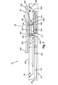
- the infeed shuttle assembly 50 (Figs. 4 and 5) includes a platform assembly 80 which can be raised to lift an empty container 24 off of the roller conveyor segments 74 and 76. Once an empty container 24 has been lifted off of the conveyor assembly 78 by the platform assembly 80, the empty container is supported by the infeed shuttle assembly 50 and is free to move with the infeed shuttle assembly.
- the infeed shuttle assembly is operable from the retracted condition shown in Fig. 4 to an extended condition in which the platform assembly 80 is in an overlapping relationship with the carriage assembly 52. At this time, the carriage assembly 52 will be at a left (as viewed in Fig. 6) end of stroke position, indicated in dashed lines in Fig. 6. When the carriage assembly 52 is at the left end of stroke position, the carriage assembly engages the left carriage stops 84 and 86 to limit leftward movement of the carriage assembly 52.
- the infeed shuttle assembly 50 When the carriage assembly 52 is at the left end of stroke position, indicated in dashed lines in Fig. 6, the infeed shuttle assembly 50 is movable to an extended condition in which the carriage assembly and the infeed shuttle assembly are in an overlapping relationship.
- the shuttle platform assembly 80 (Figs. 4 and 5) is lowered to transfer an empty container 24 from the infeed shuttle assembly 50 to the carriage assembly 52.
- the infeed shuttle assembly 50 is moved out of the overlapping relationship with the carriage assembly 52 and back to the retracted condition shown in Fig. 4.
- the infeed shuttle assembly 50 is offset to the left (as viewed in Fig. 2) of the carriage assembly 52 even though the carriage assembly is at its leftward end of stroke position in engagement with the stops 84 and 86.
- the empty container 24 (Fig. 1) is transferred to the carriage assembly 52 with the first compartment 36 of the container at the loading station 34.
- a container compartment on the right half of the carriage assembly is at the loading station 34.
- a stack 30 of signatures 22 is moved into the first compartment 36 of the container 24 while the compartment is at the loading station 34.
- the carriage assembly 52 is moved along a linear path from the left end of stroke position shown in dashed lines in Fig. 6 to the right end of stroke position, shown in solid lines in Fig. 6.
- the carriage assembly engages stops 88 and 90.
- the carriage assembly 52 is at the right end of stroke position, the second compartment 38 of the container 24 is at the loading station 34.
- a container compartment on the left half of the carriage assembly is at the loading station 34. Operation of the loader or stacker assembly 28 moves a stack 30 of signatures 22 into the second compartment 38 of the container 24.
- the container 24 After the two compartments 36 and 38 of the container 24 have been filled with signatures, the container 24 must be rotated to position the remaining two compartments, that is the compartments 40 and 42, adjacent to the loader assembly 28.
- a container support section or turntable 94 of the carriage assembly 52 is rotated through 180° relative to a base or lower section 96 of the carriage assembly 52 (Fig. 6).
- the turntable Before the turntable or upper section 94 of the carriage assembly 52 can be rotated relative to the base or lower section 96 of the carriage assembly, the turntable must be moved away from the loader assembly 28 to provide clearance between the turntable and the loader assembly as the turn table rotates.
- the turntable is mounted on a cross slide or intermediate section 98 (Figs. 6 and 7).
- the intermediate section 98 is movable along a path which is perpendicular to the path along which the carriage assembly 52 and shuttle assemblies 50 and 54 are reciprocated. By moving the intermediate section 98 outwardly, the turntable 94 is moved from the position shown in solid lines to the position shown in dash-dot lines in Fig. 6.
- the turntable 94 can be rotated through 180° about its vertical central axis.
- the 180° rotation of the turntable 94 moves the previously filled compartments 36 and 38 away from the loader assembly 28 and moves the empty compartments 40 and 42 toward the loader assembly 28.
- the intermediate section 98 of the carriage assembly 52 is then moved inwardly to the position shown in solid lines in Fig. 6. This positions the empty compartments 40 and 42 of the container 24 adjacent to the loader assembly 28 in the manner shown in Fig. 1.
- the empty compartment 40 is filled before the empty compartment 42. Therefore, the carriage assembly 52 is also moved leftwardly from the position shown in solid lines in Fig. 6 to the position shown in dashed lines in Fig. 6. When the carriage assembly has been moved to the dashed line position shown in Fig. 6, the base section 96 of the carriage assembly engages the left stop 84. At this time, the empty container compartment 40 is positioned at the loading station 34. Therefore, operation of the loader assembly 28 is effective to move a stack 30 of signatures or sheet material articles 22 into the compartment 40.
- the carriage assembly 52 is moved rightwardly from the position indicated in dashed lines to the position indicated in solid lines in Fig. 6. This movement of the carriage assembly 52 positions the last compartment 42 of the container 24 at the loading station 34, as shown in Fig. 1. Operation of the loader assembly 28 is then effective to move a stack 30 of signatures into the compartment 42.
- the compartments could be filled in any desired order. For example, the compartments 38 and 42 could be filled before the compartments 36 and 40 if desired.
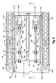
- the right or outfeed shuttle assembly 54 is extended. As the outfeed shuttle assembly 54 is extended, the carriage assembly 52 and shuttle assembly 54 move into an overlapping relationship relative to each other. When the outfeed shuttle assembly 54 is in the extended condition and the carriage assembly 52 is in the rightward position shown in solid lines in Fig. 6, a platform assembly 102 (Fig. 9) of the outfeed shuttle assembly 54 is disposed beneath the container supported on the carriage assembly 52. It should be noted that the platform assembly 102 has been removed from the outfeed shuttle assembly 54 in Figs. 2 and 8 in order to expose motors connected with the platform assembly.
- the platform assembly 102 (Fig. 9) on the outfeed shuttle assembly 54 is raised. Raising the platform assembly 102 lifts the filled container 24 off of the turntable 94 (Figs. 6 and 7). The outfeed shuttle assembly 54 is then moved back to the retracted position shown in Fig. 9 to move the outfeed shuttle assembly 54 out of the overlapping relationship with the carriage assembly 52.
- the filled container 24 is disposed over lower conveyor segments 106 and 108 (Figs. 2 and 8).
- the platform assembly 102 (Fig. 9) of the outfeed shuttle assembly 54 is then lowered. This transfers the filled container 24 from the outfeed shuttle assembly 54 to the roller conveyor segments 106 and 108 (Fig. 8).
- the filled container 24 can be moved off of the roller conveyor segments 106 and 108 by a suitable conveyor assembly 110 and conveyed to a remote storage location.
- the infeed and outfeed shuttle assemblies 50 and 54 have the same construction and mode of operation.
- the infeed shuttle assembly 50 is movable from the retracted condition shown in Fig. 1 to an extended condition in which it is disposed in an overlapping relationship with the carriage assembly 52 when the carriage assembly 52 is at the left (as viewed in Fig. 1) end of stroke position in engagement with the stops 84 and 86.
- the outfeed shuttle assembly 54 is movable from the retracted condition shown in Fig. 1 to an extended condition in which it is disposed in an overlapping relationship with the carriage assembly 52 when the carriage assembly is at a right end of stroke position (Fig. 1) in engagement with the stops 88 and 90 (Fig. 2).
- the outfeed shuttle assembly 54 includes a lift assembly 112 (Fig. 8) which is operable to move the platform assembly 102 (Fig. 9) between the lowered position shown in Fig. 9 and a raised position.
- the platform assembly 102 includes an inner or base section 116 (Figs. 9, 10 and 11) which is fixedly connected with a generally U-shaped shuttle base section or frame 118 (Fig. 8).
- the shuttle base section or frame 118 includes a pair of parallel side plates 120 and 122 (Fig. 8) which are interconnected by an end plate 124.
- the side plates 120 and 122 are each provided with longitudinally extending slots 128 (Fig. 9) which receive the carriage assembly 52 when the outfeed shuttle assembly 54 and carriage assembly are in an overlapping relationship (Fig. 10).
- Movement of the shuttle assembly 54 between the retracted and extended conditions is guided by a pair of linear tracks 132 and 134 (Figs. 8 and 9) which are fixedly connected with parallel inner side plates 136 and 138 of the main frame 70 (Figs. 8 and 9).
- the tracks 132 and 134 also guide movement of the infeed shuttle assembly 50 between the extended and retracted positions. Therefore, the infeed shuttle assembly 50 and outfeed shuttle assembly 54 reciprocate along the same linear path relative to the main frame 70 of the container handling assembly 46.
- a shuttle motor assembly 146 (Figs. 8 and 9) is operable to move the base frame 118 of the outfeed shuttle assembly 54 from the retracted position shown in Fig. 8 to an extended position in which the shuttle assembly 54 is disposed in an overlapping relationship with the carriage assembly 52.
- stop bolts 148 and 150 on the ends of the side plates 120 and 122 (Fig. 8) are disposed in abutting engagement with shuttle assembly stops 152 and 154 (Fig. 6).
- the infeed shuttle assembly 50 is in the extended position, the base frame of the shuttle assembly engages the stops 152 and 154.
- the shuttle motor assembly 146 (Fig. 9) includes an upper motor cylinder 158.
- the upper motor cylinder 158 is slidably mounted on a lower motor cylinder 160 by a guide track 162.
- the piston rod 166 of the upper motor cylinder 158 is fixedly connected to the platform assembly 102 (Fig. 9) by a block 168.
- the lower motor cylinder 160 is fixedly connected with an end plate 172 of the main frame 70 and extends parallel to the upper motor cylinder 158.
- the piston rod 176 of the lower motor cylinder 160 is connected with the upper motor cylinder 158 by a connector section 178.
- the piston rod 176 Upon operation of the lower motor cylinder 160 from the retracted condition shown in Fig. 9 to the extended condition, the piston rod 176 is extended toward the left. Leftward (as viewed in Fig. 9) movement of the piston rod 176 moves the upper motor cylinder 158 and the platform assembly 102 toward the left. Operation of the upper motor cylinder 158 from the retracted condition shown in Fig. 9 to the extended condition moves the piston rod 166 toward the left. This moves the platform assembly 102 leftwardly relative to both the upper motor cylinder 158 and the lower motor cylinder 160. Therefore, the platform assembly 102 is moved leftwardly from a retracted position to an extended position through a distance which equals the combined operating strokes of the upper and lower motor cylinders 158 and 160.
- the base frame 118 of the platform assembly 54 moves leftwardly until the stops 148 and 150 (Fig. 8) on the leading ends of the base section 118 engage the shuttle assembly stops 152 and 154 (Fig. 6).
- the outfeed shuttle assembly 54 is in the extended position and the carriage 52 is in the rightward position shown in solid lines in Fig. 6, the outfeed shuttle assembly 54 and carriage 52 are in an overlapping relationship.
- the carriage assembly 52 extends through slots 128 (Fig. 9) in the opposite side plates 120 and 122 of the shuttle assembly base frame 118.
- the turntable 94, intermediate section 98 and base section 96 (Fig. 10) of the shuttle assembly 52 extend through the slots 128 in the side plate 120 of the shuttle base frame 118.
- the platform assembly 102 is disposed above the carriage assembly 52.
- the carriage assembly 52 could be disposed above the platform assembly 102 and when the carriage assembly and shuttle assembly 54 are in an overlapping relationship.
- the turntable 94 could be disposed above the platform assembly 102 when the carriage assembly 52 and shuttle assembly 54 are in an overlapping relationship.
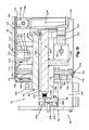
- the platform lift assembly 112 (Fig. 8) is operable to move an upper or container support section 184 of the platform assembly 102 upwardly relative to the base or inner support section 116 (Figs. 9, 10 and 11).
- the platform lift assembly 112 includes a pair of lift motors 188 and 190 (Fig. 8).
- the lift motors 188 and 190 are fixedly connected with the inner or base section 116 (Figs. 9 and 11) of the platform assembly 102.
- the lift motors 188 and 190 are operable to actuate toggle lift assemblies 194 and 196 (Figs. 8, 10 and 11) to raise the container support section 184 (Figs. 10 and 11) of the platform assembly 102 relative to the base section 116 of the platform assembly.
- the toggle lift assembly 194 includes a pair of toggle arms 200 and 202 (Fig. 8).
- a pair of rollers 204 and 206 (Figs. 8, 10 and 11) are mounted on upper end portions of the toggle arms 200 and 202.
- the toggle arms 200 and 202 are pivotally mounted on and movable with the base section 116 of the platform assembly 102 relative to the frame 70 upon operation of the shuttle assembly motor 146.
- the toggle arm 202 is pivotally mounted on a support pin 210 (Fig. 11).
- the support pin 210 is connected with the base section 116 by a pair of mounting brackets 212 and 214 (Fig. 10).
- An actuator bar 218 (Figs. 8, 10 and 11) is pivotally connected to the lower end portions of the toggle arms 200 and 202.
- the toggle actuator bar 218 When the toggle motor 188 is operated from the retracted condition shown in Figs. 8 and 11, the toggle actuator bar 218 is moved toward the left. Leftward movement of the toggle actuator bar 218 pivots the toggle arms 200 and 202. Pivoting the toggle arms 200 and 202 raises the rollers 204 and 206 through openings 222 (Figs. 10 and 11) formed in the base section 116 of the platform assembly 102. Upward movement of the rollers 204 and 206 raises the container support section 184 of the platform assembly 102 upwardly relative to the base section.
- the roller 206 (Figs. 10 and 11) moves upwardly through the opening 222 formed in the base section 116 and engages the upper or container support section 184 of the platform assembly 122 during initial movement of the actuator bar 218.
- Continued movement of the actuator bar 218 causes the toggle arm 202 to continue to pivot in a clockwise direction (as viewed in Fig. 11) about the support pin 210 to lift the upper section 184 of the platform assembly 102 upwardly away from the lower or base section 116 of the platform assembly.
- a guide block 228 connected with the container support section 184 (Fig. 10) is engaged by a pair of guide blocks connected with the inner support section 116 to guide upward movement of the container support section relative to the base section 116 of the platform assembly 102.
- a single guide block 228 has been shown in Fig. 10, it should be understood that there are four guide blocks provided adjacent to the corners of the container support section 184. These four guide blocks cooperate with four pairs of guide blocks connected with the base section 116 adjacent to the corner portions of the base section.
- the actuator bar 218 When the toggle motor 188 is retracted, the actuator bar 218 is moved toward the right (as viewed in Fig. 8). This results in the toggle arm 222 pivoting in a counterclockwise direction (as viewed in Fig. 11) to move the toggle arm 202 from the raised position to the lowered position.
- the toggle arm 200 is pivoted in the same manner as the toggle arm 202 when the toggle motor 188 is retracted.
- the toggle arms 200 and 202 As the toggle arms 200 and 202 are pivoted downwardly, the upper or container support section 184 of the platform assembly 102 moves downwardly into abutting engagement with the base section 116 of the platform assembly.
- toggle linkage assembly 194 associated with the motor 188
- a similar toggle linkage 196 is associated with the motor 190 (Fig. 8).
- a tie rod or bar 226 extends between the two toggle linkage arrangements and interconnects them.
- the toggle motors 188 and 190 are simultaneously actuated to operate the toggle linkages 194 and 196 at the same time.
- the infeed shuttle assembly 50 includes a motor having the same construction as the shuttle motor 146. This motor is operable to move the infeed shuttle assembly 50 between the retracted position shown in Figs. 1 and 2 and an extended position in which the infeed shuttle assembly is in an overlapping relationship with the carriage assembly 52.
- the infeed shuttle assembly 50 also includes a lift assembly having the same construction as the lift assembly 112.
- the lift assembly in the infeed shuttle assembly 50 is operable to move an upper container support section of the platform assembly 80 relative to an inner or base section of the platform assembly 80. This is done in the same manner as in which the container support section 184 of the platform assembly 102 is moved relative to the base or inner section 116 of the platform assembly. Since the shuttle assemblies 50 and 54 have the same construction and mode of operation, either shuttle assembly can be used as the infeed shuttle assembly while the other shuttle assembly is used as the outfeed shuttle assembly.
- the carriage assembly 52 is operable to move a container 24 along a linear path and to rotate the container about a vertical axis which extends through the center of the container.
- the carriage assembly 52 (Fig. 6) includes the base section 96, the intermediate section 98 and a turntable 94 which is rotatably mounted on the intermediate section 98 (Fig. 7).
- the base section 96 (Fig. 6) is movable along linear guide tracks 236 and 238 connected with a pair of outer side plates 240 and 242 of the main frame 70.
- the inner side plates 136 and 138 are connected in a parallel relationship with the outer side plates 240 and 242 by spreader plates 244.
- the base section 96 of the carriage assembly 52 includes a pair of parallel end plates 248 and 250 which are supported by rollers 252 (Figs. 6 and 10) for movement along the tracks 236 and 238.
- a pair of parallel cross plates 256 and 258 (Figs. 6, 7, 10 and 11) extend perpendicular to and interconnect the side plates 248 and 250.
- the cross plates 256 and 258 support the intermediate section 98 (Figs. 6 and 7) for movement along a path extending perpendicular to the side plates 248 and 250 and the carriage tracks 236 and 238.
- the intermediate section 98 has a rectangular body portion 260 (Figs. 7, 10 and 11).
- the body portion 260 of the intermediate section 98 is supported for movement along tracks 262 and 264 (Figs. 7 and 11) formed in the cross plates 256 and 258 of the base section 96 by rollers 266.
- a stop 270 (Fig. 6) connected to the side plate 248 limits movement of the intermediate section 98 toward the side plate 248.
- a second stop limits movement of the intermediate section 98 toward the side plate 250 when the turntable 94 has moved to the position shown in dash-dot lines in Fig. 6.
- movement of the intermediate section 98 in a direction perpendicular to the path of movement of the carriage assembly 52 along the tracks 236 and 238 is effective to move the turn table 94 from an inner position (shown in solid lines in Fig. 6) to an outer position (shown in dash-dot lines in Fig. 6) to provide space for the turntable 94 to rotate about its central axis.
- the turntable 94 is rotatably supported on the intermediate section 98 by a cylindrical post 274 (Figs. 6, 7, 10 and 11).
- the turntable 94 has a generally H-shaped configuration (Fig. 6) with the support post 274 extending through a center cross section 278 of the turntable 94.
- a pair of elongated parallel support sections 280 and 282 extend perpendicular to and are fixedly connected with the center cross section 278.
- Container positioning pads 284 are disposed at the four corners of the turntable 94 to engage recesses in the containers 24 to position the containers relative to the turntable.
- a carriage motor 290 (Figs. 4 and 5) includes a cylinder 292 which is fixedly connected to the main frame 70 (Fig. 4).
- the motor 290 includes a piston rod 294 (Figs. 4, 6 and 7) which extends from the cylinder 292 to the base section 96 (Figs. 6 and 7) of the carriage assembly 52.
- the piston rod 294 is connected to the cross plate 256 of the carriage base section 96.
- the carriage assembly 52 When the carriage motor 290 is in the extended condition shown in Figs. 4 and 6, the carriage assembly 52 is at a right (as viewed in Fig. 6) end of stroke position in which the base section 96 engages the carriage stops 88 and 90. At this time, the left (as viewed in Fig. 6) half of the turntable 94 is disposed at the loading station 34.
- the carriage assembly Upon operation of the carriage motor 290 toward a retracted condition, the carriage assembly is moved along the tracks 236 and 238 to a left end of stroke position indicated in dashed lines in Fig. 6. At this time, the right (as viewed in Fig. 6) half of the turntable 94 is disposed at the loading station 34.
- An empty container 24 is initially placed on the carriage assembly 52 when the carriage assembly is at the left end of stroke position, that is when the base section 96 is in engagement with the carriage stops 84 and 86 (Fig. 6). At this time, the first compartment 36 (Fig. 1) in the empty container is disposed at the loading station 34. Upon operation of the carriage motor 290 to the extended condition, the carriage assembly 52 is moved to the right end of stroke position, shown in solid lines in Fig. 6. At this time, the base section 96 of the carriage assembly 52 is disposed in engagement with the carriage stops 88 and 90 and the compartment 38 of the container 24 is disposed at the loading station 34.
- the container 24 is rotated about its vertical central axis. This is accomplished by rotating the turntable or container support section 94 of the carriage assembly 52 about the vertical central axis of the post 274.
- the intermediate section 98 of the carriage assembly 52 is moved away from the loader assembly 28 to provide room for the turntable 94 to rotate. This is accomplished by operating an intermediate section motor 300 (Fig. 6) to move the intermediate section 98 relative to the base section 96 of the carriage assembly 52.
- the intermediate section motor 300 includes a cylinder 302 which is fixedly connected to the side plate 250 of the carriage base section 96.
- a piston rod 304 of the intermediate section motor 300 is fixedly connected to a support plate 306 (Fig. 6) which is secured to the intermediate section 98.
- the intermediate section motor 300 Since the intermediate section motor 300 is connected with the intermediate section 98 and the base section 96, operation of the intermediate section motor moves the intermediate section 98 relative to the base section. Thus, when the intermediate section motor 300 is operated from the extended condition shown in Fig. 6 to a retracted condition, the piston rod 304 pulls the intermediate section 98 toward the side plate 250 of the base section 96. This moves the turntable 94 from the loading position shown in solid lines shown in Fig. 6 to the index position shown in dashed-dot lines.
- a turntable motor 310 is operated to move a rack gear 312 to rotate a pinion gear 314 (Figs. 6, 7, 10 and 11).
- the turntable motor 310 includes a movable cylinder 318 (Fig. 6) which is fixedly connected with the rack gear 312.
- the cylinder 318 is movable relative to a piston rod 320 which is fixedly connected at opposite ends with the support plate 306.
- the cylinder 318 moves leftwardly from the position shown in Fig. 6 to a position adjacent to the opposite end of the piston rod 320. This movement of the cylinder 318 and rack gear 312 rotates the pinion gear 314 and turntable 94 in a counterclockwise direction (as viewed in Fig. 6).
- the rack gear 312 is moved from left to right (as viewed in Fig. 6) to rotate the pinion gear 314 and turntable 94 in a clockwise direction.
- the turntable motor 310 is of the type in which a cylinder moves relative to a piston and piston rod during operation of the motor. If desired, the motor could be constructed so as to have the rack gear 312 connected with a piston rod which moves relative to a cylinder. In fact, it is contemplated that a pair of motors could be connected with the rack gear 312. If this was done, both of the motors would be operated simultaneously to effect rotation of the pinion gear 314.
- the loader or stacker assembly 28 (Fig. 12) is provided with a plurality of platforms 224 which are mounted on an endless chain mechanism 226 trained around upper and lower sprockets 228 and 230.
- the chain mechanism 226 is positioned along an inclined front face 234 of the loader assembly 28 so that successive platforms 224 intercept signatures 22 from a signature conveyor 238. Operation of the chain mechanism 226 is timed to move the platforms 224 downwardly along the face 234 of the loader or stacker assembly 28 at the same rate at which the stack 30 of signatures on the upper front platform 224 grows. This keeps the top of the growing stack 30 of signatures at an intercept position registered with the conveyor assembly 238.
- platforms 224 are shown attached to the chain 226, there are, in reality, several more, for instance three additional platforms, the exact number being a function of the stack height desired, the size of equipment and speed of operation of the system components.
- the spacing between platforms is the amount necessary to allow one stack to be built before interception of the flow of signatures by a following platform and start of a new stack.
- a counter is arranged to count the number of signatures deposited on a platform 224. Interception of the flow of signatures from the conveyor 238 (Fig. 12) by each platform 224 is initiated when a predetermined desired number of signatures are positioned on the preceding platform.
- the chain mechanism 226 is comprised of a pair of co-extensive chains, and alternate platforms 224 are mounted on one chain or the other.
- the chains are independently movable. As one platform 224 is being loaded, the chain for the next platform is advanced so that this platform is poised for interception of the stream of signatures 22 from the conveyor assembly 238 when loading of the preceding platform is completed. Rapid activation of an intercepting platform 224 is achieved by pivotally mounting the platform on the respective chains.
- the platforms in the poised position are held in a raised spring-loaded mode by a latch which is adapted to release the platforms to the intercepting mode when loading of the preceding platform is completed. In this way, the continuous movement of the signatures can be maintained without interruption.
- the chain mechanism 226 and associated platforms 224 are substantially co-extensive with the inclined face 234 of the stacker assembly 28.
- a second chain mechanism 244 is provided below the chain mechanism 226.
- the second chain mechanism 244 is substantially co-extensive with a vertical lower face 246 of the stacker assembly 28.
- This chain mechanism is trained around a lower sprocket 248 and an upper sprocket (not shown) which is coaxial with and spaced from the sprocket 230.
- the fork 254 (Fig. 12) is adapted to be moved in and out from the face of the stacker assembly 28 in the direction of the arrows 256.
- the fork 254 is moved in and out by an actuator 260 which is moved up an down in the direction of the arrows 262 by the chain mechanism 244.
- the chain mechanism 244 is driven by reversible motors 266 and 268 coupled to the chain mechanism 244 through clutch and brake mechanisms 272 and 274.
- the motor 266 is operable to effect movement of the fork 254 downwardly at a first speed, which is greater than the speed of downward movement of the platforms 224 and stack 30.
- the motor 268 effects upward movement of the fork 254 after the fork has been retracted to deposit a stack 30 of signatures in a container, at a speed which is greater than the speed at which the fork 254 is moved downwardly.
- the fork 254 is initially positioned at its uppermost point of travel which is adapted to be slightly above the lowermost point of travel of the platforms 224.
- the platforms 224 are configured to mesh with and pass by the fork 254 in their downward travel so that a stack of signatures on a platform 224 is transferred from the platform to the fork 254.
- the fork 254, upon receipt of stack of signatures, is lowered to its lowermost position, by the motor 266.
- the stack 30 of signatures is reposed on an incline against the upper face 234 when transferred to the fork 254.
- the stack 30 is deflected into vertical repose by means of a deflecting surface at the point of juncture between the inclined face 234 and vertical face 246 of the stacker loader assembly 228.
- the loader fork 254 and stack 30 enter an empty compartment in a container 24 through the open upper end of the compartment.
- the stack 30 moves vertically downwardly in a compartment of the container 24.
- the stack is supported by the loader fork 254 which extends through a vertical slot or opening in one side of the compartment.
- the fork 254 is withdrawn inwardly by the actuator 260 to a position in which the fork 254 is clear of the stack 30 and the container.
- the fork 254 is withdrawn to a position in which it is to the right (as viewed in Fig. 12) of the vertical side surface 246 of the loader assembly 28.
- Each of the containers 24 (Fig. 1) includes four compartments 36, 38, 40 and 42 disposed in a rectangular array.
- the compartments 36 and 38 share a common vertical inner side wall 282.
- the compartments 38 and 40 share a common vertical inner wall 284.
- the compartments 40 and 42 share a common vertical inner wall 288.
- the compartments 36 and 42 share a common vertical inner wall 290.
- the inner walls 282, 284, 288 and 290 intersect to form an X having its center at the center of the container 24.
- the compartments 36 and 38 (Fig. 1) have elongated vertically extending openings 294 and 296 which face in the same direction and are disposed on one side of the container 24.
- the compartments 40 and 42 have elongated vertically extending openings 298 and 300 which face in the opposite direction from the openings 294 and 296 and are disposed on the opposite side of the container 24.
- a pair of major outer side walls 304 and 306 form outer side walls of the compartments.
- the wall 304 forms an outer side wall of the compartments 36 and 42 while the outer wall 306 forms a side wall of the compartments 38 and 40.
- a pair of planar or flange wall sections 308 and 310 extend inwardly on opposite vertical edge portions of the outer side wall 304 to partially define the openings 294 and 300 in opposite sides of the container.
- a second pair of flange or minor wall sections 312 and 314 extend from opposite edge portions of the major wall 306 to partially define the openings 296 and 298.
- a pair of central secondary or minor side walls 318 and 320 extend from opposite sides of the inner walls 282 and 288 to further define the openings 294, 296, 298 and 300.
- the loader fork 254 moves vertically downwardly through each of the openings 294, 296, 298 and 300 (Fig. 1) in turn to lower a stack of sheet material articles into a compartment of the container. Slots are provided in the lower end portions of the container 24 to receive the fork 254 during loading of a stack of sheet material articles into a compartment. Since the containers 24 are symmetrical on opposite sides of the inner walls 284 and 290, the containers can be positioned in the orientation shown in Fig. 1 or in an orientation offset 180° from the orientation shown in Fig. 1. However, regardless of the orientation of the containers, the compartment disposed where the compartment 36 is shown in Fig. 1 is filled first and the compartment disposed where the compartment 42 is shown in Fig. 1 is filled last.
- Controls 324 (Fig. 13) for the container handling assembly 46 include valves for controlling the operation of the various motors in the container handling assembly.
- a control valve 328 (Fig. 13) is operable to effect simultaneous raising or lowering of the platform assemblies 80 and 102 (Figs. 5 and 9) in the shuttle assemblies 50 and 54.
- the control valve 328 When the control valve 328 is in the position shown in Fig. 13, the platform assemblies 80 and 102 are in their lowered condition.
- the right container support section lift motors 188 and 190 (Fig. 8) are in the illustrated retracted condition.
- left container support section lift motors 330 and 332 (Fig. 13) are in their retracted condition.
- a control valve 336 is actuatable to effect movement of the left or infeed shuttle assembly 50 (Figs. 1, 2 and 4) between the retracted and extended conditions.
- the left shuttle assembly 50 When the control valve 336 is in the position shown in Fig. 13, the left shuttle assembly 50 is retracted.
- upper and lower cylinders 338 and 340 of a left shuttle assembly motor 342 are retracted.
- the upper and lower cylinders 338 and 340 of the left shuttle motor 342 are extended to move the left shuttle assembly 50.
- the left shuttle assembly 50 is moved from the retracted condition shown in Figs. 1 and 2 to an extended condition in which the left shuttle assembly is disposed in an overlapping relationship with the carriage assembly 52.
- the left shuttle assembly motor 342 has the same construction as the right shuttle assembly motor 146 (Fig. 9).
- valve 346 When the valve 346 is in the condition shown in Fig. 13, the right shuttle motor assembly 146 is extended so that the right shuttle assembly 54 is in an overlapping relationship with the carriage assembly 52.
- the upper motor cylinder 158 and lower motor cylinder 160 (Fig. 9) are both extended as shown in Fig. 13.
- Movement of the carriage assembly 52 between its left and right end of stroke positions is controlled by the valve 350.
- the valve 350 when the valve 350 is in the position shown in Fig. 13, the carriage motor 290 is extended to move the base section 96 of the carriage assembly 52 to the position shown in solid lines in Fig. 6.
- the carriage assembly 52 When the carriage assembly 52 is in this position, either the second or the fourth compartment 38 or 42 of a container 24 can be filled with sheet material articles.
- the carriage motor 290 When the valve 350 is operated from the actuated condition shown in Fig. 13, the carriage motor 290 is retracted to move the carriage assembly 52 to the position shown in dashed lines in Fig. 6. Upon actuation of the valve 350 from the position shown in Fig. 13, the carriage motor 290 is retracted to move the carriage assembly leftward to the position shown in dashed lines in Fig. 6. When the carriage assembly 52 is in this position, either the first or the third compartments 36 or 40 of the container 24 can be filled with sheet material articles.
- Movement of the turntable 94 toward and away from the loader or stacker assembly 28 is controlled by actuation of a valve 354.
- the turntable motor 300 (Fig. 6) is extended so that the turntable 94 is in or adjacent to the loader assembly 28.
- the intermediate section motor 300 is retracted to move the turntable 94 outwardly to the position indicated in dash-dot lines in Fig. 6.
- a valve 356 is operable to rotate the turntable 94 through 180° in either a clockwise or counterclockwise direction relative to the base and intermediate sections 96 and 98 of the carriage assembly when the turntable 94 is in the out position, that is when the motor 300 is retracted. Actuation of the valve 356 from the position shown in Fig. 13 results in the turntable motor cylinder 318 and rack gear 312 (Fig. 6) being moved to rotate the turntable 94 in a clockwise direction (as viewed in Fig. 6). Upon subsequent operation of the valve 356 back to the position shown in Fig. 13, the motor 310 moves the rack gear 312 to rotate the turntable 94 in a counterclockwise direction (as viewed in Fig. 6).
- valves 328, 336, 346, 350, 354 and 356 are supplied with fluid under pressure, that is air, by a pump 360. Air is exhausted to the atmosphere through a manifold 362. Although it is preferred to use air operated motors to actuate the container handling assembly 346, hydraulic motors could be used if desired.
- FIG. 14 An operating cycle of the container handling assembly 46 is illustrated schematically in Fig. 14.
- the valves 328, 336, 346, 350, 354 and 356 are in the positions shown in Fig. 13.
- the platform assemblies 80 and 102 are both in a lowered condition and the platform lift motors 188, 190, 330 and 332 (Fig. 13) are in their retracted condition.
- the left or infeed shuttle assembly 50 is in the retracted condition shown in Figs. 1 and 4. Therefore, the upper and lower cylinders 338 and 340 of the shuttle motor assembly 342 are retracted. At this time, the platform assembly 80 of the left shuttle assembly 50 is disposed beneath an empty container 24 disposed on the roller conveyor segments 74 and 76 (Fig. 1).
- the right or outfeed shuttle assembly 54 is extended into an overlapping relationship with the carriage assembly 52.
- the upper and lower cylinders 158 and 160 of the shuttle motor assembly 146 are extended.
- the platform assembly 102 of the right shuttle assembly 54 is disposed beneath a filled or loaded container 24 disposed on the carriage assembly 52.
- the intermediate section motor 300 of the carriage assembly 52 is extended. Therefore, the carriage assembly 52 is close to the loader assembly 28, in the position in which the last or fourth compartment 42 (Fig. 1) is filled with sheet material articles 22. Finally, the turntable motor cylinder 318 is disposed to the left of the position shown in Fig. 6.
- the control valve 328 (Fig. 13) is operated to effect simultaneous raising of the platform assemblies 80 and 102 in the left and right shuttle assemblies 50 and 54, in the manner indicated by the line 370 in Fig. 14.
- the control valve 328 (Fig. 13) is actuated to port high pressure fluid to the head ends of the container support section lift motors 188, 190, 330 and 332.
- This effects a raising of the platform assembly 80 of the left shuttle assembly 50 to lift an empty container upwardly off of the infeed roller conveyor segments 74 and 76.
- the platform assembly 102 of the right shuttle assembly 54 is raised to lift a filled container upwardly off of the carriage assembly 52.
- the left shuttle assembly 50 is extended, in the manner indicated schematically by the line 374 in Fig. 14. This is accomplished by actuating the control valve 336 from the position shown in Fig. 13 to port high pressure fluid to the head ends of the motor cylinders 338 and 340.
- the right shuttle assembly 54 is being retracted. Retraction of the right shuttle assembly 54 moves a filled container from a position over the carriage assembly 52 to a position offset to one side of the carriage assembly, in the manner indicated schematically by the line 376 in Fig. 14. This is accomplished by operating the control valve 346 (Fig. 13) to port high pressure fluid to the rod ends of the motor cylinders 158 and 160. Therefore, as an empty container 24 is moved over the shuttle assembly 52, a filled container 54 is moved from the shuttle assembly 52 to a position over the outfeed roller conveyor segments 106 and 108 (Fig. 1).
- the carriage assembly 52 is moved from a right end of stroke position to a left end of stroke position.
- the valve 350 (Fig. 13) is actuated to direct high pressure fluid to the rod end of the carriage motor 290.
- the platform assemblies 80 and 102 of the shuttle assemblies 50 and 54 are lowered, in the manner indicated by the line 386 in Fig. 14. This results in the empty container 24 being transferred to the carriage assembly 52 and in the loaded container being transferred to the roller conveyor outfeed segments 106 and 108. Lowering of the platform assemblies 80 and 102 is effected by actuating the valve 328 back to the position shown in Fig. 13.
- the left shuttle assembly is retracted, in the manner indicated schematically by the line 388 in Fig. 14. Retraction of the left shuttle assembly 50 is effected by actuating the control valve 336 back to the position shown in Fig. 13.
- the loader assembly 28 is operated to load signatures or sheet material articles into the first compartment 36 of the container 24. During this time, the container handling assembly 46 remains stationary. The loader assembly 28 is operated to lower a stack 30 of signatures through the open upper end of the compartment 36. As this occurs, the loader fork 254 (Fig. 12) moves downwardly along the vertical slot or opening 294 (Fig. 1). The loader fork 254 is then withdrawn from the container 24 through the slot 294.
- the carriage assembly 52 is moved rightwardly from the first loading position to the second loading position.
- the carriage assembly 52 is moved from the position indicated in dashed lines in Fig. 6 to the position indicated in solid lines, in the manner indicated schematically by the line 392 in Fig. 14.
- Rightward movement of the carriage assembly 52 to the position shown in solid lines in Fig. 6 is effected by actuating the control valve 350 to the position shown in Fig. 13.
- the second compartment 38 of the container 24 is at the loading station 34.
- the loader assembly 28 is then operated to fill the second compartment 38 of the container 24 with a stack 30 of the sheet material articles 22.
- the loader assembly 28 moves a stack of signatures downwardly through the open upper end of the compartment 38.
- the loader fork 254 (Fig. 12) moves downwardly along the vertical slot or opening 296 (Fig. 1).
- the loader fork 254 is then withdrawn from the container 24 through the slot 296.
- the intermediate section 98 of the carriage assembly 52 is moved away from the loader assembly 28, in the manner indicated schematically by the line 394 in Fig. 14. This moves the turntable 94 from the position shown in solid lines in Fig. 6 to the position shown in dash-dot lines in Fig. 6. Movement of the intermediate section 98 away from the loader assembly 28 is effected by actuating the control valve 354 (Fig. 13) to retract the intermediate section motor 300.
- the turntable 94 is rotated, in a clockwise direction, in the manner indicated schematically by the line 396 in Fig. 14. This is accomplished by actuating the control valve 356 from the position shown in Fig. 13. As the turntable 94 is rotated through 180° about a vertical axis, the half filled container 24 is rotated from a position in which the filled compartments 36 and 38 are adjacent to the loader assembly 28 to a position in which the empty compartments 40 and 42 are adjacent to the loader assembly.
- the carriage assembly 52 is moved toward the left to align the empty compartment 40 of the container 24 with the loading station 34.
- This leftward movement of the turntable 94 is indicated schematically by the line 400 in Fig. 14.
- Leftward movement of the turntable 94 is effected by actuating the valve 350 to port high pressure fluid to the rod end of the carriage motor 290.
- the intermediate section 98 of the carriage assembly 52 is moved toward the loader assembly 28 to position the empty compartment 40 at the loading station 34.
- This inward movement of the intermediate section 98 of the carriage assembly is indicated schematically by the line 402 in Fig. 14.
- Inward movement of the intermediate section 98 of the carriage assembly 52 is effected by actuating the control valve 354 to port high pressure fluid to the head end of the intermediate section motor 300.
- the compartment 40 of the container 24 is disposed at the loading station 34.
- the loader assembly 28 is then operated to lower a stack of signatures through the open upper end of the empty compartment 40.
- the loader fork 254 (Fig. 12) moves downwardly along the vertical slot or opening 298 (Fig. 1).
- the loader fork 254 is then withdrawn from the container 24 through the slot 298.
- the carriage assembly 52 is moved from the position shown in dashed lines in Fig. 6 to the position shown in solid lines in Fig. 6. This moves the compartment 42 to the loading station 34. Movement of the carriage assembly 52 to the position shown in solid lines in Fig. 6 is indicated by the line 404 in Fig. 14. Movement of the carriage assembly 52 to the position shown in solid lines in Fig. 6 is effected by actuating the control valve 350 to the position shown in Fig. 13. This ports high pressure fluid to the head end of the carriage motor 290 to extend the carriage motor.
- the lowered right shuttle assembly 54 is extended into an overlapping relationship with the carriage assembly. This movement of the right shuttle assembly is indicated by the line 406 in Fig. 14. Operation of the right shuttle assembly 54 to the extended condition is effected by actuating the control valve 346 to the condition shown in Fig. 13. This ports high pressure fluid to the head ends of the motor cylinders 158 and 160.
- the compartment is filled with a stack 30 of sheet material articles by the loader assembly 28.
- the loader assembly 28 moves a stack of signatures downwardly through the open upper end of the compartment 42.
- the loader fork 254 (Fig. 12) moves downwardly along the vertical slot or opening 300 (Fig. 1).
- the loader fork 254 is then withdrawn from the container 24 through the slot 300.
- the operating cycle is then repeated to move the loaded container 24 off of the carriage assembly 52 and to move the next succeeding container onto the carriage assembly.
- the container handling assembly 46 is then operated to fill the empty compartments of this empty container in the manner previously explained.
- a single loader or stacker assembly 28 is provided in association with a single container handling assembly 46 to sequentially load sheet material articles into a plurality of compartments in each of a plurality of containers 24.
- a plurality of loader or stacker assemblies are associated with a plurality of container handling assemblies to sequentially load sheet material articles to a plurality of containers. Since the apparatus illustrated in Fig. 15 is generally similar to the apparatus illustrated in Figs. 1-14, similar numerals will be utilized to designate similar components, the suffix letter "a" being associated with the numerals of Fig. 15 to avoid confusion.
- the apparatus 20a for sequentially loading sheet material articles into a plurality of compartments 36a, 38a, 40a, and 42a of a container 24a includes a pair of loader or stacker assemblies 28a.
- a pair of container handling assemblies 46a have the same construction and mode of operation as the container handling assembly 46 of Figs. 1-14.
- An empty container infeed conveyor 412 is operable to move empty containers 24a to each of the loader assemblies 28a in turn.
- An outfeed conveyor assembly 414 is provided to move the filled containers 24a away from the container handling apparatus 46a.
- loader assemblies 28a Although only a pair of loader assemblies 28a have been shown in association with infeed and outfeed conveyors 412 and 414 in Fig. 15, it should be understood that as many loader assemblies 28a as desired could be provided. Of course, a separate container handling assembly 46a would be associated with each of the loader assemblies 28a. Although one particular relationship between the infeed conveyor 412 and outfeed conveyor 414 and the container handling assemblies 46a has been shown in Fig. 15, it should be understood that any desired arrangement of loader assemblies 28a and container handling assemblies 46a could be provided to sequentially load containers 24a with sheet material articles.
- the present invention provides a new and improved apparatus 20 and method for sequentially loading sheet material articles 22 into a plurality of compartments 36, 38, 40 and 42 in each of a plurality of containers 24.
- the container is moved to a first or infeed shuttle assembly 50.
- the empty container 24 is transferred from the infeed shuttle assembly 50 to a carriage assembly 52.
- the transfer of the empty container from the infeed shuttle assembly 50 to the carriage assembly 52 may be accomplished by moving the shuttle assembly and carriage assembly into an overlapping relationship.
- the infeed shuttle assembly 50 and carriage assembly 52 may then be moved vertically relative to each other to transfer the empty container 24 from the shuttle assembly to the carriage assembly.
- each of the compartments 36, 38, 40 and 42 in the empty container is filled in turn with sheet material articles 22 while the container is supported by the carriage assembly.
- the carriage assembly 52 is movable relative to a loader or stacker assembly 28 to sequentially position the compartments of the container 24 at a loading station 34.
- the carriage assembly 52 may advantageously be operated to move the empty container along a linear path and to rotate the container about a vertical axis.
- the container 24 is transferred from the carriage assembly 52 to a second or outfeed shuttle assembly 54. This may be accomplished by moving the outfeed shuttle assembly 54 into an overlapping relationship with the carriage assembly 52 and providing relative vertical movement between the loaded container 24 and the outfeed shuttle assembly. The carriage assembly 52 and outfeed shuttle assembly 54 are then moved out of the overlapping relationship with each other while the container 24 is supported by the outfeed shuttle assembly.
Landscapes
- Engineering & Computer Science (AREA)
- Mechanical Engineering (AREA)
- Chemical & Material Sciences (AREA)
- Combustion & Propulsion (AREA)
- Transportation (AREA)
- Specific Conveyance Elements (AREA)
- Auxiliary Devices For And Details Of Packaging Control (AREA)
- Reciprocating Conveyors (AREA)
Applications Claiming Priority (2)
| Application Number | Priority Date | Filing Date | Title |
|---|---|---|---|
| US07/566,616 US5069598A (en) | 1988-10-24 | 1990-08-13 | Apparatus and method for loading sheet material articles |
| US566616 | 1990-08-13 |
Publications (2)
| Publication Number | Publication Date |
|---|---|
| EP0472816A1 true EP0472816A1 (fr) | 1992-03-04 |
| EP0472816B1 EP0472816B1 (fr) | 1995-09-20 |
Family
ID=24263638
Family Applications (1)
| Application Number | Title | Priority Date | Filing Date |
|---|---|---|---|
| EP91107303A Expired - Lifetime EP0472816B1 (fr) | 1990-08-13 | 1991-07-08 | Appareil et méthode de chargement de matériaux en forme de feuille |
Country Status (3)
| Country | Link |
|---|---|
| US (1) | US5069598A (fr) |
| EP (1) | EP0472816B1 (fr) |
| DE (1) | DE69113180T2 (fr) |
Cited By (2)
| Publication number | Priority date | Publication date | Assignee | Title |
|---|---|---|---|---|
| WO2001081219A1 (fr) * | 2000-04-20 | 2001-11-01 | Böwe Systec AG | Procede et dispositif pour former des groupes de feuilles comprenant une ou plusieurs feuilles |
| EP2128065A3 (fr) * | 2008-05-29 | 2010-06-02 | BHS Corrugated Maschinen-und Anlagenbau GmbH | Dispositif d'empilage |
Families Citing this family (18)
| Publication number | Priority date | Publication date | Assignee | Title |
|---|---|---|---|---|
| US5171125A (en) * | 1988-10-24 | 1992-12-15 | Am International Incorporated | Sheet material handling apparatus and method having a pivotable hopper and bottom feeder |
| US5263701A (en) * | 1988-10-24 | 1993-11-23 | Am International Incorporated | Collapsable container for stacks of sheet material |
| US5219158A (en) * | 1992-09-28 | 1993-06-15 | Xerox Corporation | Two corner sheet stacking apparatus with matching cover |
| DE59408112D1 (de) * | 1993-10-27 | 1999-05-20 | Grapha Holding Ag | Verfahren und Behälter zum Versand von Druckereierzeugnissen |
| US6099452A (en) * | 1995-03-01 | 2000-08-08 | Moore Business Forms, Inc. | Forms stacker |
| US6234467B1 (en) * | 1997-11-10 | 2001-05-22 | Kurt Runzi | Apparatus for stacking and sorting printed documents and feeding them to a finishing machine |
| DE19820805B4 (de) * | 1998-05-09 | 2004-04-08 | Skinetta Pac-Systeme Kiener Gmbh & Co. | Abstapelvorrichtung |
| US6301776B1 (en) | 1998-05-15 | 2001-10-16 | Samsung Electronics Co., Ltd. | System and method for assembling an outdoor unit of a dual-unit type air conditioner |
| ITMI991140A1 (it) * | 1999-05-24 | 2000-11-24 | O M G Di G Pessina E A Perobel | Apparecchio di convogliamento e rotazione di pacchi di libri fascicoli o simili |
| US6536191B1 (en) * | 1999-06-28 | 2003-03-25 | Bell & Howell Mail And Messaging Technologies Company | Method and apparatus for high speed envelope traying |
| US20020119223A1 (en) * | 2000-05-08 | 2002-08-29 | The Procter & Gamble Company | Container bottom and methods |
| US6915895B2 (en) * | 2000-10-19 | 2005-07-12 | Suntory Limited | Container group delivery mechanism, and equipment and method for transporting container |
| JP2008058202A (ja) * | 2006-08-31 | 2008-03-13 | Ids Co Ltd | 検体搬送システム |
| CN101870102B (zh) * | 2009-04-25 | 2013-12-11 | 鸿富锦精密工业(深圳)有限公司 | 码垛机器人 |
| CN102381543A (zh) * | 2010-08-31 | 2012-03-21 | 鸿富锦精密工业(深圳)有限公司 | 搬运装置 |
| US10730068B2 (en) | 2017-08-15 | 2020-08-04 | Automatic Coating Limited | Coating apparatus |
| US11242211B2 (en) * | 2018-10-19 | 2022-02-08 | Volm Companies, Inc. | Bin packing system and method |
| CN114313463A (zh) * | 2021-12-30 | 2022-04-12 | 泉州湖南大学工业设计与机器智能创新研究院 | 一种生产线上分频式旋转双向收料装置及收料方式 |
Citations (4)
| Publication number | Priority date | Publication date | Assignee | Title |
|---|---|---|---|---|
| GB2011863A (en) * | 1978-01-02 | 1979-07-18 | Jagenberg Werke Ag | Lay Boy for a Cross-Cutter |
| US4344727A (en) * | 1980-09-22 | 1982-08-17 | St. Regis Paper Company | Method and apparatus for stacking and collating articles |
| EP0095575A2 (fr) * | 1982-05-27 | 1983-12-07 | Rockwell International Corporation | Magasin tampon pour l'accumulation dynamique de journaux |
| EP0365870A2 (fr) * | 1988-10-24 | 1990-05-02 | Am International Incorporated | Dispositif de manipulation de cahiers |
Family Cites Families (8)
| Publication number | Priority date | Publication date | Assignee | Title |
|---|---|---|---|---|
| US3295660A (en) * | 1965-03-12 | 1967-01-03 | Waldorf Paper Prod Co | Pallet handling apparatus |
| US3762579A (en) * | 1971-07-13 | 1973-10-02 | K Schade | Apparatus for setting down and stacking products, more particularly pantiles |
| US3888363A (en) * | 1973-10-29 | 1975-06-10 | Borden Inc | Indexing stacker |
| US4299076A (en) * | 1979-09-04 | 1981-11-10 | International Packaging Machines, Inc. | Wrapping apparatus and method |
| IT1138808B (it) * | 1981-06-23 | 1986-09-17 | Rockwell Rimoldi Spa | Dispositivo prelevatore e posizionatore di pezzi di tessuto impilati |
| US4711342A (en) * | 1982-01-13 | 1987-12-08 | Lucille S. Abraham | Conveyor transfer apparatus for foundry use and method of conveyor transfer |
| US4538511A (en) * | 1983-08-24 | 1985-09-03 | Harris Graphics Corporation | Signature handling apparatus |
| US4977827A (en) * | 1989-01-17 | 1990-12-18 | Am International Incorporated | Signature handling apparatus |
-
1990
- 1990-08-13 US US07/566,616 patent/US5069598A/en not_active Expired - Fee Related
-
1991
- 1991-07-08 DE DE69113180T patent/DE69113180T2/de not_active Expired - Fee Related
- 1991-07-08 EP EP91107303A patent/EP0472816B1/fr not_active Expired - Lifetime
Patent Citations (4)
| Publication number | Priority date | Publication date | Assignee | Title |
|---|---|---|---|---|
| GB2011863A (en) * | 1978-01-02 | 1979-07-18 | Jagenberg Werke Ag | Lay Boy for a Cross-Cutter |
| US4344727A (en) * | 1980-09-22 | 1982-08-17 | St. Regis Paper Company | Method and apparatus for stacking and collating articles |
| EP0095575A2 (fr) * | 1982-05-27 | 1983-12-07 | Rockwell International Corporation | Magasin tampon pour l'accumulation dynamique de journaux |
| EP0365870A2 (fr) * | 1988-10-24 | 1990-05-02 | Am International Incorporated | Dispositif de manipulation de cahiers |
Cited By (2)
| Publication number | Priority date | Publication date | Assignee | Title |
|---|---|---|---|---|
| WO2001081219A1 (fr) * | 2000-04-20 | 2001-11-01 | Böwe Systec AG | Procede et dispositif pour former des groupes de feuilles comprenant une ou plusieurs feuilles |
| EP2128065A3 (fr) * | 2008-05-29 | 2010-06-02 | BHS Corrugated Maschinen-und Anlagenbau GmbH | Dispositif d'empilage |
Also Published As
| Publication number | Publication date |
|---|---|
| DE69113180D1 (de) | 1995-10-26 |
| DE69113180T2 (de) | 1996-03-07 |
| US5069598A (en) | 1991-12-03 |
| EP0472816B1 (fr) | 1995-09-20 |
Similar Documents
| Publication | Publication Date | Title |
|---|---|---|
| EP0472816B1 (fr) | Appareil et méthode de chargement de matériaux en forme de feuille | |
| CA1279667C (fr) | Installation de gerbage et d'agencement ordonne automatiques de panneaux groupes a dimensions diverses | |
| US5263813A (en) | Apparatus having a gripping mechanism for the stacking and unstacking of containers | |
| US4255074A (en) | Palletizing machine | |
| US3442400A (en) | Carton palletizing apparatus | |
| US5476361A (en) | Device for piling bundles of sheets | |
| US4205934A (en) | Stacking apparatus | |
| US3491901A (en) | Brick stacker | |
| EP0621215B1 (fr) | Méthode pour la sélection d'articles d'un rayonnage et dispositif pour la libération des articles | |
| JPH04317926A (ja) | コンテナーの積重ね又は積下し装置 | |
| US4082194A (en) | Self-contained pallet-elevating bag palletizer | |
| US4068766A (en) | Method and apparatus for stacking and blending bricks or the like | |
| US4576536A (en) | Machine for stacking automatically packs of panels of different sizes on respective lifting platforms | |
| US3986620A (en) | Palletizing apparatus for piece goods | |
| US4014441A (en) | Brick tie setting machine | |
| EP0907597A1 (fr) | Palette et manipulateur a cadre superieur pour palettiseur | |
| US4197046A (en) | Palletizer | |
| US3273304A (en) | Casing machine | |
| US3643621A (en) | Lumber stacker stick placer | |
| US20030031550A1 (en) | Apparatus for stacking elongated members | |
| US4302140A (en) | Palletizer | |
| US3994407A (en) | Can palletizer | |
| US4013183A (en) | Apparatus and method for stacking bricks in preparation for strapping | |
| EP0526403B1 (fr) | Procédé et dispositif pour la fabrication de groupes de disques alimentaires | |
| US4234280A (en) | Palletizer |
Legal Events
| Date | Code | Title | Description |
|---|---|---|---|
| PUAI | Public reference made under article 153(3) epc to a published international application that has entered the european phase |
Free format text: ORIGINAL CODE: 0009012 |
|
| 17P | Request for examination filed |
Effective date: 19910531 |
|
| AK | Designated contracting states |
Kind code of ref document: A1 Designated state(s): CH DE DK FR GB LI SE |
|
| 17Q | First examination report despatched |
Effective date: 19930921 |
|
| GRAA | (expected) grant |
Free format text: ORIGINAL CODE: 0009210 |
|
| AK | Designated contracting states |
Kind code of ref document: B1 Designated state(s): CH DE DK FR GB LI SE |
|
| PG25 | Lapsed in a contracting state [announced via postgrant information from national office to epo] |
Ref country code: FR Effective date: 19950920 Ref country code: DK Effective date: 19950920 |
|
| REF | Corresponds to: |
Ref document number: 69113180 Country of ref document: DE Date of ref document: 19951026 |
|
| PG25 | Lapsed in a contracting state [announced via postgrant information from national office to epo] |
Ref country code: SE Effective date: 19951220 |
|
| EN | Fr: translation not filed | ||
| PG25 | Lapsed in a contracting state [announced via postgrant information from national office to epo] |
Ref country code: GB Effective date: 19960708 |
|
| PLBE | No opposition filed within time limit |
Free format text: ORIGINAL CODE: 0009261 |
|
| STAA | Information on the status of an ep patent application or granted ep patent |
Free format text: STATUS: NO OPPOSITION FILED WITHIN TIME LIMIT |
|
| 26N | No opposition filed | ||
| REG | Reference to a national code |
Ref country code: CH Ref legal event code: PUE Owner name: AM INTERNATIONAL INCORPORATED TRANSFER- HEIDELBERG |
|
| GBPC | Gb: european patent ceased through non-payment of renewal fee |
Effective date: 19960708 |
|
| PGFP | Annual fee paid to national office [announced via postgrant information from national office to epo] |
Ref country code: CH Payment date: 20020730 Year of fee payment: 12 |
|
| PGFP | Annual fee paid to national office [announced via postgrant information from national office to epo] |
Ref country code: DE Payment date: 20020806 Year of fee payment: 12 |
|
| PG25 | Lapsed in a contracting state [announced via postgrant information from national office to epo] |
Ref country code: LI Free format text: LAPSE BECAUSE OF NON-PAYMENT OF DUE FEES Effective date: 20030731 Ref country code: CH Free format text: LAPSE BECAUSE OF NON-PAYMENT OF DUE FEES Effective date: 20030731 |
|
| PG25 | Lapsed in a contracting state [announced via postgrant information from national office to epo] |
Ref country code: DE Free format text: LAPSE BECAUSE OF NON-PAYMENT OF DUE FEES Effective date: 20040203 |
|
| REG | Reference to a national code |
Ref country code: CH Ref legal event code: PL |