EP0472899B1 - Dispositif de mesure photométrique - Google Patents
Dispositif de mesure photométrique Download PDFInfo
- Publication number
- EP0472899B1 EP0472899B1 EP91112286A EP91112286A EP0472899B1 EP 0472899 B1 EP0472899 B1 EP 0472899B1 EP 91112286 A EP91112286 A EP 91112286A EP 91112286 A EP91112286 A EP 91112286A EP 0472899 B1 EP0472899 B1 EP 0472899B1
- Authority
- EP
- European Patent Office
- Prior art keywords
- optical waveguide
- fibers
- cell
- owg
- photometric instrument
- Prior art date
- Legal status (The legal status is an assumption and is not a legal conclusion. Google has not performed a legal analysis and makes no representation as to the accuracy of the status listed.)
- Expired - Lifetime
Links
- 230000003287 optical effect Effects 0.000 claims abstract description 26
- 239000000835 fiber Substances 0.000 claims description 58
- 230000005540 biological transmission Effects 0.000 claims description 15
- 238000005259 measurement Methods 0.000 claims description 15
- 230000035945 sensitivity Effects 0.000 claims description 6
- 238000011156 evaluation Methods 0.000 claims description 4
- 238000005253 cladding Methods 0.000 claims description 2
- 239000002184 metal Substances 0.000 claims description 2
- 230000004044 response Effects 0.000 claims description 2
- 238000005102 attenuated total reflection Methods 0.000 claims 2
- 230000008878 coupling Effects 0.000 claims 1
- 238000010168 coupling process Methods 0.000 claims 1
- 238000005859 coupling reaction Methods 0.000 claims 1
- 230000008676 import Effects 0.000 claims 1
- 239000013307 optical fiber Substances 0.000 description 10
- 239000000523 sample Substances 0.000 description 6
- 239000000725 suspension Substances 0.000 description 6
- 108010077524 Peptide Elongation Factor 1 Proteins 0.000 description 4
- 102000010292 Peptide Elongation Factor 1 Human genes 0.000 description 4
- 239000000049 pigment Substances 0.000 description 4
- 238000000034 method Methods 0.000 description 3
- 238000005375 photometry Methods 0.000 description 3
- 238000004886 process control Methods 0.000 description 3
- 239000007787 solid Substances 0.000 description 3
- 108010077519 Peptide Elongation Factor 2 Proteins 0.000 description 2
- 238000010521 absorption reaction Methods 0.000 description 2
- 238000001514 detection method Methods 0.000 description 2
- 239000006185 dispersion Substances 0.000 description 2
- 238000005516 engineering process Methods 0.000 description 2
- 238000004519 manufacturing process Methods 0.000 description 2
- 239000002245 particle Substances 0.000 description 2
- 230000008569 process Effects 0.000 description 2
- 230000011514 reflex Effects 0.000 description 2
- 229910052724 xenon Inorganic materials 0.000 description 2
- FHNFHKCVQCLJFQ-UHFFFAOYSA-N xenon atom Chemical compound [Xe] FHNFHKCVQCLJFQ-UHFFFAOYSA-N 0.000 description 2
- 230000003321 amplification Effects 0.000 description 1
- 239000003990 capacitor Substances 0.000 description 1
- 238000001311 chemical methods and process Methods 0.000 description 1
- 239000003086 colorant Substances 0.000 description 1
- 238000005094 computer simulation Methods 0.000 description 1
- 238000011109 contamination Methods 0.000 description 1
- 230000001419 dependent effect Effects 0.000 description 1
- 238000010790 dilution Methods 0.000 description 1
- 239000012895 dilution Substances 0.000 description 1
- 238000009826 distribution Methods 0.000 description 1
- 230000000694 effects Effects 0.000 description 1
- 239000000839 emulsion Substances 0.000 description 1
- 239000007789 gas Substances 0.000 description 1
- 239000011521 glass Substances 0.000 description 1
- 229910052736 halogen Inorganic materials 0.000 description 1
- 150000002367 halogens Chemical class 0.000 description 1
- 230000006872 improvement Effects 0.000 description 1
- 239000004922 lacquer Substances 0.000 description 1
- 239000007788 liquid Substances 0.000 description 1
- 238000003199 nucleic acid amplification method Methods 0.000 description 1
- 238000004062 sedimentation Methods 0.000 description 1
- 238000005204 segregation Methods 0.000 description 1
- 238000007493 shaping process Methods 0.000 description 1
- 239000000243 solution Substances 0.000 description 1
- 230000007704 transition Effects 0.000 description 1
Images

Classifications
-
- G—PHYSICS
- G02—OPTICS
- G02B—OPTICAL ELEMENTS, SYSTEMS OR APPARATUS
- G02B6/00—Light guides; Structural details of arrangements comprising light guides and other optical elements, e.g. couplings
- G02B6/24—Coupling light guides
- G02B6/26—Optical coupling means
- G02B6/28—Optical coupling means having data bus means, i.e. plural waveguides interconnected and providing an inherently bidirectional system by mixing and splitting signals
- G02B6/2804—Optical coupling means having data bus means, i.e. plural waveguides interconnected and providing an inherently bidirectional system by mixing and splitting signals forming multipart couplers without wavelength selective elements, e.g. "T" couplers, star couplers
-
- G—PHYSICS
- G01—MEASURING; TESTING
- G01N—INVESTIGATING OR ANALYSING MATERIALS BY DETERMINING THEIR CHEMICAL OR PHYSICAL PROPERTIES
- G01N21/00—Investigating or analysing materials by the use of optical means, i.e. using sub-millimetre waves, infrared, visible or ultraviolet light
- G01N21/17—Systems in which incident light is modified in accordance with the properties of the material investigated
- G01N21/25—Colour; Spectral properties, i.e. comparison of effect of material on the light at two or more different wavelengths or wavelength bands
- G01N21/255—Details, e.g. use of specially adapted sources, lighting or optical systems
-
- G—PHYSICS
- G01—MEASURING; TESTING
- G01N—INVESTIGATING OR ANALYSING MATERIALS BY DETERMINING THEIR CHEMICAL OR PHYSICAL PROPERTIES
- G01N21/00—Investigating or analysing materials by the use of optical means, i.e. using sub-millimetre waves, infrared, visible or ultraviolet light
- G01N21/17—Systems in which incident light is modified in accordance with the properties of the material investigated
- G01N21/47—Scattering, i.e. diffuse reflection
- G01N21/4738—Diffuse reflection, e.g. also for testing fluids, fibrous materials
- G01N21/474—Details of optical heads therefor, e.g. using optical fibres
- G01N2021/4742—Details of optical heads therefor, e.g. using optical fibres comprising optical fibres
-
- G—PHYSICS
- G01—MEASURING; TESTING
- G01N—INVESTIGATING OR ANALYSING MATERIALS BY DETERMINING THEIR CHEMICAL OR PHYSICAL PROPERTIES
- G01N21/00—Investigating or analysing materials by the use of optical means, i.e. using sub-millimetre waves, infrared, visible or ultraviolet light
- G01N21/17—Systems in which incident light is modified in accordance with the properties of the material investigated
- G01N21/47—Scattering, i.e. diffuse reflection
- G01N21/4738—Diffuse reflection, e.g. also for testing fluids, fibrous materials
- G01N2021/4764—Special kinds of physical applications
- G01N2021/4769—Fluid samples, e.g. slurries, granulates; Compressible powdery of fibrous samples
-
- G—PHYSICS
- G01—MEASURING; TESTING
- G01N—INVESTIGATING OR ANALYSING MATERIALS BY DETERMINING THEIR CHEMICAL OR PHYSICAL PROPERTIES
- G01N2201/00—Features of devices classified in G01N21/00
- G01N2201/08—Optical fibres; light guides
-
- G—PHYSICS
- G01—MEASURING; TESTING
- G01N—INVESTIGATING OR ANALYSING MATERIALS BY DETERMINING THEIR CHEMICAL OR PHYSICAL PROPERTIES
- G01N2201/00—Features of devices classified in G01N21/00
- G01N2201/08—Optical fibres; light guides
- G01N2201/082—Fibres for a reference path
-
- G—PHYSICS
- G01—MEASURING; TESTING
- G01N—INVESTIGATING OR ANALYSING MATERIALS BY DETERMINING THEIR CHEMICAL OR PHYSICAL PROPERTIES
- G01N2201/00—Features of devices classified in G01N21/00
- G01N2201/08—Optical fibres; light guides
- G01N2201/084—Fibres for remote transmission
-
- G—PHYSICS
- G02—OPTICS
- G02B—OPTICAL ELEMENTS, SYSTEMS OR APPARATUS
- G02B6/00—Light guides; Structural details of arrangements comprising light guides and other optical elements, e.g. couplings
- G02B6/24—Coupling light guides
- G02B6/36—Mechanical coupling means
- G02B6/3616—Holders, macro size fixtures for mechanically holding or positioning fibres, e.g. on an optical bench
- G02B6/3624—Fibre head, e.g. fibre probe termination
Definitions
- the invention relates to a photometric device for measuring the degree of attenuation in the light propagation in disperse systems according to the preamble of claim 1.
- the physical principle of a photometric measurement is the determination of the light intensity from a light source to a detector depending on the properties of a sample, e.g. of a disperse system. Depending on how the light source, sample volume and detector are arranged and designed, there are various dependencies of the measured signal on the scattering and absorption effect of a solution, suspension or emulsion.
- the propagation of light or its attenuation is namely a function of the disperse suspension properties, more precisely the specific scatter and absorption.
- the optical properties can be used to draw conclusions about the general disperse properties within certain limits, which in many cases can provide the basis for process control.
- there are different requirements for the type of measurement in terms of the geometry and size of the measurement volume and the wavelengths used, e.g. Transmission with infrared or remission with white light.
- the sample volume must be constantly renewed, preferably continuously, and falsification of the product condition itself, for example by taking samples as well as by contamination, sedimentation or segregation in the measuring volume, must be avoided.
- the disperse systems in production processes are usually highly concentrated; dilution is usually not an option. Under these boundary conditions, photometric measurement must still be possible with sufficient sensitivity and stability.
- the direct crosstalk from lighting to receiver outshines the useful signal by orders of magnitude.
- the optical structure fluctuates in its transmission properties by 10% or more (inevitable property of conventional fiber bundles).
- the detector drifts and hisses too much in DC mode, pulsed systems are too insensitive.
- DE-A-38 33 899 discloses a spectrophotometric device for remote measurement in which optical fibers from a measuring light device and to a residual light processing device are connected to probes, for example cuvettes, by means of windows and between a flash lamp serving as a light source and a beam splitter a drivable filter wheel is arranged.
- FR-A-2 453 399 discloses a fiber optic device for measuring concentrations in gases, vapors and liquids, in which a probe with a pair of optical fibers projects into the interior of a cuvette. In it, the ends of the two optical fibers, one of which is connected to a light source and the other and a reference branch to detectors, are separated from the measurement volume. The received light signals are amplified in low-noise amplifiers and the difference signal is displayed.
- the present invention is based on the object of developing a photometric device with which the disperse properties of disperse systems can be determined by measuring the degree of attenuation during light propagation in such systems.
- the number of optical interfaces should be as small as possible and a measuring sensitivity exceeding the known measuring systems should be achieved, so that measurements can also be carried out in highly concentrated systems.
- the object was achieved by a photometric measuring device according to claim 1.
- the article "Fiber optic photometer for chemical process measurement technology" by H.Danigel et al. in TM Technisches Messen Band 56, No. 7/8, July / August 1989, pp. 285-290 discloses a photometer in which light guides are connected to the cuvette via lens optics.
- a xenon flash lamp is disclosed as the light source, and a photodiode with preamplifier and main amplifier is disclosed as the light detector. It is pointed out that the entire measuring range is usually larger than this can be detected by hard-wired electronics.
- the preamplifier is set to a fixed value.
- the main amplifier is adjustable. It is explicitly mentioned that the measuring range of the system is limited by the noise of the detectors and amplifiers.
- the central part of the photometric measuring device is a flow-through cuvette 1 through which a sample of the suspension to be examined can flow.
- a transmitting and a receiving optical fiber (hereinafter referred to as LWL) protrude into the interior to generate a measurement signal .
- LWL transmitting and a receiving optical fiber
- the fiber ends of the fiber optic cables are glued into special plugs 3, which are precisely guided in the narrowly tolerated bore 2, but remain displaceable longitudinally. They are fixed and sealed with adapter sleeves and O-rings.
- the optical fibers are connected on the transmission side to a non-pulsed light source 4 and on the reception side to a light detector 5.
- a direct fiber optic connection R f from the light source to the light detector serves as a reference connection.
- a stabilized white light source of high luminance for example a xenon short-arc lamp with an elliptical reflector, or a halogen lamp with a condenser or a stabilized LED can be used as the light source.
- the fiber optic cables consist of high-quality, specially protected individual fibers in order to guarantee a high optical stability for the fiber optic connections.
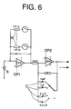
- the light detector 5 is a detector shown in FIG. 6 with a sensitivity between 20 pW / V and 2 mW / V at 0 to 13 V output voltage and a noise component of less than 1 mV, the input of which with PIN diodes 6 as a receiver for the LWL signals Is provided.
- a wavelength selection for example for a multi-channel optical fiber arrangement in the colors RED, GREEN, BLUE, WHITE, is obtained by using PIN diodes can be used with vapor-deposited interference filters. Standard SMA plugs are used to connect the FO to the light source 4 and the receiver 6.
- the circuit of the light detector 5 consists of two amplification stages OP1 and OP2.
- the photocurrent of the PIN diode is amplified with an OPA1 operational amplifier as an I / U converter.
- the diode lies between the inverting and the non-inverting input of the OPA1, the latter being connected to ground.
- the photocurrent flows in this circuit via one of the 7 measuring range resistors R (1 kOhm to 1 GOhm) to the output of the OPA1, whereby there is practically no voltage at the diode itself, which eliminates the temperature-dependent dark current of the diode.
- the output voltage then results directly from the photocurrent times the measuring resistor.
- This voltage is amplified once more by a factor of 10 in the second amplifier stage OP2, capacitors C in the negative feedback branch limiting the frequency response (eg 1 Hz and 10 »F result in 0.1 Hz as the upper frequency). This can further reduce the noise (100 »V ss at 10 Hz).
- the temperature drift is approx. 100 »V / K.
- the light detector 5 is connected to an evaluation device 8 via an analog / digital converter 7.
- This consists of a computer that either accepts the A / D converters as plug-in cards or is connected to an external unit via a serial (RS 232C) or parallel (IEEE 488) interface and software that records and evaluates the measured values .
- the evaluation consists first of all in converting the voltage value into a luminous intensity, taking into account the set sensitivities, and this in turn into an attenuation, taking into account the illuminance. Depending on the application, these values are then compared with threshold values or with target curves, ratios, differences and sums are formed, and the signals from various sensors are adapted to computational models of the observed process.
- the output is in the form of a continuous graphical display, the data is saved to a file, and if necessary the assessment of the signal is reduced to a simple "good / bad" statement.
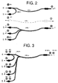
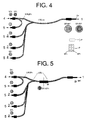
- FIGS. 2 to 5 Various fiber optic arrangements are shown schematically in FIGS. 2 to 5:
- the arrangement for transmission operation shown in FIG. 2 has an optical fiber 1 with 8 individual fibers SF8 and a reference optical fiber with one fiber on the transmission side.
- the end of an FO 3/4 is arranged in an opening 2 of the cuvette with both a transmission fiber SF 1 and one or more reception fibers EF 2 in a single-channel or multi-channel (FIG. 3) version.
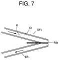
- FIG. 3 Another, also shown in Figure 3 embodiment for this mode of operation may consist in that three transmission fibers SF3 and three reception fibers EF1 are provided in pairs next to each other. It is advisable to grind the corresponding fiber ends protruding into the cuvette so that cladding C1 and core K of the fibers are removed to their center and the resulting quasi-tangential grinding surfaces with the interposition of a very thin metal plate Mp (10-20 »m ) in pairs ( Figure 7).
- the LWL 3/4 connected in an opening 2 to the cuvette 1 can contain one or more transmission fibers SF 3 and a reception fiber EF 1 per channel in accordance with a single or multi-channel operation.
- the ends of the fibers are closed with a transparent surface element, for example a 400 to 700 »m thick glass plate Gp, the end sections of the transmission fibers being inclined at an angle of 45 ° to the surface element, i.e.
- the light is irradiated at 45 °, the detection at an angle of 0 °, i.e. perpendicular to the interface.
- the ends of the transmit and receive fibers are arranged in pairs in a row (asymmetrical arrangement).
- An advantageous variant of this arrangement consists in a concentric distribution of many transmission fibers SF n on a 45 ° truncated cone around the ends of the receiving fibers EF 1 (symmetrical arrangement).
- the ends of the fibers are closed off with a prism P corresponding to the beam path of the total reflection instead of the surface element (dashed line).
- the ends of the transmit and receive fibers are in turn arranged in pairs, but without inclination of the end sections of the transmit fibers.
- FIG. 5 Another remission arrangement ( Figure 5) arises when a transmission fiber SF 1 and 3 reception fibers EF 1 do not collide perpendicularly with the surface element Gp, but on a thicker, approx. 3 m long fiber SF ′ 1 , so that a fiber switch W forms at this transition point.
- the end of the thicker fiber on the cuvette side is chamfered by 25 °, ie the angle to the fiber axis is not 90 °, but 65 ° to hide the final reflex.
- the possible uses of the photometric device according to the invention are diverse; e.g. for determining the color of suspensions or the size of the solid particles distributed therein or the solid concentration. These measurements can also be carried out simultaneously. This makes it possible to continuously monitor production processes with disperse phases, to obtain reference values for process control and to predetermine the quality of the solids produced.
Landscapes
- Physics & Mathematics (AREA)
- General Physics & Mathematics (AREA)
- Biochemistry (AREA)
- General Health & Medical Sciences (AREA)
- Health & Medical Sciences (AREA)
- Life Sciences & Earth Sciences (AREA)
- Chemical & Material Sciences (AREA)
- Analytical Chemistry (AREA)
- Optics & Photonics (AREA)
- Spectroscopy & Molecular Physics (AREA)
- Immunology (AREA)
- Pathology (AREA)
- Investigating Or Analysing Materials By Optical Means (AREA)
- Fire-Detection Mechanisms (AREA)
- Microscoopes, Condenser (AREA)
- Hybrid Cells (AREA)
- Optical Measuring Cells (AREA)
Claims (10)
- Dispositif photométrique pour la mesure du degré d'amortissement lors de la propagation de la lumière dans des systèmes à dispersion, composé d'une cuvette (1) pouvant être traversée par un courant, pour placer l'échantillon à examiner, avec au moins une ouverture latérale (2), pour effectuer le raccordement optique d'au moins un guide d'ondes lumineuses (LWL) d'une liaison de guide d'ondes lumineuses guidée depuis une source lumineuse (4), à l'intérieur de la cuvette, et, de là, à un photodétecteur (5), la liaison se faisant, vis-à-vis de l'intérieur de la cuvette, en vue de produire un signal de mesure, le guide d'ondes lumineuses (LWL) pénétrant par l'ouverture latérale (2) directement à l'intérieur de la cuvette (1), et le dispositif étant également composé d'une liaison de guide d'ondes lumineuses directe (LWL Rf) pour produire un signal de référence, ainsi que d'un appareil d'évaluation (8) raccordé au photodétecteur (5), le système composé de la source lumineuse, du photodétecteur et de l'appareil d'exploitation n'étant pas pulsé, caractérisé en ce que le photodétecteur (5) est un amplificateur à deux étages (OP1, OP2), dont l'entrée est liée à des diodes PIN (6), à titre de récepteur des signaux de guide d'ondes lumineuses, le premier étage d'amplificateur (OP1) étant un réseau à bouclage de réaction, pouvant être commuté jusqu'à présenter une résistance de bouclage de réaction très élevée, et le deuxième étage d'amplificateur (OP2) présentant un réseau à bouclage de réaction limitant la plage de fréquences au moyen de différentes capacités (C) pouvant être mises en circuit, de manière à obtenir une sensibilité allant jusqu'à 20 pW/V et un taux de bruit inférieur à 1 mV, pour une tension de sortie de l'ordre de 0 à 13 V.
- Dispositif photométrique selon la revendication 1, caractérisé en ce que la liaison à guide d'ondes lumineuses guidée sur la cuvette (1) est réalisée avec plusieurs canaux côté réception et les récepteurs (6) associés aux différents canaux ayant des sensibilités sélectives, dépendant des longueurs d'onde.
- Dispositif photométrique selon les revendications 1 et 2, caractérisé en ce que, dans un dispositif de transmission de la liaison de guide d'ondes lumineuses à la cuvette (1), sont raccordés un guide d'ondes lumineuses (LWL 1), situé côté émetteur, et un guide d'ondes lumineuses (LWL 2), situé côté récepteur et placé en regard de celui-ci.
- Dispositif photométrique selon les revendications 1 et 2, caractérisé en ce que, dans un dispositif à quasi-rétrodiffusion de la liaison à guide d'ondes lumineuses à une cuvette (1), un guide d'ondes lumineuses (LWL 3) est raccordé à une ou plusieurs fibres émettrices (SF₁, SF₃) et à une ou plusieurs fibres réceptrices (EF₁, EF₂)
- Dispositif photométrique selon la revendication 4, caractérisé en ce que les extrémités, situées côté cuvette, des fibres émettrice et réceptrice (SF₃, EF₁) sont disposées les unes à côtés des autres par paires, et la gaine et le noyau des extrémités de fibres étant enlevés par meulage, jusqu'à leur centre, de sorte que les faces meulées quasi-tangentielles produites viennent en appui entre elles, par paires, avec interposition d'une très mince plaquette métallique.
- Dispositif photométrique selon les revendications 1 et 2, caractérisé en ce que, dans un dispositif à réflexion diffuse de la liaison à guide d'ondes lumineuses sur la cuvette (1), un guide d'ondes lumineuses (LWL 3/4) est raccordé à une ou plusieurs fibres émettrices (SF) et fibres réceptrices (EF), et les extrémités de fibres étant délimitées par un élément de surface (Gp) transparent, les sections d'extrémité des fibres émettrices (SF) étant inclinées sous un angle de 45° par rapport aux éléments de surface.
- Dispositif photométrique selon la revendication 6, caractérisé en ce que les extrémités de la pluralité de fibres émettrices (SFn) sont disposées concentriquement sur une enveloppe tronconique dont l'angle est de 45° autour de la ou des extrémités des fibres réceptrices (EF₁).
- Dispositif photométrique selon les revendications 1 et 2, caractérisé en ce que dans un dispositif à réflexion diffuse de la liaison à guide d'ondes lumineuses, à la cuvette 1 est raccordé un guide d'ondes lumineuses (LWL 1) avec une fibre (SF₁), dont la face est meulée sous un angle de 25° par rapport à la verticale et la fibre réceptrice, respectivement les fibres réceptrices (EF₁), sont découplées au moyen d'une aiguille optique (W).
- Dispositif photométrique selon la revendication 1, caractérisé en ce que, dans un dispositif destiné à produire une réflexion totale (ATR) amortie de la liaison à guide d'ondes lumineuses, un guide d'ondes lumineuses (LWL 3/4) ayant plusieurs fibres émettrices (SF₃) et fibres réceptrices (EF₁) chaque fois disposées en rangées est raccordé à la cuvette (1), et les deux rangées de fibres étant délimitées à leurs extrémités avec un prisme (P), de manière correspondante au trajet du rayon de réflexion totale.
- Dispositif photométrique selon les revendications 1 à 9, caractérisé en ce que les récepteurs (6), associés aux différents canaux récepteurs, du photodétecteur (5) sont des diodes PIN avec des filtres à interférence destinés à différentes longueurs d'onde lumineuse et réalisés par métallisation sous vide.
Applications Claiming Priority (2)
| Application Number | Priority Date | Filing Date | Title |
|---|---|---|---|
| DE4024420A DE4024420A1 (de) | 1990-08-01 | 1990-08-01 | Photometrische messeinrichtung |
| DE4024420 | 1990-08-01 |
Publications (2)
| Publication Number | Publication Date |
|---|---|
| EP0472899A1 EP0472899A1 (fr) | 1992-03-04 |
| EP0472899B1 true EP0472899B1 (fr) | 1995-03-08 |
Family
ID=6411443
Family Applications (1)
| Application Number | Title | Priority Date | Filing Date |
|---|---|---|---|
| EP91112286A Expired - Lifetime EP0472899B1 (fr) | 1990-08-01 | 1991-07-23 | Dispositif de mesure photométrique |
Country Status (4)
| Country | Link |
|---|---|
| EP (1) | EP0472899B1 (fr) |
| AT (1) | ATE119666T1 (fr) |
| DE (2) | DE4024420A1 (fr) |
| ES (1) | ES2069136T3 (fr) |
Families Citing this family (16)
| Publication number | Priority date | Publication date | Assignee | Title |
|---|---|---|---|---|
| DE4139899A1 (de) * | 1991-12-04 | 1993-06-09 | Hoffmann, Alfred, Dr., 9200 Freiberg, De | Verfahren zur simultanmessung der truebung und des zeitlichen massenstromes suspendierter teilchen in fluessigkeiten |
| DE4328014A1 (de) * | 1993-08-20 | 1994-01-05 | Frank Minar | Verfahren zur Grauwassernutzung und Grauwasseranlage speziell für Einzelhaushalte mit Grauwassernutzung zur Toilettenspülung |
| US5394732A (en) * | 1993-09-10 | 1995-03-07 | Cobe Laboratories, Inc. | Method and apparatus for ultrasonic detection of air bubbles |
| SE502148C2 (sv) * | 1993-12-03 | 1995-08-28 | Bexelius | Anordning för mätning av mängden fast substans i ett fluidum med ljus |
| DE29607239U1 (de) * | 1996-04-23 | 1996-06-05 | J & M Analytische Mess- und Regeltechnik GmbH, 73431 Aalen | Kapillarhalter |
| DE19751557A1 (de) | 1997-11-20 | 1999-06-10 | Siemens Ag | Vorrichtung zur optimierten Signalzuführung in Kommunikationssystemen |
| DE10016023C2 (de) * | 2000-03-31 | 2003-01-30 | Glukomeditech Ag | Durchfluss-Messküvette und deren Verwendung |
| DE10242205B4 (de) * | 2002-09-10 | 2018-02-08 | Lios Technology Gmbh | Verfahren und Vorrichtung zur räumlich ausgedehnten Erfassung von Betriebszuständen |
| JP2006519385A (ja) | 2003-03-05 | 2006-08-24 | バセル ポリオレフィン イタリア エス.アール.エル. | 重合プロセスでの制御方法 |
| DE10330641A1 (de) | 2003-07-07 | 2005-02-03 | Basf Coatings Ag | Hochgenauer Remissionssensor zur Nassmessung von Lacken und Pigmentpasten |
| DE10351160B3 (de) * | 2003-11-03 | 2005-03-31 | Roche Diagnostics Gmbh | Durchfluß-Meßküvette und Transmissionsspektrometer zur Untersuchung biologischer Flüssigkeiten |
| DE10361058B3 (de) | 2003-12-22 | 2005-09-08 | Basf Coatings Ag | Hochgenauer strömungsorientierter Mehrwinkel-Remissionssensor |
| CN106132496B (zh) | 2014-03-19 | 2020-03-13 | 巴斯夫欧洲公司 | 用于将物质从溶液中分离出来的方法和装置 |
| EP3513168B1 (fr) | 2016-09-13 | 2020-08-05 | BASF Coatings GmbH | Capteur pour la mesure sequentielle de l'émission et/ou de la diffusion vers l'avant et/ou de la luminance de réflexion ou pour la mesure simultanée de la transmission et de la diffusion vers l'avant ou de la transmission et de la luminance de réflexion d'un échantillon |
| CN111938595B (zh) * | 2020-08-14 | 2025-09-30 | 浙江清华柔性电子技术研究院 | 脑成像检测装置 |
| CN119985407B (zh) * | 2025-01-09 | 2025-12-26 | 西北工业大学 | 一种高灵敏度多气体检测的波导阵列气体传感系统 |
Family Cites Families (3)
| Publication number | Priority date | Publication date | Assignee | Title |
|---|---|---|---|---|
| DE2231873A1 (de) * | 1972-06-29 | 1974-01-17 | Ver Foerderung Inst Kunststoff | Einrichtung zum messen und zaehlen von partikeln in einem stroemenden lichtdurchlaessigen medium mittels licht |
| FR2453399A1 (fr) * | 1979-04-04 | 1980-10-31 | Rech Machines Thermiqu Centre | Capteur optique pour la mesure des concentrations |
| FR2615952B1 (fr) * | 1987-05-27 | 1990-04-20 | Elf Aquitaine | Dispositif pour la determination d'au moins la concentration de particules solides en suspension dans un fluide |
-
1990
- 1990-08-01 DE DE4024420A patent/DE4024420A1/de not_active Withdrawn
-
1991
- 1991-07-23 EP EP91112286A patent/EP0472899B1/fr not_active Expired - Lifetime
- 1991-07-23 DE DE59104856T patent/DE59104856D1/de not_active Expired - Fee Related
- 1991-07-23 AT AT91112286T patent/ATE119666T1/de not_active IP Right Cessation
- 1991-07-23 ES ES91112286T patent/ES2069136T3/es not_active Expired - Lifetime
Non-Patent Citations (2)
| Title |
|---|
| P. Horowitz und W.Hill: "The art of electronics", Cambridge University Press, 1989, S.996,997 * |
| U. Tietze, C.Schenk: "Halbleiterschaltungstechnik", Springer Verlag, 1985, S.106-108 * |
Also Published As
| Publication number | Publication date |
|---|---|
| ES2069136T3 (es) | 1995-05-01 |
| DE59104856D1 (de) | 1995-04-13 |
| DE4024420A1 (de) | 1992-02-06 |
| EP0472899A1 (fr) | 1992-03-04 |
| ATE119666T1 (de) | 1995-03-15 |
Similar Documents
| Publication | Publication Date | Title |
|---|---|---|
| DE3688349T2 (de) | System zur chemischen Fernanalyse. | |
| DE69636862T2 (de) | Vorrichtung zur Messung von Raman-Streulicht | |
| EP0472899A1 (fr) | Dispositif de mesure photométrique | |
| DE10008517C2 (de) | Optisches Meßsystem | |
| DE3103476C2 (fr) | ||
| DE69636403T2 (de) | Spektrometrie und optisches Messverfahren und Vorrichtung | |
| DE2818674A1 (de) | Vorrichtung zum messen von daempfungscharakteristiken und zum lokalisieren von fehlern in optischen fasern | |
| DE3418839A1 (de) | Geraet zur kolorimetrie/photometrie | |
| DE2460434A1 (de) | Flud-analysator | |
| EP0597059B1 (fr) | Dispositif et procede pour la mesure de concentrations de substances solides dans des liquides | |
| DE19509822C2 (de) | Ölkonzentrations-Meßgerät | |
| EP0660106B1 (fr) | Dispositif avec spectrophotomètre et fibres optiques | |
| DE60205406T2 (de) | Optisches zweiwellenlängen-fluoreszenzanalysegerät | |
| DE3938142C2 (fr) | ||
| DE69735565T2 (de) | Optisches Messgerät mit wellenlängenselektiver Lichtquelle | |
| EP1054252A2 (fr) | Dispositif de mesure optique pour déterminer le rayonnement transmis et diffusé | |
| DE4411063A1 (de) | Verfahren zur Bestimmung der Dispersionsnullstelle eines Lichtwellenleiters | |
| DE68901727T2 (de) | Optischer leistungsmesser. | |
| DE10149879B4 (de) | Vorrichtung zur spektralphotometrischen Analyse von flüssigen Medien | |
| DE112021005257T5 (de) | Optisches extinktionsspektrometer, optisches bauelement und verfahren zur optischen extinktionsspektrometrie | |
| DE4325529A1 (de) | Vorrichtung zum Bestimmen der Konzentration von Stoffen im Blut | |
| EP0043522B1 (fr) | Réfractomètre | |
| DE4407332A1 (de) | Verfahren zur Bestimmung der Extinktion oder Transmission und Photometer | |
| DE4112528C2 (de) | Spektralfotometer | |
| DE3813718C2 (fr) |
Legal Events
| Date | Code | Title | Description |
|---|---|---|---|
| PUAI | Public reference made under article 153(3) epc to a published international application that has entered the european phase |
Free format text: ORIGINAL CODE: 0009012 |
|
| AK | Designated contracting states |
Kind code of ref document: A1 Designated state(s): AT BE CH DE ES FR GB IT LI NL |
|
| 17P | Request for examination filed |
Effective date: 19920220 |
|
| 17Q | First examination report despatched |
Effective date: 19940216 |
|
| GRAA | (expected) grant |
Free format text: ORIGINAL CODE: 0009210 |
|
| AK | Designated contracting states |
Kind code of ref document: B1 Designated state(s): AT BE CH DE ES FR GB IT LI NL |
|
| REF | Corresponds to: |
Ref document number: 119666 Country of ref document: AT Date of ref document: 19950315 Kind code of ref document: T |
|
| REF | Corresponds to: |
Ref document number: 59104856 Country of ref document: DE Date of ref document: 19950413 |
|
| GBT | Gb: translation of ep patent filed (gb section 77(6)(a)/1977) |
Effective date: 19950323 |
|
| ITF | It: translation for a ep patent filed | ||
| REG | Reference to a national code |
Ref country code: ES Ref legal event code: FG2A Ref document number: 2069136 Country of ref document: ES Kind code of ref document: T3 |
|
| ET | Fr: translation filed | ||
| PLBE | No opposition filed within time limit |
Free format text: ORIGINAL CODE: 0009261 |
|
| STAA | Information on the status of an ep patent application or granted ep patent |
Free format text: STATUS: NO OPPOSITION FILED WITHIN TIME LIMIT |
|
| 26N | No opposition filed | ||
| REG | Reference to a national code |
Ref country code: GB Ref legal event code: IF02 |
|
| PGFP | Annual fee paid to national office [announced via postgrant information from national office to epo] |
Ref country code: ES Payment date: 20080821 Year of fee payment: 18 Ref country code: CH Payment date: 20080815 Year of fee payment: 18 Ref country code: DE Payment date: 20080807 Year of fee payment: 18 |
|
| PGFP | Annual fee paid to national office [announced via postgrant information from national office to epo] |
Ref country code: IT Payment date: 20080730 Year of fee payment: 18 Ref country code: NL Payment date: 20080703 Year of fee payment: 18 Ref country code: AT Payment date: 20080711 Year of fee payment: 18 Ref country code: FR Payment date: 20080718 Year of fee payment: 18 |
|
| PGFP | Annual fee paid to national office [announced via postgrant information from national office to epo] |
Ref country code: GB Payment date: 20080723 Year of fee payment: 18 |
|
| PGFP | Annual fee paid to national office [announced via postgrant information from national office to epo] |
Ref country code: BE Payment date: 20090126 Year of fee payment: 18 |
|
| BERE | Be: lapsed |
Owner name: *BASF A.G. Effective date: 20090731 |
|
| REG | Reference to a national code |
Ref country code: CH Ref legal event code: PL |
|
| GBPC | Gb: european patent ceased through non-payment of renewal fee |
Effective date: 20090723 |
|
| NLV4 | Nl: lapsed or anulled due to non-payment of the annual fee |
Effective date: 20100201 |
|
| REG | Reference to a national code |
Ref country code: FR Ref legal event code: ST Effective date: 20100331 |
|
| PG25 | Lapsed in a contracting state [announced via postgrant information from national office to epo] |
Ref country code: LI Free format text: LAPSE BECAUSE OF NON-PAYMENT OF DUE FEES Effective date: 20090731 Ref country code: CH Free format text: LAPSE BECAUSE OF NON-PAYMENT OF DUE FEES Effective date: 20090731 Ref country code: FR Free format text: LAPSE BECAUSE OF NON-PAYMENT OF DUE FEES Effective date: 20090731 |
|
| PG25 | Lapsed in a contracting state [announced via postgrant information from national office to epo] |
Ref country code: GB Free format text: LAPSE BECAUSE OF NON-PAYMENT OF DUE FEES Effective date: 20090723 |
|
| PG25 | Lapsed in a contracting state [announced via postgrant information from national office to epo] |
Ref country code: BE Free format text: LAPSE BECAUSE OF NON-PAYMENT OF DUE FEES Effective date: 20090731 Ref country code: DE Free format text: LAPSE BECAUSE OF NON-PAYMENT OF DUE FEES Effective date: 20100202 Ref country code: AT Free format text: LAPSE BECAUSE OF NON-PAYMENT OF DUE FEES Effective date: 20090723 |
|
| REG | Reference to a national code |
Ref country code: ES Ref legal event code: FD2A Effective date: 20090724 |
|
| PG25 | Lapsed in a contracting state [announced via postgrant information from national office to epo] |
Ref country code: ES Free format text: LAPSE BECAUSE OF NON-PAYMENT OF DUE FEES Effective date: 20090724 |
|
| PG25 | Lapsed in a contracting state [announced via postgrant information from national office to epo] |
Ref country code: IT Free format text: LAPSE BECAUSE OF NON-PAYMENT OF DUE FEES Effective date: 20090723 |
|
| PG25 | Lapsed in a contracting state [announced via postgrant information from national office to epo] |
Ref country code: NL Free format text: LAPSE BECAUSE OF NON-PAYMENT OF DUE FEES Effective date: 20100201 |