EP0473591B1 - 4:3 anpassbares perforationsrad - Google Patents
4:3 anpassbares perforationsrad Download PDFInfo
- Publication number
- EP0473591B1 EP0473591B1 EP90903472A EP90903472A EP0473591B1 EP 0473591 B1 EP0473591 B1 EP 0473591B1 EP 90903472 A EP90903472 A EP 90903472A EP 90903472 A EP90903472 A EP 90903472A EP 0473591 B1 EP0473591 B1 EP 0473591B1
- Authority
- EP
- European Patent Office
- Prior art keywords
- film
- sleeve
- perf
- teeth
- sprocket assembly
- Prior art date
- Legal status (The legal status is an assumption and is not a legal conclusion. Google has not performed a legal analysis and makes no representation as to the accuracy of the status listed.)
- Expired - Lifetime
Links
- 238000006243 chemical reaction Methods 0.000 title description 12
- 238000000926 separation method Methods 0.000 claims description 2
- 238000004519 manufacturing process Methods 0.000 description 18
- 230000000694 effects Effects 0.000 description 6
- 229910000831 Steel Inorganic materials 0.000 description 4
- 239000000463 material Substances 0.000 description 4
- 238000000034 method Methods 0.000 description 4
- 239000010959 steel Substances 0.000 description 4
- 238000000429 assembly Methods 0.000 description 2
- 238000012986 modification Methods 0.000 description 2
- 230000004048 modification Effects 0.000 description 2
- 230000003287 optical effect Effects 0.000 description 2
- 244000144985 peep Species 0.000 description 2
- 239000007787 solid Substances 0.000 description 2
- 206010017577 Gait disturbance Diseases 0.000 description 1
- 229910052782 aluminium Inorganic materials 0.000 description 1
- XAGFODPZIPBFFR-UHFFFAOYSA-N aluminium Chemical compound [Al] XAGFODPZIPBFFR-UHFFFAOYSA-N 0.000 description 1
- 230000000712 assembly Effects 0.000 description 1
- 210000000078 claw Anatomy 0.000 description 1
- 230000000295 complement effect Effects 0.000 description 1
- 239000013070 direct material Substances 0.000 description 1
- 230000009977 dual effect Effects 0.000 description 1
- 230000014509 gene expression Effects 0.000 description 1
- 238000009434 installation Methods 0.000 description 1
- 239000003562 lightweight material Substances 0.000 description 1
- 229910052751 metal Inorganic materials 0.000 description 1
- 239000002184 metal Substances 0.000 description 1
- 239000002699 waste material Substances 0.000 description 1
Images

Classifications
-
- G—PHYSICS
- G03—PHOTOGRAPHY; CINEMATOGRAPHY; ANALOGOUS TECHNIQUES USING WAVES OTHER THAN OPTICAL WAVES; ELECTROGRAPHY; HOLOGRAPHY
- G03B—APPARATUS OR ARRANGEMENTS FOR TAKING PHOTOGRAPHS OR FOR PROJECTING OR VIEWING THEM; APPARATUS OR ARRANGEMENTS EMPLOYING ANALOGOUS TECHNIQUES USING WAVES OTHER THAN OPTICAL WAVES; ACCESSORIES THEREFOR
- G03B1/00—Film strip handling
- G03B1/18—Moving film strip by means which act on the film between the ends thereof
- G03B1/20—Acting means
- G03B1/24—Sprockets engaging holes in the film
Definitions
- the present invention relates to a sprocket assembly which, when mounted on a film projector or other film handling device, permits the ready conversion of the device to run either 4-perf or 3-perf film, as the occasion requires.
- the full aperture format had a 4:3 ratio of frame width to frame length (the length being measured along the longitudinal extent of the film), otherwise known as the 1.33 aspect ratio, and resulted in nearly the entire length of film being exposed or utilized, since there was very little unexposed film between frames.
- the image size on the film was reduced to allow room for the sound track to be printed adjacent to one row of perfs. In order to accommodate the sound track, the image size was reduced in both width and length, maintaining the 4:3 or 1.33 aspect ratio, so that a greater amount of unused or unexposed film was left between frames.
- the reduced size, 4:3 ratio frame format is known as the "academy aperture.”
- the 4:3 frame format was changed to accommodate projection on a flat, wide screen.
- the image size was reduced from the academy aperture and conformed into a 5.5:3 ratio, popularly known as the 1.85 aspect ratio.
- the flat, wide screen frame format was conformed into a 1.66 aspect ratio, which again resulted in an image size smaller than that obtained with the academy aperture.
- two techniques are presently employed: (i) a mask is placed in the projector gate, or (ii) a "hard matte" is used in the camera.
- the 35 mm camera advances the film four perfs at a time, for each frame.
- the mask in the projector gate is employed when a camera is used for filming which is adapted to produce an image on the film having a 1.33 aspect ratio, since it is necessary to restrict the height of the 1.33 frame when projecting onto a screen requiring a 1.85 or 1.66 frame.
- the mask in the projector gate cuts off the unnecessary top and bottom portions of the 1.33 image so that it will fit the 1.85 or 1.66 image format.
- the "hard matte,” which is also a type of mask, in the camera is used to record a photographic image which has the correct wide screen ratio. The mask in the camera results in a wide, unexposed portion of film between each frame and the adjacent frames.
- the amount of film used is of the order of one-third greater than the combined length of the photographic images and the required spacing between images, assuming, again, that 4-perf pulldown is employed. In other words, about 25% of each film is presently not being used. This excess film results in unnecessary expense for buying, processing, editing, and printing of the film used for motion pictures, as well as extra expense for storage, shipping, handling, and the like.
- Cinemascope Another wide-screen film technique known as Cinemascope was introduced in the early 1950's.
- Cinemascope achieved a 2.35 aspect ratio through the use of anamorphic lenses, which squeezed the image into the 4:3 academy aperture frame in production, and subsequently unsqueezed it in projection onto a wide, curved screen.
- a 4-perf pulldown 35 mm camera with a 2:1 anamorphic optical system would be used filming.
- This system reduces the horizontal component of the scene which is recorded on the film.
- the projector uses a complementary 2:1 anamorphic optical system such that the horizontal component of the image is increased to conform the proportions of the projected image to those of the scene filmed.
- the flat, wide screen format is more popular and widely used than the anamorphic 2.35 format.
- the 3-perf sprockets for this conventional system being sized at 75% of the diameter (and, thus, the circumference as well) of the larger 4-perf sprockets, would have only 12 teeth around their circumferential peripheries at each end.
- the lower cost of the film for the 25% shorter prints but also to savings in printing or processing, storage, handling, shipping, and the like of such shorter, lighter weight films. Since many more release prints are made than production prints, the savings to be realized from making 3-perf release prints are potentially greater than those to be realized through simply making 3-perf production prints.
- Three-perf film running at 30 fps uses 25.72 m (84.375 feet) of film per minute, compared with 27.4 m (90 feet) per minute for 4-perf film running at 24 fps. These same relative film savings of about 6% will accrue whether one is using 3-perf film to produce standard video or High Definition TV. The latter is expected to become increasingly popular.
- the present invention solves the problems discussed above in connection with prior art film production and projection systems and will enable the film industry to capture the potential vast cost savings referred to previously by providing a device which will allow fast, fairly simple, relatively inexpensive changeovers in existing projection equipment, once modified with a one-time conversion to the smaller (e.q., 12-tooth) sprockets, to accommodate either 4-perf or the proposed new 3-perf pulldown films.
- the one-time conversion to the 12-tooth, smaller sprockets will enable the projection equipment to run the proposed 3-perf films.
- the present invention will allow a simple change to be made to those 12-tooth sprockets to permit the same equipment to run 4-perf films.
- a sprocket assembly for converting a film projector or other film handling device having at least one rotatable shaft to make it compatible with either 3-perf or 4-perf film, such films having a predetermined spacing between perfs that is the same for both films, the assembly comprising: an inner cylindrical sleeve having first means disposed around its circumference at each end for sequentially engaging the perfs when the inner sleeve is rotated; mounting means disposed on the inner cylindrical sleeve for non-rotatably mounting the inner sleeve on a projector shaft; an outer cylindrical sleeve telescopically slidable over the inner cylindrical sleeve and having second means disposed around its circumference at each end for sequentially engaging the perfs when the outer sleeve is rotated; and interengageable locking means disposed on the inner and outer sleeves for antirotationally locking the inner sleeve within the outer sleeve; the outside diameter of the second means
- the teeth on the inner sleeve mate with a plurality of grooves or splines on the inner surface of the outer sleeve.
- the inner sleeve preferably includes a set screw which can be fitted into an opening in the outer sleeve. This locks the outer sleeve to the inner sleeve in a longitudinally axial direction, preventing one sleeve from being removed from the other in such axial direction.
- the diameter of the outer sleeve, and, thus, the circumference is 4/3 that of the diameter and, thus, the circumference, of the inner sleeve, and, because the teeth are spaced apart the same distance as the film perforations, the outer sleeve has 4/3 as many teeth as the inner sleeve.
- the outer sleeve ⁇ inner sleeve combined assembly will engage 4/3 as much film in a given time period as the inner sleeve alone.
- the outer sleeve When the outer sleeve is installed on the inner sleeve, the combination of the inner and outer sleeves, with the outer sleeve engaging the film, will run 27.4 m (90 feet) of film per minute if shaft speed remains the same, corresponding to the 4-perf projection rate.
- Figure 1 is an isometric view showing a relatively heavy feed or hold-back sprocket typical of those currently in use.
- Figure 2 is an isometric view showing an intermittent sprocket typical of those currently in use.
- Figure 3 is an isometric view of one preferred embodiment of the inner sleeve of the sprocket assembly of the present invention.
- Figure 4 is an isometric view of an intermittent sprocket suitable for use with the sprocket assembly of the present invention.
- Figure 5 is an isometric view of one preferred embodiment of the outer sleeve of the sprocket assembly of the present invention.
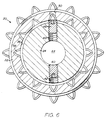
- Figure 6 is an enlarged, vertical cross-sectional view of the sprocket assembly of the present invention, taken along lines 6-6 shown in Figure 5 and with the inner sleeve of Figure 3 installed in the outer sleeve of Figure 5.
- a conventional sprocket 2 which may be either a feed or hold-back sprocket, for example, designed for use in a film projector or other film handling device (for example, a telecine, used in conversion of films to video) to run 4-perf film.
- Sprocket 2 has a relatively heavy, substantially solid body of metal such as steel or other suitable material and includes two sets of teeth, 3 and 4, respectively, around its circumference at its ends for engaging the perforations at the edges of movie film, for example, 35 mm film, as the film is run.
- the teeth of sets 3, 4 of sprocket 2 are of conventional shape or profile and have a pitch length, or distance between adjacent teeth, which is standard in the film industry.
- Sprocket 2 also has a central longitudinal axial bore 6 adapted for receiving a rotatable shaft, such as the drive shaft, for example, of the projector.
- an intermittent sprocket 8 of a conventional type which may be used, for example, in the projector or other film handling device referred to in connection with sprocket 2.
- Sprocket 8 has two wheel-like bodies 9, 10, joined by axle or shaft 12, all of lightweight material, such as light gauge steel, aluminum, or other suitable material.
- Sprocket 8 may include a plurality of blind perforations 14 in its end faces.
- Sprocket 8 also includes two sets of teeth 16, 18 around the circumference of wheel-like bodies 9, 10, respectively, for engaging the perfs of the film to be run through the projector or other film handling device.
- sprocket 8 The circumference of sprocket 8 around teeth 16, 18 is typically the same as that of sprocket 2 around teeth 3, 4, and like sprocket 2, the teeth of sprocket 8 have a conventional shape or profile and standard film industry pitch length. Sprocket 8 is considerably lighter in weight than sprocket 2.
- Sprocket assembly 20 includes an outer sleeve 22 ( Figure 5) and an inner sleeve 24 ( Figure 3), each having means for engaging standard movie film perforations, such as 35 mm film perforations, when the film is run through the projector or other film handling device.
- Such means includes two sets of teeth 26A, 26B, and 28A, 28B, around the circumference of sleeves 22, 24, respectively, at their ends.
- Such means further includes a pair of collars 30A, 30B on outer sleeve 22, and a pair of collars 32A, 32B on inner sleeve 24, each collar forming a base for one of the sets of teeth 26A, 26B and 28A, 28B.
- the collars are preferably integral with the bodies of sleeves 22, 24.
- the teeth of sets 26A, 26B, 28A, 28B are preferably all of conventional shape and preferably have a pitch length equal to the present film industry standard.
- the diameter of collars 30A, 30B is 4/3 the diameter of collars 32A, 32B.
- the circumference of collars 30A, 30B is 4/3 that of collars 32A, 32B.
- the inner sleeve 24 has a relatively heavy, substantially solid body 25 of steel or other suitable material with a reduced O.D. mid-portion 27.
- Reduced O.D. mid-portion 27 is adapted to be spaced from the film surface as the film travels by on sleeve 24, so that the images on the film will not be damaged by engagement with the surface of the sleeve.
- Outer sleeve 22 has a relatively heavy body 29 of steel or other suitable material, and it, too, has a reduced O.D. mid-portion 31 to space the sleeve's surface from that of the film as the film is passed along the sleeve.
- the teeth in the sets 26A, 26B and 28A, 28B are, as mentioned above, spaced the same distance apart as the perforations on the edges of the film for which sprocket assembly 20 is to be used.
- that distance will be the standard industry pitch length, as referred to above. It should be understood, however, that other pitch lengths could be used, and the teeth on sleeves 22, 24 would then be spaced according to that other pitch length.
- the longitudinal distance between the sets of teeth 26A and 26B, and the longitudinal distance between the sets of teeth 28A and 28B is substantially the same as the width of the film between the perforations on the edges of the film. Again, for standard films that distance will be set, but any other distance could be used.
- sleeves 22 and 24 are substantially the same as the width of the film to be run with sprocket assembly 20.
- sets of teeth 26A, 26B and 28A, 28B are aligned to engage the film perforations in sequence as pulldown occurs.
- Inner sleeve 24 and outer sleeve 22 are designed to be mated to rotate together. As indicated in Figure 6, inner sleeve 24 is adapted to be telescoped into a bore 36 in outer sleeve 22. A plurality of longitudinally axially extending grooves or splines 38 are circumferentially spaced apart around the inner wall surface of bore 36 of outer sleeve 22. The teeth 28A, 28B are received in splines 38 when inner sleeve 24 is inserted into bore 36 of outer sleeve 22. Rotation of inner sleeve 24 within outer sleeve 22 is prevented by engagement of teeth 28A, 28B with the walls of splines 38.
- Grooves or splines 38 extend substantially parallel to the longitudinal axis of outer sleeve 22 along the entire length of sleeve 22. According to one embodiment of the invention, there are the same number of splines 38 as the number of teeth in each set 28A, 28B. There may be fewer splines, as long as the desired antirotational effect is achieved. For example, if splines 38 were wide enough (measured in a circumferential direction) to accommodate two adjacent teeth therewithin, only half as many splines would be required as teeth. For a 12-tooth inner sleeve 24, for example, only six splines would be required. It is believed that the desired antirotational effect could be achieved with as little as one spline.
- each groove 38 is sized to accommodate one pair of opposed teeth, i.e.
- one tooth from each of the sets of teeth 28A, 28B resides in each groove 38 when inner sleeve 24 is telescoped within outer sleeve 22.
- a set screw 40 is threaded into a radially or transversely extending bore 42 in inner sleeve 24 and can be tightened against a shaft 44 of a projector or other film handling device for locking inner sleeve 24 to shaft 44 to prevent relative axial or rotational movement of inner sleeve 24 or sprocket assembly 20 with respect to shaft 44, and to permit shaft 44 to rotate as a unit with the inner sleeve or the combined sprocket assembly.
- shaft 44 and inner sleeve 24 can be accomplished by other means, for example a spring-loaded ball in one member which mates with a seat or groove in the other. Still other means of locking the inner sleeve on shaft 44 will no doubt be apparent to those skilled in the art.
- a second set screw 46 is threaded into a second radially or transversely extending bore 48 in inner sleeve 24.
- Inner sleeve 24 is oriented within outer sleeve 22 so that bore 48 is in register with a radially or transversely extending bore 50 in outer sleeve 22.
- Set screw 46 is adapted to be backed out from bore 48 and partially into bore 50 in order to lock inner sleeve 24 and outer sleeve 22 together axially, i.e. , to prevent the axial separation of sleeves 22, 24. Again, this locking could also be accomplished with other means, for example the spring-loaded ball and seat arrangement referred to above, or any other suitable means.
- the ratio of the diameters, circumferences, and numbers of teeth for sleeves 22, 24 is 4:3.
- Figures 3-6 which is designed to run conventional movie film such as 35 mm film, there are 16 teeth on each end of outer sleeve 22 and 12 teeth on each end of inner sleeve 24.
- Sleeves 22 and 24 can be larger or smaller and can have a greater or lesser number of teeth, provided that the 4:3 ratio is maintained.
- Sprocket assembly 20 is designed to be attached to a rotating or rotatable shaft of a projector.
- a central axial bore 52 through inner sleeve 24 is adapted to be telescoped over the shaft, e.g. , a drive shaft, of the projector (not shown) and mated therewith, e.g. , through tightening set screw 40 against the shaft, so that sprocket assembly 20 can be rotated with the shaft.
- a conventional projector has several sprockets which engage the film. It is contemplated that a sprocket assembly 20 will replace all of the sprockets in the projector, including the feed and hold-back sprockets and the constant-speed sprockets, but not the lightweight intermittent sprocket 8, shown in Figure 2. To run 3-perf film, intermittent sprocket 8 is preferably completely removed and replaced with an intermittent sprocket which is 3/4 its diameter, such as intermittent sprocket 60 shown in Figure 4.
- tooth-to-groove locking mechanism for locking the inner and outer sleeves together
- the present invention is not limited to any particular form of antirotationally locking together the inner and outer sleeves.
- Other locking means could be used, so long as a secure, reliable connection is obtained.
- bore 36 could be milled or drilled out to be substantially the same diameter as the tooth-tip-to-tooth-tip diameter of inner sleeve 24, and a nut and bolt could be placed in aligned bores through outer sleeve 22 and inner sleeve 24 to hold them together.
- the present invention can be employed in any concentrically disposed dual sprocket system for film production or projection to effect a 4:3 perf conversion.
Landscapes
- Physics & Mathematics (AREA)
- General Physics & Mathematics (AREA)
- Studio Devices (AREA)
- Storage Of Web-Like Or Filamentary Materials (AREA)
- Advancing Webs (AREA)
- Gears, Cams (AREA)
- Details Of Rigid Or Semi-Rigid Containers (AREA)
- Devices For Conveying Motion By Means Of Endless Flexible Members (AREA)
- Storing, Repeated Paying-Out, And Re-Storing Of Elongated Articles (AREA)
- Registering, Tensioning, Guiding Webs, And Rollers Therefor (AREA)
Claims (15)
- Zahnrollenbaugruppe zum Anpassen eines Filmprojektors oder einer anderen Filmhandhabungsvorrichtung mit mindestens einer drehbaren Welle, um diese(n) mit Filmen mit drei oder vier Perforationslochpaaren je Bild kompatibel zu machen, wobei solche Filme einen vorbestimmten Abstand zwischen den Perforationen aufweisen, welcher für beide Filme gleich ist, versehen mit:
einer zylindrischen Innenhülse (24), die an jedem Ende um deren Umfang angeordnete erste Anordnungen (28A, 28B) aufweist, die mit den Perforationen sequentiell in Eingrifftreten, wenn die Innenhülse gedreht wird;
einer an der zylindrischen Innenhülse angeordneten Montageanordnung (40, 42) zum drehfesten Montierten der Innenhülse auf einer Projektorwelle (44);
einer zylindrischen Außenhülse (22), die teleskopartig über die zylindrische Innenhülse gleiten kann und die an jedem Ende um deren Umfang angeordnete zweite Anordnungen (26A, 26B) aufweist, um sequentiell mit den Perforationen in Eingriff zu treten, wenn die Außenhülse gedreht wird; und
miteinander in Eingriff bringbaren Verriegelungsanordnungen (28A, 28B, 38), die an der Innen- und der Außenhülse angeordnet sind, um die Innenhülse innerhalb der Außenhülse drehfest zu blockieren, wobei der Außendurchmesser der zweiten Anordnung zum sequentiellen Ineingrifftreten mit den Perforationen im wesentlichen 4/3 des Außendurchmessers der ersten Anordnung zum sequentiellen Ineingrifftreten mit den Perforationen beträgt. - Zahnrollenbaugruppe nach Anspruch 1, bei welcher die ersten und zweiten Anordnungen (28A, 28B, 26A, 26B) zum sequentiellen Ineingrifftreten mit den Perforationen jeweils zwei Sätze von Transportzähnen aufweisen, wobei die benachbarten Zähne von jedem Satz in Umfangsrichtung in einem Abstand angeordnet sind, welcher dem Abstand der Filmperforationen entspricht.
- Zahnrollenbaugruppe nach Anspruch 2, bei welcher die Zähne (28A, 28B) auf der Innenhülse (24) drehfest in Eingriff mit der Innenseite der Außenhülse (22) treten.
- Zahnrollenbaugruppe nach Anspruch 3, bei welcher die Innenfläche (36) der Außenhülse (22) mindestens eine in Längsrichtung axial verlaufende Nut (38) aufweist, um mindestens ein gegenüberliegendes Paar von Zähnen (28A, 28B) der Innenhülse (24) aufzunehmen, wenn die Innenhülse in die Außenhülse eingeschoben wird.
- Zahnrollenbaugruppe nach Anspruch 4, bei welcher die Zähne (28A, 28B) der Innenhülse (24) passend mit den Nuten (38) in Eingrifftreten.
- Zahnrollenbaugruppe nach Anspruch 1, bei welcher die Montageanordnung eine Stellschraube (40) aufweist, die in einer radial verlaufenden Gewindebohrung (42) in der Innenhülse (24) angeordnet ist, um mit der Projektorwelle in Eingriff zu treten.
- Zahnrollenbaugruppe nach Anspruch 6, bei welcher die Innenhülse (24) eine zweite Stellschraube (46) aufweist, die in einer zweiten radial verlaufenden Gewindebohrung (48) in der Innenhülse angeordnet ist, und die mit einer radial verlaufenden Bohrung in der Außenhülse (22) in Eingriff bringbar ist, um ein axiales Trennen der Hülsen zu verhindern.
- Zahnrollenbaugruppe nach Anspruch 1, bei welcher die Innenhülse (24) ausgelegt ist, um mit der Antriebswelle (44) des Projektors derart in Verriegelungseingriff zu treten, daß eine Axial- oder Drehbewegung der Innenhülse gegenüber der Antriebswelle (44) verhindert wird.
- Zahnrollenbaugruppe nach Anspruch 2, bei welcher die Innen- und die Außenhülse (24, 22) im wesentlichen die gleiche Länge aufweisen und die Sätze der Zähne (28A, 28B, 26A, 26B) jeder Hülse im wesentlichen in gleichem Abstand in Längsrichtung angeordnet sind.
- Zahnrollenbaugruppe nach Anspruch 9, bei welcher die Länge der Innen- und der Außenhülse (24, 22) im wesentlichen der Breite eines 35 mm Films entspricht.
- Zähnrollenbaugruppe nach Anspruch 2, bei welcher die Innen- und die Außenhülse (24, 22) jeweils einen erhabenen Kragen um ihre jeweiligen Enden aufweisen, wobei jeder Kragen eine Basis für den Satz von Zähnen an den entsprechenden Enden der Hülsen bildet.
- Zähnrollenbaugruppe nach Anspruch 2, bei welcher die Innenhülse (24) 12 Zähne aufweist, und die Außenhülse (24) 16 Zähne aufweist.
- Zahnrollenbaugruppe nach Anspruch 12, bei welcher die Zähne (28A, 28B, 26A, 26B) eine Teilungslänge haben, die im wesentlichen der in der Filmindustrie gebräuchlichen Teilungslänge entspricht.
- Zahnrollenbaugruppe nach Anspruch 2, bei welcher die in Umfangsrichtung gemessene Teilung der in der Filmindustrie gebräuchlichen Teilung entspricht.
- Zahnrollenbaugruppe nach Anspruch 2, bei welcher die in Umfangsrichtung gemessene Teilung derjenigen von Filmen mit drei oder vier Perforationslochpaaren je Bild entspricht.
Applications Claiming Priority (3)
| Application Number | Priority Date | Filing Date | Title |
|---|---|---|---|
| US07/358,550 US4900293A (en) | 1989-05-26 | 1989-05-26 | 4:3 perf conversion sprocket |
| PCT/US1990/000675 WO1990014533A1 (en) | 1989-05-26 | 1990-02-06 | 4:3 perf conversion sprocket |
| US358550 | 1999-07-22 |
Publications (3)
| Publication Number | Publication Date |
|---|---|
| EP0473591A1 EP0473591A1 (de) | 1992-03-11 |
| EP0473591A4 EP0473591A4 (en) | 1992-10-28 |
| EP0473591B1 true EP0473591B1 (de) | 1995-12-06 |
Family
ID=23410111
Family Applications (1)
| Application Number | Title | Priority Date | Filing Date |
|---|---|---|---|
| EP90903472A Expired - Lifetime EP0473591B1 (de) | 1989-05-26 | 1990-02-06 | 4:3 anpassbares perforationsrad |
Country Status (11)
| Country | Link |
|---|---|
| US (1) | US4900293A (de) |
| EP (1) | EP0473591B1 (de) |
| JP (1) | JPH04507298A (de) |
| CN (1) | CN1023261C (de) |
| AT (1) | ATE131291T1 (de) |
| AU (1) | AU5098090A (de) |
| CA (1) | CA2057012C (de) |
| DE (1) | DE69024048T2 (de) |
| ES (1) | ES2083448T3 (de) |
| MX (1) | MX167475B (de) |
| WO (1) | WO1990014533A1 (de) |
Families Citing this family (13)
| Publication number | Priority date | Publication date | Assignee | Title |
|---|---|---|---|---|
| CA2125491A1 (en) * | 1991-12-12 | 1993-06-24 | Richard Vetter | Motion picture system for economical replication, consolidation, duplication and exhibition of wide screen formats |
| US5739895A (en) * | 1991-12-12 | 1998-04-14 | United Artists Theatre Circuit, Inc. | Film saving system |
| US5427580A (en) * | 1992-05-19 | 1995-06-27 | Borg-Warner Automotive, Inc. | Phased chain assemblies |
| US5479223A (en) * | 1993-01-29 | 1995-12-26 | Duo-Sprocket, Inc. | Film conversion sprocket |
| US5517262A (en) * | 1993-03-10 | 1996-05-14 | De Sola Mosely; John | Motion picture drive system |
| US5621490A (en) * | 1996-08-26 | 1997-04-15 | The Todd-Ao Corporation | Sound system for compact distribution print |
| US20010043310A1 (en) * | 1996-02-07 | 2001-11-22 | Goodhill Dean K. | Switchable format film projection system |
| US6019473A (en) * | 1996-02-07 | 2000-02-01 | Maxivision Cinema Technology | Switchable format film projection system |
| US5946076A (en) * | 1996-02-07 | 1999-08-31 | Maxivision Cinema Technology | Switchable pulldown film projection system |
| US5841512A (en) * | 1996-02-27 | 1998-11-24 | Goodhill; Dean Kenneth | Methods of previewing and editing motion pictures |
| US5812245A (en) * | 1996-03-26 | 1998-09-22 | Goodhill; Dean K. | Asynchronous contact printer for motion picture film |
| US5745213A (en) * | 1996-05-08 | 1998-04-28 | Goodhill; Dean K. | Method of making enhanced resolution motion picture release-print film |
| DE10327771A1 (de) * | 2003-06-17 | 2005-01-05 | Arnold & Richter Cine Technik Gmbh & Co Betriebs Kg | Vorrichtung zum Transport eines Laufbildfilms |
Family Cites Families (5)
| Publication number | Priority date | Publication date | Assignee | Title |
|---|---|---|---|---|
| FR360329A (fr) * | 1905-12-11 | 1906-04-19 | Louis Henri Huet | Système de réparation et d'utilisation des vieilles bandes de cinématographe |
| US1229275A (en) * | 1916-04-06 | 1917-06-12 | Graphoscope Company | Motion-picture apparatus. |
| US3865738A (en) * | 1974-01-21 | 1975-02-11 | Miklos Lente | Method of making motion pictures |
| DE3023979A1 (de) * | 1980-06-26 | 1982-01-14 | Herbert Dipl.-Ing. 7012 Fellbach Leisring | Zweiformat-tonfilmprojektor |
| US4358039A (en) * | 1980-11-03 | 1982-11-09 | Centronics Data Computer Corporation | Paper feed roller assembly |
-
1989
- 1989-05-26 US US07/358,550 patent/US4900293A/en not_active Expired - Lifetime
-
1990
- 1990-02-06 DE DE69024048T patent/DE69024048T2/de not_active Expired - Fee Related
- 1990-02-06 CA CA002057012A patent/CA2057012C/en not_active Expired - Lifetime
- 1990-02-06 ES ES90903472T patent/ES2083448T3/es not_active Expired - Lifetime
- 1990-02-06 JP JP2503540A patent/JPH04507298A/ja active Pending
- 1990-02-06 AU AU50980/90A patent/AU5098090A/en not_active Abandoned
- 1990-02-06 AT AT90903472T patent/ATE131291T1/de active
- 1990-02-06 WO PCT/US1990/000675 patent/WO1990014533A1/en not_active Ceased
- 1990-02-06 EP EP90903472A patent/EP0473591B1/de not_active Expired - Lifetime
- 1990-02-12 CN CN90100678.5A patent/CN1023261C/zh not_active Expired - Lifetime
- 1990-02-12 MX MX019458A patent/MX167475B/es unknown
Also Published As
| Publication number | Publication date |
|---|---|
| ATE131291T1 (de) | 1995-12-15 |
| ES2083448T3 (es) | 1996-04-16 |
| EP0473591A4 (en) | 1992-10-28 |
| CA2057012C (en) | 2000-11-28 |
| CA2057012A1 (en) | 1991-08-07 |
| JPH04507298A (ja) | 1992-12-17 |
| DE69024048D1 (de) | 1996-01-18 |
| CN1023261C (zh) | 1993-12-22 |
| AU5098090A (en) | 1990-12-18 |
| CN1047575A (zh) | 1990-12-05 |
| DE69024048T2 (de) | 1996-07-25 |
| EP0473591A1 (de) | 1992-03-11 |
| MX167475B (es) | 1993-03-24 |
| WO1990014533A1 (en) | 1990-11-29 |
| US4900293A (en) | 1990-02-13 |
Similar Documents
| Publication | Publication Date | Title |
|---|---|---|
| US4900293A (en) | 4:3 perf conversion sprocket | |
| US5479223A (en) | Film conversion sprocket | |
| CA2125491A1 (en) | Motion picture system for economical replication, consolidation, duplication and exhibition of wide screen formats | |
| US5745213A (en) | Method of making enhanced resolution motion picture release-print film | |
| EP1733280B1 (de) | Anamorphotisches 3-loch bildsystem | |
| CN100456127C (zh) | 可转换规格的电影放映系统和输送影片通过放映机的方法 | |
| US5739895A (en) | Film saving system | |
| AU768025B2 (en) | Method of making motion picture release-print film | |
| CA2232049A1 (en) | Compact anamorphic motion picture system | |
| US3578855A (en) | Projector frame control | |
| Wohlrab | A 16mm to 16mm continuous optical printer with additive color control | |
| US4760415A (en) | Film advance device for surveillance cameras | |
| DuMont et al. | Design improvements for motion picture film projectors | |
| Blasko | Motion Pictures | |
| AU666909C (en) | Motion picture system | |
| Pope et al. | Evaluation and Reaction: New Processes of Motion-Picture Presentation | |
| Roberts | The Mitchell Camera: The Machine and its Makers | |
| Zahn et al. | Mechanical and Electronic Layout of a Color 16mm Scanner with Pneumatic Fast Pulldown | |
| WO1983002502A1 (en) | Improvement of motion picture image quality | |
| DE29602923U1 (de) | 24 mm Film für Laufbild | |
| JPH01315727A (ja) | 映画撮影方法および装置 | |
| PL130248B1 (en) | Method of projection of inscriptions on film screen and apparatus therefor |
Legal Events
| Date | Code | Title | Description |
|---|---|---|---|
| PUAI | Public reference made under article 153(3) epc to a published international application that has entered the european phase |
Free format text: ORIGINAL CODE: 0009012 |
|
| 17P | Request for examination filed |
Effective date: 19911219 |
|
| AK | Designated contracting states |
Kind code of ref document: A1 Designated state(s): AT BE CH DE DK ES FR GB IT LI LU NL SE |
|
| A4 | Supplementary search report drawn up and despatched |
Effective date: 19920910 |
|
| AK | Designated contracting states |
Kind code of ref document: A4 Designated state(s): AT BE CH DE DK ES FR GB IT LI LU NL SE |
|
| 17Q | First examination report despatched |
Effective date: 19940330 |
|
| GRAA | (expected) grant |
Free format text: ORIGINAL CODE: 0009210 |
|
| AK | Designated contracting states |
Kind code of ref document: B1 Designated state(s): AT BE CH DE DK ES FR GB IT LI LU NL SE |
|
| PG25 | Lapsed in a contracting state [announced via postgrant information from national office to epo] |
Ref country code: DK Effective date: 19951206 Ref country code: BE Effective date: 19951206 Ref country code: NL Free format text: LAPSE BECAUSE OF FAILURE TO SUBMIT A TRANSLATION OF THE DESCRIPTION OR TO PAY THE FEE WITHIN THE PRESCRIBED TIME-LIMIT Effective date: 19951206 |
|
| REF | Corresponds to: |
Ref document number: 131291 Country of ref document: AT Date of ref document: 19951215 Kind code of ref document: T |
|
| REF | Corresponds to: |
Ref document number: 69024048 Country of ref document: DE Date of ref document: 19960118 |
|
| PG25 | Lapsed in a contracting state [announced via postgrant information from national office to epo] |
Ref country code: LU Free format text: LAPSE BECAUSE OF NON-PAYMENT OF DUE FEES Effective date: 19960229 |
|
| ITF | It: translation for a ep patent filed | ||
| PG25 | Lapsed in a contracting state [announced via postgrant information from national office to epo] |
Ref country code: SE Effective date: 19960306 |
|
| ET | Fr: translation filed | ||
| REG | Reference to a national code |
Ref country code: CH Ref legal event code: NV Representative=s name: KATZAROV S.A. |
|
| PGFP | Annual fee paid to national office [announced via postgrant information from national office to epo] |
Ref country code: FR Payment date: 19960318 Year of fee payment: 7 |
|
| PGFP | Annual fee paid to national office [announced via postgrant information from national office to epo] |
Ref country code: AT Payment date: 19960321 Year of fee payment: 7 |
|
| PGFP | Annual fee paid to national office [announced via postgrant information from national office to epo] |
Ref country code: GB Payment date: 19960322 Year of fee payment: 7 |
|
| PGFP | Annual fee paid to national office [announced via postgrant information from national office to epo] |
Ref country code: CH Payment date: 19960326 Year of fee payment: 7 Ref country code: DE Payment date: 19960326 Year of fee payment: 7 |
|
| PGFP | Annual fee paid to national office [announced via postgrant information from national office to epo] |
Ref country code: ES Payment date: 19960415 Year of fee payment: 7 |
|
| REG | Reference to a national code |
Ref country code: ES Ref legal event code: FG2A Ref document number: 2083448 Country of ref document: ES Kind code of ref document: T3 |
|
| NLV1 | Nl: lapsed or annulled due to failure to fulfill the requirements of art. 29p and 29m of the patents act | ||
| PLBE | No opposition filed within time limit |
Free format text: ORIGINAL CODE: 0009261 |
|
| STAA | Information on the status of an ep patent application or granted ep patent |
Free format text: STATUS: NO OPPOSITION FILED WITHIN TIME LIMIT |
|
| 26N | No opposition filed | ||
| PG25 | Lapsed in a contracting state [announced via postgrant information from national office to epo] |
Ref country code: AT Effective date: 19970206 Ref country code: GB Effective date: 19970206 |
|
| PG25 | Lapsed in a contracting state [announced via postgrant information from national office to epo] |
Ref country code: ES Free format text: LAPSE BECAUSE OF NON-PAYMENT OF DUE FEES Effective date: 19970207 |
|
| PG25 | Lapsed in a contracting state [announced via postgrant information from national office to epo] |
Ref country code: CH Effective date: 19970228 Ref country code: LI Effective date: 19970228 |
|
| GBPC | Gb: european patent ceased through non-payment of renewal fee |
Effective date: 19970206 |
|
| REG | Reference to a national code |
Ref country code: CH Ref legal event code: PL |
|
| PG25 | Lapsed in a contracting state [announced via postgrant information from national office to epo] |
Ref country code: FR Effective date: 19971030 |
|
| PG25 | Lapsed in a contracting state [announced via postgrant information from national office to epo] |
Ref country code: DE Effective date: 19971101 |
|
| REG | Reference to a national code |
Ref country code: FR Ref legal event code: ST |
|
| REG | Reference to a national code |
Ref country code: ES Ref legal event code: FD2A Effective date: 19990301 |
|
| PGFP | Annual fee paid to national office [announced via postgrant information from national office to epo] |
Ref country code: IT Payment date: 20090225 Year of fee payment: 20 |