EP0473666B1 - Mischvorrichtung - Google Patents
Mischvorrichtung Download PDFInfo
- Publication number
- EP0473666B1 EP0473666B1 EP90908289A EP90908289A EP0473666B1 EP 0473666 B1 EP0473666 B1 EP 0473666B1 EP 90908289 A EP90908289 A EP 90908289A EP 90908289 A EP90908289 A EP 90908289A EP 0473666 B1 EP0473666 B1 EP 0473666B1
- Authority
- EP
- European Patent Office
- Prior art keywords
- temporary
- seal
- container
- compartment
- seals
- Prior art date
- Legal status (The legal status is an assumption and is not a legal conclusion. Google has not performed a legal analysis and makes no representation as to the accuracy of the status listed.)
- Expired - Lifetime
Links
- 239000000463 material Substances 0.000 claims abstract description 63
- 239000004033 plastic Substances 0.000 claims abstract description 27
- 229920003023 plastic Polymers 0.000 claims abstract description 27
- 238000004891 communication Methods 0.000 claims abstract description 4
- 239000011324 bead Substances 0.000 claims description 20
- 239000007788 liquid Substances 0.000 claims description 16
- 239000000243 solution Substances 0.000 claims description 16
- 229920001971 elastomer Polymers 0.000 claims description 12
- 229920000642 polymer Polymers 0.000 claims description 12
- 238000000034 method Methods 0.000 claims description 9
- 238000007789 sealing Methods 0.000 claims description 8
- 239000000919 ceramic Substances 0.000 claims description 7
- 238000000151 deposition Methods 0.000 claims description 6
- 230000001681 protective effect Effects 0.000 claims description 5
- 239000006185 dispersion Substances 0.000 claims description 4
- 238000004806 packaging method and process Methods 0.000 claims description 4
- 239000000843 powder Substances 0.000 claims description 4
- WQZGKKKJIJFFOK-GASJEMHNSA-N Glucose Natural products OC[C@H]1OC(O)[C@H](O)[C@@H](O)[C@@H]1O WQZGKKKJIJFFOK-GASJEMHNSA-N 0.000 claims description 3
- FAPWRFPIFSIZLT-UHFFFAOYSA-M Sodium chloride Chemical compound [Na+].[Cl-] FAPWRFPIFSIZLT-UHFFFAOYSA-M 0.000 claims description 3
- 238000001125 extrusion Methods 0.000 claims description 3
- 239000011888 foil Substances 0.000 claims description 3
- 239000008103 glucose Substances 0.000 claims description 3
- 239000000725 suspension Substances 0.000 claims description 3
- XLYOFNOQVPJJNP-UHFFFAOYSA-N water Chemical compound O XLYOFNOQVPJJNP-UHFFFAOYSA-N 0.000 claims description 3
- 239000003085 diluting agent Substances 0.000 claims description 2
- 239000012153 distilled water Substances 0.000 claims description 2
- 238000004519 manufacturing process Methods 0.000 claims description 2
- 239000002991 molded plastic Substances 0.000 claims 1
- 239000003814 drug Substances 0.000 description 20
- 229940079593 drug Drugs 0.000 description 19
- 239000003708 ampul Substances 0.000 description 9
- 239000012530 fluid Substances 0.000 description 9
- 210000003811 finger Anatomy 0.000 description 8
- 238000005192 partition Methods 0.000 description 5
- 238000003780 insertion Methods 0.000 description 4
- 230000037431 insertion Effects 0.000 description 4
- 238000001647 drug administration Methods 0.000 description 3
- 239000004615 ingredient Substances 0.000 description 3
- 239000000203 mixture Substances 0.000 description 3
- IJGRMHOSHXDMSA-UHFFFAOYSA-N Atomic nitrogen Chemical compound N#N IJGRMHOSHXDMSA-UHFFFAOYSA-N 0.000 description 2
- 239000004743 Polypropylene Substances 0.000 description 2
- 230000002411 adverse Effects 0.000 description 2
- QVGXLLKOCUKJST-UHFFFAOYSA-N atomic oxygen Chemical compound [O] QVGXLLKOCUKJST-UHFFFAOYSA-N 0.000 description 2
- 230000004888 barrier function Effects 0.000 description 2
- 238000010276 construction Methods 0.000 description 2
- 230000000694 effects Effects 0.000 description 2
- 238000000605 extraction Methods 0.000 description 2
- 239000011344 liquid material Substances 0.000 description 2
- 239000001301 oxygen Substances 0.000 description 2
- 229910052760 oxygen Inorganic materials 0.000 description 2
- -1 polypropylene Polymers 0.000 description 2
- 229920001155 polypropylene Polymers 0.000 description 2
- 239000012254 powdered material Substances 0.000 description 2
- 229920002379 silicone rubber Polymers 0.000 description 2
- 239000004945 silicone rubber Substances 0.000 description 2
- 238000003860 storage Methods 0.000 description 2
- 210000003813 thumb Anatomy 0.000 description 2
- 208000012266 Needlestick injury Diseases 0.000 description 1
- 238000013019 agitation Methods 0.000 description 1
- WQZGKKKJIJFFOK-VFUOTHLCSA-N beta-D-glucose Chemical compound OC[C@H]1O[C@@H](O)[C@H](O)[C@@H](O)[C@@H]1O WQZGKKKJIJFFOK-VFUOTHLCSA-N 0.000 description 1
- 230000006835 compression Effects 0.000 description 1
- 238000007906 compression Methods 0.000 description 1
- 238000007796 conventional method Methods 0.000 description 1
- 230000006378 damage Effects 0.000 description 1
- 238000001514 detection method Methods 0.000 description 1
- 239000002552 dosage form Substances 0.000 description 1
- 230000007613 environmental effect Effects 0.000 description 1
- 238000007667 floating Methods 0.000 description 1
- 239000007789 gas Substances 0.000 description 1
- 239000011521 glass Substances 0.000 description 1
- 238000010438 heat treatment Methods 0.000 description 1
- 239000011261 inert gas Substances 0.000 description 1
- 238000002347 injection Methods 0.000 description 1
- 239000007924 injection Substances 0.000 description 1
- 230000002452 interceptive effect Effects 0.000 description 1
- 238000007918 intramuscular administration Methods 0.000 description 1
- 238000010255 intramuscular injection Methods 0.000 description 1
- 239000007927 intramuscular injection Substances 0.000 description 1
- 238000001990 intravenous administration Methods 0.000 description 1
- 238000010253 intravenous injection Methods 0.000 description 1
- 239000002184 metal Substances 0.000 description 1
- 239000011259 mixed solution Substances 0.000 description 1
- 229910052757 nitrogen Inorganic materials 0.000 description 1
- 230000035515 penetration Effects 0.000 description 1
- 239000008194 pharmaceutical composition Substances 0.000 description 1
Images

Classifications
-
- B—PERFORMING OPERATIONS; TRANSPORTING
- B65—CONVEYING; PACKING; STORING; HANDLING THIN OR FILAMENTARY MATERIAL
- B65D—CONTAINERS FOR STORAGE OR TRANSPORT OF ARTICLES OR MATERIALS, e.g. BAGS, BARRELS, BOTTLES, BOXES, CANS, CARTONS, CRATES, DRUMS, JARS, TANKS, HOPPERS, FORWARDING CONTAINERS; ACCESSORIES, CLOSURES, OR FITTINGS THEREFOR; PACKAGING ELEMENTS; PACKAGES
- B65D81/00—Containers, packaging elements, or packages, for contents presenting particular transport or storage problems, or adapted to be used for non-packaging purposes after removal of contents
- B65D81/32—Containers, packaging elements, or packages, for contents presenting particular transport or storage problems, or adapted to be used for non-packaging purposes after removal of contents for packaging two or more different materials which must be maintained separate prior to use in admixture
- B65D81/3261—Flexible containers having several compartments
- B65D81/3266—Flexible containers having several compartments separated by a common rupturable seal, a clip or other removable fastening device
-
- Y—GENERAL TAGGING OF NEW TECHNOLOGICAL DEVELOPMENTS; GENERAL TAGGING OF CROSS-SECTIONAL TECHNOLOGIES SPANNING OVER SEVERAL SECTIONS OF THE IPC; TECHNICAL SUBJECTS COVERED BY FORMER USPC CROSS-REFERENCE ART COLLECTIONS [XRACs] AND DIGESTS
- Y10—TECHNICAL SUBJECTS COVERED BY FORMER USPC
- Y10S—TECHNICAL SUBJECTS COVERED BY FORMER USPC CROSS-REFERENCE ART COLLECTIONS [XRACs] AND DIGESTS
- Y10S604/00—Surgery
- Y10S604/903—Medical container with material agitation means
Definitions
- This invention relates to a disposable mixing device, e.g. formed of plastics materials, for packaging two components which are to be mixed prior to use.
- the invention finds particular application in packaging and storing pharmaceutical compositions, advantageously in unit dosage forms.
- British patent No. 670,314 published 16 April, 1952 also discloses a divided ampoule construction having a partition rupturable by finger pressure on either half of the ampoule.
- Such a structure may be formed by local heating and compression of the area where the partition is to be formed, thereby sticking but not fixing the walls of the ampoule together.
- US-A-3847279 discloses a package which has two compartments separated by a security compartment defined by temporary seals. The two compartments are intended to contain stable components which react together on mixing.
- US-A-4402402 discloses a package which has a plurality of compartments defined by rupturable barrier seals. The package is intended to contain products which are to be mixed. One or more empty compartments are provided between compartments containing products which are to be mixed.
- US-A-2487236 describes a container having two compartments telescopically moveable relative to one another and separated by a rupturable seal. One of the compartments contains a ball which causes the seal to rupture when the compartments are telescopically moved towards one and another.
- a device which comprises a generally cylindrical plastics container sealed by a permanent seal at one end and by a temporary seal or a permanent seal the other end, the container having temporary seals which divide it into at least three compartments, including an intermediate compartment which has compartments either side thereof, wherein one of said compartments on either side of the intermediate compartment contains a first material and the other contains a second material in which the first material is to be dispersed or dissolved prior to use, said intermediate compartment containing neither said first material nor said second material and said temporary seals being arranged so that they can be broken by finger pressure to permit communication between the compartments, thereby permitting mixing of said first material and said second material, characterised in that said intermediate compartment contains a bead which aids mixing of the first and second materials after the temporary seals defining the intermediate compartment have been broken.
- An essential feature of the present invention is the provision of an intermediate compartment between the two compartments which contain the components which are to be mixed prior to their use.
- the intermediate compartment greatly assists the user in assessing whether or not the temporary seal or seals has or have maintained its or their integrity, for example, by having a pressure and/or moisture sensitive indicator in this area.
- the intermediate area is gas-filled (e.g. with an inert gas such as Nitrogen or with air)
- the two outer compartments may be air-tight while still allowing ready mixing of their contents.
- the intermediate compartment is defined by temporary seals and contains a bead, for example a ceramic bead, which aids in mixing the components in the outer compartments after the two temporary seals have been ruptured.
- a bead for example a ceramic bead
- Such a ceramic bead may have on its surface or be impregnated with an indicator sensitive to the liquid contained in the device, so that any seepage of liquid across the temporary seal is evident from (for example) the colour of the ceramic bead.
- the bead may be any convenient shape, for example conical, spherical, cylindrical, pyramidal or bipyramidal. A shape with a pronounced vertex is useful aiding moisture detection.
- a further benefit of using such a bead is that it produces a rattling sound when the device is shaken: if seepage of liquid into the intermediate area has occurred, the quality of sound changes. This provides an alternative means of indicating whether the seals have maintained their integrity.
- the bead may be constructed of a buoyant material so that it floats on the surface of the solution and hence will not interfere with the withdrawal of the solution from the device by a needle and/or syringe.
- the ends of the device are sealed by a permanent heat seal.
- the seal at one end of the device defines a V-shaped end to the adjacent compartment. After mixing of the ingredients in the device, the V-shape assists in permitting extraction of all of the solution or dispersion from the container.
- a dispensing device in accordance with this invention may include a predetermined locus for insertion of a syringe needle.
- the device carries on its exterior a small pad which defines the intended puncture site and which assists in providing a seal around the lumen of a syringe needle during use.
- the device may include at one end thereof an entry channel for a needle or for a syringe, e.g. formed as an injection moulded, rigid plastics or rubber funnel, and may include a seal at the neck of the funnel which is penetrated, in use, by the lumen of a needle.
- the entry channel may comprise a funnel which includes a valve at the neck of the funnel, which valve is penetrated in use by the lumen of a needle or by the lumen of a syringe.
- a temporary heat seal between flaps of plastics material at the end of the dispensing device which may have a pressure and/or moisture sensitive indicator between the flaps of plastics material.
- the entry channel may have a substantially flattened area to assist holding of the device during use. Prior to use, the temporary heat seal will be broken to permit entry of a syringe or needle into the device.
- the exterior of the device may be surrounded, in the vicinity of the intermediate compartment, by a sheath of plastics material, preferably a soft, clear plastics band.
- a sheath of plastics material preferably a soft, clear plastics band.
- That compartment of the device may be surrounded by, for example, a foil laminate.
- the device may include a protective liner, either internally or externally, in the region where syringe insertion is intended to occur.
- a peel-off protective strip may be affixed over a rubber pad which is positioned at the needle insertion point.
- the or each temporary seal which defines the intermediate area may be linear, and may be disposed orthogonally with respect to the longitudinal axis of the device. Alternatively, the or each temporary seal may be arcuate in configuration. Where the device is intended to contain a relatively large volume of liquid, e.g. 10 or 20ml, the or each temporary seal may be disposed obliquely with respect to the longitudinal axis of the device so that, for example, the powdered material is contained in a compartment which is triangular when viewed in the plane containing the temporary seal or seals and the longitudinal axis of the device.
- devices in accordance with this invention will provide a unit dosage of the pharmaceutical material which they contain.
- the device will contain 250mg or 500mg of powdered pharmaceutical material and up to 20ml liquid.
- the liquid may be, for example, distilled water, normal saline solution, or glucose solution. Other liquids or solutions may be used when desired.
- the two materials in the outer compartments of the device remain in their separate, air-tight compartments until the temporary seal or seals defining the intermediate area is or are broken by applying finger pressure to the sides of the or each seal. Thereafter, the two materials can be mixed together by shaking the container, after which the mixed solution or dispersion is ready for use. Where the pharmaceutical is to be injected by intravenous or intramuscular injection, agitation of the two components should continue until all of the powdered material is fully dissolved.
- the plastics container may be formed from two annularly coextruded polymers, the inner of said two polymers being relatively less resilient than the outer.
- the outer polymer may be a different colour to the inner polymer, and may have predetermined portions removed to generate indicia.
- a device of this invention can be thrown away into an ordinary dustbin; there is no requirement for a "sharps" bin of the type used for disposable syringes.
- the container may be made from a plastics material, e.g. polypropylene, by extrusion.
- the or each temporary seal can be formed by application of just sufficient heat to cause opposite sides of the tube to stick together without forming a permanent bond.
- the sealed ends of the device may be formed by application of heat and pressure over a longer period of time, thereby generating a permanent heat seal.
- a method for the production of a device of the present invention which comprises forming said container by extrusion; permanently sealing one end thereof; depositing said first or second material into said container and sealing it therein by means of a temporary seal, depositing said bead into said container and sealing it therein by means of another temporary seal, thereby forming said intermediate compartment; depositing said second or first material into said container and sealing it therein by means of a temporary or a permanent seal, wherein said temporary seals are formed by the application of heat to opposite sides of said container so as to cause the sides of the container to stick together without forming a permanent bond.
- the temporary seals may be formed and arranged so that they can be broken by finger pressure.
- the seals at the ends of the device may be formed by the application of heat and pressure to opposite sides of the container to generate a permanent heat seal.
- the method of the second aspect of the present invention may be used for packaging a pharmaceutical material, wherein one of said first or second materials is a pharmaceutical material and the other of said first or second materials is a diluent therefor.
- a pharmaceutical material packaged in accordance with the above method may be dispensed by breaking each temporary seal defining said intermediate compartment by applying finger pressure to the edges of the seals, shaking the container, and extracting the resulting solution, dispersion or suspension.
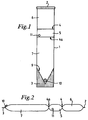
- the dispensing device in figures 1 and 2 is formed from a clear, plastics tube, e.g. a polypropylene.
- the tube is clamped and heated at its ends in order to form permanent seals 2 and 3.
- the tube indicated by reference 1 in the drawings, is provided with temporary seals 4, 4a which define an intermediate compartment 5.
- a first outer compartment 6 is defined between end 2 and temporary seal 4, and a second outer compartment 7 is defined between temporary seal 4 and end 3 of the device.
- the compartment 6 contains a powdered drug or pharmaceutical and compartment 7 contains a liquid, e.g. water, normal saline or glucose.
- the sealed end 3 is shaped so that the compartment 7 terminates in a "V" shape 9.
- a circular disc 10 of the silicone rubber is affixed to the outside of tube 1 adjacent to the vertex of "V" part 9, and defines the locus of insertion of a syringe.
- a small ceramic bead 11 is present in intermediate compartment 5.
- the bead carries an indicator which changes colour in the presence of a liquid from compartment 7, and is constructed of a buoyant material.
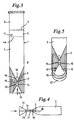
- FIGs 3 and 4 The embodiment shown in Figures 3 and 4 is generally similar to that of Figures 1 and 2, except that the provisions for inserting a syringe needle take an alternative form.
- the "V"-shaped end 9 of compartment 7 terminates, at the vertex of the "V", in a needle entry device 12.
- This is formed of a relatively rigid plastics material, and comprises a funnel-shaped outer part 13 and a tubular part 14.
- the tubular part defines a channel 15 through which the needle of a syringe passes to gain entry to compartment 7.
- Tubular portion 14 extends into compartment 7 and is in communication with the liquid material contained in that compartment via hole 16 in the side of the hard plastics material.
- a rubber seal 17 is positioned within channel 15 and prevents egress of liquid material from compartment 7.
- FIG. 5 a variant of the structure of Figure 3 is shown.
- entry to the needle entry device 13 is protected by means of a temporary heat seal 19 formed between two flaps of plastics material which constitute an extension of the tubular device 1 beyond the limits of end seal 3.
- the lowermost portions 20 of these two plastics flaps are left unsealed, so that the two flaps can readily be parted and then pulled to release temporary seal 19 and to permit access to channel 15.
- the intermediate compartment 5 of a device in accordance with this invention is surrounded by a soft, clear plastics sheath 21. This provides some protection for temporary seals 4 and 4a, and also assists the user of the device when the temporary seals are to he broken.
- a foil laminate 22 encapsulates the compartment 5, in order to protect the material contained in that compartment from environmental factors such as light and oxygen.
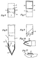
- a rigid plastics end piece 23 is provided in the interior of the device at the "V"-shaped end 9 of compartment 7.
- a silicone rubber pad 10 is affixed to the exterior of tube 1 adjacent to a hole 24 in end piece 23. This arrangement permits access of a needle 25 which pierces rubber pad 10 and passes through hole 24 into the interior of compartment 7. End piece 23 prevents the needle piercing end section 9 of compartment 7.
- Figures 9 - 14 illustrate alternative arrangements whereby the end of compartment 7 may be protected from unwanted damage when a needle such as 25 is inserted into the device.
- a hard, plastics sleeve 25 is fitted over the exterior of tube 1 in the vicinity of compartment 7 and end seal 3.
- the needle entry point is defined by rubber pad 10 which, as in the case of Figure 8, is adjacent to an opening 26 in the hard sleeve 25.
- Figure 11 shows a variant which is applicable to any of the embodiments of the invention in which a rubber pad 10 is employed.
- a peel-off protective strip 27 is applied to the exterior face of pad 10.
- a hard plastics clip 28 fits over part of end seal 3 and "V"-shaped end section 9 of compartment 7.
- a rubber pad 10 is again fixed to the exterior of clip 28 adjacent to an opening 29 in clip 28 to permit needle access.
- a rubber pad 10 is fixed to the outside wall of compartment 7 adjacent to end seal 3, and on the opposed region of compartment 7 there is provided a hard plastics disc 30 heat sealed onto the soft plastics material of tube 1.
- Disc 30 provides a protective barrier preventing penetration of tube 1 by a needle inserted through pad 10 into compartment 7.
- the dispensing device has two generally linear end seals 2 and 3', and temporary seals 4' and 4a'. These temporary seals are oblique with respect to the longitudinal axis of the device, and extend from end seal 2 to the wall of tube 1. With the illustrated arrangement, compartment 7 is very much larger than compartment 6. This arrangement is particularly suitable for dispensing relatively large volumes of solution.
- the device is adapted to enable withdrawal of solution therefrom using a syringe with or without a needle.
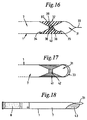
- the tube 1 has a fourth compartment 31 which is defined by a rubber bung 32 at one end and a temporary seal 33 at the other end.
- the bung 32 defines a first "V"-shape 34 and a second "V"-shape 35. The latter allows the guidance of the syringe towards the valve 36.
- This valve 36 comprises two flaps 37 and 38, and two corresponding recesses 39 and 40.
- a syringe may be inserted into the valve 36, forcing flaps 37 and 38 apart and into their corresponding recesses 39 and 40, respectively, thus facilitating entry into the compartment 7 and enabling extraction of the solution contained therein.
- the fourth compartment 31 is defined at one end by a temporary seal 33, as before, and at the other by a constriction 41.
- This constriction 41 defines a channel through which the lumen of a syringe may be inserted. This channel is sealed by a temporary seal 42 which is broken when the lumen of a syringe is inserted into the channel.
- the constriction 41 forms a "V"-shape which guides the syringe towards the temporary seal 42.
- the temporary seal 33 is broken by hand, the syringe is inserted into the compartment 31 and is guided towards the temporary seal 42 by means of the "V"-shape formed by the constriction 41.
- the temporary seal 42 is broken by the end of the syringe and diluant from compartment 7 may be withdrawn.
- Figure 18 illustrates a further form of this embodiment, wherein the fourth compartment 31 has a permanently sealed area 43 which forms a flattened area which allows the device 1 to be held between the first finger and thumb while the needle and/or syringe is inserted into the entry channel.
- the device may be constructed of annularly co-extruded polymers, the outer of these polymers being relatively more resilient than the inner.
- the outer polymer is of a different colour to that of the inner polymer, thereby allowing removal of the outer layer to generate indicia, for example, the name of the pharmaceutical and its dosage. This removal can, for example, be achieved by means of a laser.
- the temporary seal 33 may have a pressure and/or moisture sensitive indicator between the two flaps of plastic which are sealed by temporary seal 33 to show accidental opening.
Landscapes
- Engineering & Computer Science (AREA)
- Mechanical Engineering (AREA)
- Medical Preparation Storing Or Oral Administration Devices (AREA)
- Electrical Discharge Machining, Electrochemical Machining, And Combined Machining (AREA)
- Package Specialized In Special Use (AREA)
- Lining Or Joining Of Plastics Or The Like (AREA)
- Details Of Rigid Or Semi-Rigid Containers (AREA)
Claims (31)
- Einrichtung, umfassend einen im allgemeinen zylindrischen Kunststoffbehälter (1), der am einen Ende mit einem Dauerverschluß (2) und am anderen Ende mit einem vorläufigen Verschluß oder einem Dauerverschluß (3) verschlossen ist, wobei der Behälter vorläufige Verschlüsse (4, 4a) aufweist, die ihn in mindestens drei Abteilungen einschließlich einer Zwischenabteilung (5) unterteilen, die an ihren beiden Seiten Abteilungen (6, 7) hat,
worin die eine Abteilung (6) der Abteilungen zu beiden Seiten der Zwischenabteilung (5) ein erstes Material und die andere Abteilung (7) ein zweites Material enthält, in dem das erste Material vor Gebrauch zu verteilen oder aufzulösen ist, die Zwischenabteilung (5) weder das erste noch das zweite Material enthält und die vorläufigen Verschlüsse (4, 4a) so angeordnet sind, daß sie durch Fingerdruck geöffnet werden können, um eine Verbindung zwischen den Abteilungen (5, 6, 7) zu gestatten, wodurch das Mischen des ersten und des zweiten Materials ermöglicht wird, dadurch gekennzeichnet,
daß die Zwischenabteilung (5) eine Perle (11) enthält, die beim Mischen des ersten und zweiten Materials hilft, nachdem die vorläufigen Verschlüsse (4, 4a) geöffnet wurden, die die Zwischenabteilung (5) bestimmen. - Einrichtung nach Anspruch 1, dadurch gekennzeichnet, daß das erste Material ein Pulver und das zweite Material eine Flüssigkeit ist.
- Einrichtung nach Anspruch 2, dadurch gekennzeichnet, daß das Pulver ein abgewogenes Quantum eines pulverförmigen Arzneimittels ist.
- Einrichtung nach Anspruch 2 oder 3, dadurch gekennzeichnet, daß die Flüssigkeit destilliertes Wasser, blutisotone Lösung oder Glucoselösung ist.
- Einrichtung nach Anspruch 2, 3 oder 4, dadurch gekennzeichnet, daß die Perle (11) auf ihrer Oberfläche einen Indikator hat, der für die Flüssigkeit empfindlich ist, oder daß die Perle (11) damit imprägniert ist.
- Einrichtung nach irgendeinem vorhergehenden Anspruch, dadurch gekennzeichnet, daß die Perle (11) aus Keramik besteht.
- Einrichtung nach irgendeinem der Ansprüche 1 bis 6, dadurch gekennzeichnet, daß die Perle (11) aus einem schwimmfähigen Material aufgebaut ist.
- Einrichtung nach irgendeinem vorhergehenden Anspruch, dadurch gekennzeichnet, daß die Perle (11) eine konische, sphärische, zylindrische, pyramidale oder doppelpyramidale Form hat.
- Einrichtung nach irgendeinem vorhergehenden Anspruch, dadurch gekennzeichnet, daß mindestens ein Ende der Einrichtung mit einem dauerhaften Heißverschluß verschlossen ist.
- Einrichtung nach irgendeinem vorhergehenden Anspruch, dadurch gekennzeichnet, daß ein Dauerverschluß (3) am einen Ende der Einrichtung ein "v-förmiges" Ende (9) der benachbarten Abteilung (7) bestimmt.
- Einrichtung nach irgendeinem vorhergehenden Anspruch, dadurch gekennzeichnet, daß die Einrichtung auf ihrer Außenseite ein kleines Kissen (10) trägt, das eine Soll-Einstichstelle bestimmt und dabei hilft, eine Dichtung um die Wandung einer Nadel herum bereitzustellen, während die Lösung oder Suspension aus dem ersten und zweiten Material entnommen wird.
- Einrichtung nach Anspruch 11, dadurch gekennzeichnet, daß über dem Kissen (10) ein abziehbarer Schutzstreifen (27) befestigt ist.
- Einrichtung nach irgendeinem der Ansprüche 1 bis 8, dadurch gekennzeichnet, daß die Einrichtung an einem ihrer Enden einen Einlaßkanal für eine Spritze oder eine Nadel enthält.
- Einrichtung nach Anspruch 13, dadurch gekennzeichnet, daß der Einlaßkanal einen Trichter (13, 41) umfaßt, der in seinem Hals einen vorläufigen Verschluß (17, 42) enthält, wobei die Wandung einer Nadel den Verschluß (17, 42) bei Gebrauch durchstößt.
- Einrichtung nach Anspruch 13, dadurch gekennzeichnet, daß der Einlaßkanal einen Trichter (35) umfaßt, der in seinem Hals ein Ventil (36) enthält, wobei die Wandung einer Nadel oder Spritze das Ventil (36) bei Gebrauch durchstößt.
- Einrichtung nach Anspruch 14 oder 15, dadurch gekennzeichnet, daß der Trichter (13, 36) aus einem Kunststoff- oder Gummipreßmaterial aufgebaut ist.
- Einrichtung nach Anspruch 13, 14, 15 oder 16, dadurch gekennzeichnet, daß der Einlaßkanal durch einen vorläufigen Heißverschluß (19, 33) geschützt wird, der zwischen Klappen aus Kunststoffmaterial an dem einen Ende der Spendeeinrichtung liegt.
- Einrichtung nach Anspruch 17, dadurch gekennzeichnet, daß der vorläufige Heißverschluß (19, 33) einen druckund/oder feuchtigkeitsempfindlichen Indikator zwischen den Klappen aus Kunststoffmaterial enthält.
- Einrichtung nach irgendeinem der Ansprüche 13 bis 18, dadurch gekennzeichnet, daß der Einlaßkanal einen im wesentlichen flachen Bereich (43) aufweist, um das Halten der Einrichtung zu unterstützen.
- Einrichtung nach irgendeinem vorhergehenden Anspruch, dadurch gekennzeichnet, daß die Außenseite der Einrichtung in der Nähe der Zwischenabteilung von einer Hülle (21) aus Kunststoffmaterial umgeben ist.
- Einrichtung nach irgendeinem vorhergehenden Anspruch, dadurch gekennzeichnet, daß die Abteilung (6) der Einrichtung, die das erste Material enthält, von einer Folienschicht (22) umgeben ist.
- Einrichtung nach irgendeinem vorhergehenden Anspruch, dadurch gekennzeichnet, daß die vorläufigen Verschlüsse (4, 4a), die die Zwischenabteilung (5) bestimmen, geradlinig sind und senkrecht zur Längsachse der Einrichtung angeordnet sind.
- Einrichtung nach irgendeinem der Ansprüche 1 bis 21, dadurch gekennzeichnet, daß die vorläufigen Verschlüsse (4, 4a), die die Zwischenabteilung (5) bestimmen, gekrümmt aufgebaut sind oder bezüglich der Längsachse der Einrichtung schräg angebracht sind.
- Einrichtung nach irgendeinem vorhergehenden Anspruch, dadurch gekennzeichnet, daß der Kunststoffbehälter (1) aus zwei ringförmigen, gemeinsam extrudierten Polymeren besteht, wobei das innere der beiden Polymere relativ weniger elastisch ist als das äußere.
- Einrichtung nach Anspruch 24, dadurch gekennzeichnet, daß jedes der Polymere eine unterschiedliche Farbe hat.
- Einrichtung nach Anspruch 25, dadurch gekennzeichnet, daß vorbestimmte Abschnitte des äußeren Polymers entfernt sind, um Kennzeichnungen zu erzeugen.
- Verfahren zum Herstellen einer Einrichtung nach Anspruch 1, umfassend
das Formen des Behälters (1) durch Extrudieren;
das dauerhafte Verschließen eines Behälterendes;
das Einlagern des ersten oder zweiten Materials in den Behälter (1) und das Verschließen des Materials darin mit Hilfe eines vorläufigen Verschlusses (4);
das Einlagern der Perle (11) in den Behälter (1) und das Verschließen der Perle (11) darin mit Hilfe eines weiteren vorläufigen Verschlusses (4a), wobei die Zwischenabteilung (5) ausgebildet wird;
das Einlagern des zweiten oder ersten Materials in den Behälter (1) und das Verschließen des Materials darin mit Hilfe eines vorläufigen oder dauerhaften Verschlusses (3),
wobei die vorläufigen Verschlüsse (4, 4a) durch das Anwenden von Wärme auf gegenüberliegende Seiten des Behälters (1) gebildet werden, um die Seiten des Behälters (1) zusammenzukleben, ohne jedoch eine dauerhafte Verbindung zu bilden. - Verfahren nach Anspruch 27, wobei ein Verschluß oder beide Verschlüsse (2, 3) an den Enden der Einrichtung durch das Anwenden von Druck und Wärme auf gegenüberliegende Seiten des Behälters gebildet wird bzw. werden, um einen dauerhaften Heißverschluß zu bilden.
- Verfahren nach Anspruch 27 oder Anspruch 28, wobei die vorläufigen Verschlüsse so ausgebildet und angeordnet sind, daß sie durch Fingerdruck geöffnet werden können.
- Verfahren nach Anspruch 27, 28 oder 29, geeignet zum Verpacken eines pharmazeutischen Materials, wobei eines der ersten und zweiten Materialien ein pharmazeutisches Material ist und das andere der ersten und zweiten Materialien ein Verdünnungsmittel für das pharmazeutische Material ist.
- Verfahren zum Ausgeben eines pharmazeutischen Materials, das gemäß Anspruch 29 verpackt ist, wenn abhängig von Anspruch 29, umfassend das Öffnen jedes vorläufigen Verschlusses (4, 4a), der die Zwischenabteilung (5) bestimmt, die die Perle (11) enthält, wobei Fingerdruck auf die Kanten des Verschlusses ausgeübt, der Behälter (1) geschüttelt und die entstehende Lösung, Dispersion oder Suspension herausgezogen wird.
Applications Claiming Priority (3)
| Application Number | Priority Date | Filing Date | Title |
|---|---|---|---|
| GB898911878A GB8911878D0 (en) | 1989-05-24 | 1989-05-24 | Mixing device |
| GB8911878 | 1989-05-24 | ||
| PCT/GB1990/000777 WO1990014293A1 (en) | 1989-05-24 | 1990-05-17 | Mixing device |
Publications (2)
| Publication Number | Publication Date |
|---|---|
| EP0473666A1 EP0473666A1 (de) | 1992-03-11 |
| EP0473666B1 true EP0473666B1 (de) | 1995-08-16 |
Family
ID=10657246
Family Applications (1)
| Application Number | Title | Priority Date | Filing Date |
|---|---|---|---|
| EP90908289A Expired - Lifetime EP0473666B1 (de) | 1989-05-24 | 1990-05-17 | Mischvorrichtung |
Country Status (7)
| Country | Link |
|---|---|
| US (1) | US5207320A (de) |
| EP (1) | EP0473666B1 (de) |
| JP (1) | JPH04505718A (de) |
| AT (1) | ATE126497T1 (de) |
| DE (1) | DE69021726D1 (de) |
| GB (1) | GB8911878D0 (de) |
| WO (1) | WO1990014293A1 (de) |
Families Citing this family (49)
| Publication number | Priority date | Publication date | Assignee | Title |
|---|---|---|---|---|
| US5352036A (en) * | 1992-09-23 | 1994-10-04 | Habley Medical Technology Corporation | Method for mixing and dispensing a liquid pharmaceutical with a miscible component |
| US5507133A (en) * | 1994-02-07 | 1996-04-16 | University Of Hawaii | Inoculant method and apparatus |
| US5616337A (en) * | 1995-01-30 | 1997-04-01 | Genta Incorporated | Unit dose skin care package |
| US5961210A (en) * | 1997-01-24 | 1999-10-05 | Mccardel; Brian R. | Bone cement preparation device, and methods of constructing and utilizing same |
| DE19718543A1 (de) * | 1997-05-02 | 1998-11-05 | Braun Melsungen Ag | Flexibler, dichter Mehrkammerbeutel |
| US20050194060A1 (en) * | 2004-03-03 | 2005-09-08 | Vincent Houwaert | Peelable seal closure assembly |
| US7678097B1 (en) | 1999-11-12 | 2010-03-16 | Baxter International Inc. | Containers and methods for manufacturing same |
| US6758593B1 (en) * | 2000-10-09 | 2004-07-06 | Levtech, Inc. | Pumping or mixing system using a levitating magnetic element, related system components, and related methods |
| US6434913B1 (en) * | 2000-09-15 | 2002-08-20 | Thomas Hatch | Single-use syringe |
| SE0201330D0 (sv) * | 2002-04-30 | 2002-04-30 | Astra Tech Ab | Catheter assembly |
| US8590282B2 (en) | 2002-09-19 | 2013-11-26 | Poppack, Llc | Package with unique opening device and method for opening package |
| US7306371B2 (en) | 2004-12-14 | 2007-12-11 | Poppack, Llc | Access structure with bursting detonator for opening a sealed package |
| US7175614B2 (en) | 2002-10-17 | 2007-02-13 | Baxter International Inc. | Peelable seal |
| EP1565257B1 (de) * | 2002-11-20 | 2007-01-10 | Unilever N.V. | Vorrichtung und verfahren zum mischen von komponenten |
| JP4800953B2 (ja) * | 2003-05-15 | 2011-10-26 | コムキャスト ケーブル ホールディングス,エルエルシー | 映像再生方法およびシステム |
| US20040232152A1 (en) * | 2003-05-21 | 2004-11-25 | Arndt Schimmelmann | Safety glass break-seal vessel |
| US20050228216A1 (en) * | 2004-04-08 | 2005-10-13 | Vries Jan A D | Method for treating gastroesophageal reflux disease |
| US8177740B1 (en) | 2004-06-24 | 2012-05-15 | Kimberly-Clark Worldwide, Inc. | Medicinal liquid infuser with integral agitator means |
| AU2006316501A1 (en) * | 2005-11-22 | 2007-05-31 | Nestec S.A. | Easily dispersible lipidic phase |
| US20070286535A1 (en) * | 2006-04-10 | 2007-12-13 | Perell William S | Shaped breaching bubble with inward incursion breaching focus |
| US7644821B2 (en) * | 2006-04-10 | 2010-01-12 | Poppack, Llc | Sealed product delivery unit with rupturing pump |
| US7909165B2 (en) * | 2006-04-10 | 2011-03-22 | Poppack, Llc | System for delivering sequential components |
| US8181818B2 (en) * | 2006-04-11 | 2012-05-22 | Poppack, Llc | Secure container with pressure responsive conduit for closure disruption |
| US20070235357A1 (en) * | 2006-04-11 | 2007-10-11 | Perell William S | Edge voids in a wrapped container for creating loose tear-away material |
| US8328017B2 (en) * | 2006-04-11 | 2012-12-11 | Poppack, Llc | User inflated breachable container, and method |
| US9004761B2 (en) * | 2006-05-01 | 2015-04-14 | Baxter International Inc. | Multiple chamber container with mistake proof administration system |
| US7757893B2 (en) * | 2006-06-26 | 2010-07-20 | Poppack Llc | Dispersing bubble with compressible transport fluid and method |
| US8684601B2 (en) * | 2007-03-02 | 2014-04-01 | Poppack, Llc | Storage apparatus with a breachable flow conduit for discharging a fluid stored therein |
| BRPI0821460A2 (pt) | 2007-12-31 | 2015-06-16 | Poppack Llc | Recipiente de armazenamento rígido com bolha de perímetro que pode ser rompida |
| CN101990514B (zh) * | 2008-01-09 | 2012-05-09 | 波普帕克有限公司 | 具有粘附关闭阀的倾倒通道以及锁闭泡形件 |
| US20100150481A1 (en) * | 2008-12-17 | 2010-06-17 | Perell Willaim S | Package for consumer products |
| ES2355343B1 (es) * | 2008-12-26 | 2012-03-07 | Ainia-Asociación De Investigación De La Industria Agroalimentaria | Envase para productos de preparación extempor�?nea. |
| WO2010109610A1 (ja) * | 2009-03-25 | 2010-09-30 | 株式会社モリモト医薬 | 医薬組成物容器 |
| WO2010109612A1 (ja) * | 2009-03-25 | 2010-09-30 | 株式会社モリモト医薬 | 医薬組成物容器 |
| US20100278462A1 (en) * | 2009-05-01 | 2010-11-04 | Poppack, Llc | Package With One or More Access Points For Breaking One or More Seals and Accessing the Contents of the Package |
| US20110103714A1 (en) * | 2009-09-18 | 2011-05-05 | Mark Steele | Package with pressure activated expansion chamber |
| US9365339B2 (en) | 2010-02-11 | 2016-06-14 | Poppack, Llc | Package with unique opening device and process for forming package |
| US20110200275A1 (en) * | 2010-02-12 | 2011-08-18 | Poppack, Llc | Package containing a breachable bubble in combination with a closure device |
| WO2011122640A1 (ja) * | 2010-03-29 | 2011-10-06 | 株式会社モリモト医薬 | 経口摂取用の医薬組成物容器 |
| US20120109098A1 (en) * | 2010-10-28 | 2012-05-03 | Tyco Healthcare Group Lp. | Applicator Tips Having Mixing Ball |
| US8708195B1 (en) * | 2011-04-04 | 2014-04-29 | Lindsay Duran | Bifurcated alcoholic beverage dispenser and associated use thereof |
| US20130336085A1 (en) * | 2012-06-18 | 2013-12-19 | Michael Drake | Method and Apparatus for Mixing Drinks |
| FR2992634B1 (fr) * | 2012-06-28 | 2014-07-11 | Physidia | Dispositif pour la detection de la rupture de la ou des parois de separation des compartiments d'une poche |
| CA2843096A1 (en) * | 2013-02-20 | 2014-08-20 | James P. Knutzon | Multi-compartment bag and method of making same |
| US20150117798A1 (en) * | 2013-10-24 | 2015-04-30 | Rama Taghvai | Convertible Multi-Compartment Polymeric Storage Bag |
| US9775946B2 (en) * | 2016-02-11 | 2017-10-03 | Bioq Pharma Inc. | Unified drug mixer and dispenser |
| US11724866B2 (en) | 2019-02-15 | 2023-08-15 | Poppack Llc | Package with unique opening device and method of producing packages |
| US11383909B2 (en) | 2019-02-27 | 2022-07-12 | Poppack Llc | Easy to open package with controlled dispensing device |
| CN114904452A (zh) * | 2021-02-08 | 2022-08-16 | 中国人民解放军海军军医大学第一附属医院 | 一种药剂和溶剂的无菌混合装置及其应用 |
Family Cites Families (20)
| Publication number | Priority date | Publication date | Assignee | Title |
|---|---|---|---|---|
| GB670314A (en) * | 1947-12-24 | 1952-04-16 | Felix Meyer | Improvements in or relating to ampoules for medical purposes |
| US2487236A (en) * | 1947-12-31 | 1949-11-08 | Alvin A Greenberg | Compartmented container having a rupturable partition |
| US2660171A (en) * | 1950-12-07 | 1953-11-24 | Jr Fairleigh S Dickinson | Vial |
| FR1054170A (fr) * | 1952-08-19 | 1954-02-09 | Récipients destinés à la conservation de produits différents | |
| FR1528920A (fr) * | 1967-05-05 | 1968-06-14 | Cartouche à capacités multiples pour conditionnement de substances prédosées | |
| US3451540A (en) * | 1967-12-12 | 1969-06-24 | Pennsalt Chemicals Corp | Disposable mixing capsule |
| US3478871A (en) * | 1968-04-29 | 1969-11-18 | Kleer Vu Ind Inc | Burst package with fold seal |
| US3674028A (en) * | 1969-06-04 | 1972-07-04 | Ims Ltd | Multi-mix |
| US3608709A (en) * | 1969-09-08 | 1971-09-28 | Wayne Rogers V | Multiple compartment package |
| US3749620A (en) * | 1969-11-20 | 1973-07-31 | American Cyanamid Co | Package for plural reactable components with rupturable ultrasonic seal |
| US3847274A (en) * | 1971-04-21 | 1974-11-12 | Propper Mfg Co Inc | Capillary tube dispensing vial and stand |
| FR2188565A5 (de) * | 1972-06-13 | 1974-01-18 | Semco Emballage Conditio | |
| US4197943A (en) * | 1978-08-14 | 1980-04-15 | Weikel Maurice M | Dental alloy container |
| US4402402A (en) * | 1981-10-14 | 1983-09-06 | Pike Brian R | Barrier seal multiple-compartment package |
| US4496046A (en) * | 1983-09-15 | 1985-01-29 | Baxter Travenol Laboratories, Inc. | Multiple chamber container with inner diaphragm and intermediate chamber |
| US4602910A (en) * | 1984-02-28 | 1986-07-29 | Larkin Mark E | Compartmented flexible solution container |
| US4608043A (en) * | 1984-06-22 | 1986-08-26 | Abbott Laboratories | I.V. fluid storage and mixing system |
| US4591357A (en) * | 1985-09-27 | 1986-05-27 | Sneider Vincent R | Container for drug isolation, storage and subsequent mixing |
| US4632244A (en) * | 1986-02-19 | 1986-12-30 | Boris Landau | Multiple chamber flexible container |
| US5154321A (en) * | 1991-01-15 | 1992-10-13 | John Shomer | Dispensing container for multi-component curable compositions |
-
1989
- 1989-05-24 GB GB898911878A patent/GB8911878D0/en active Pending
-
1990
- 1990-05-17 US US07/776,401 patent/US5207320A/en not_active Expired - Fee Related
- 1990-05-17 AT AT90908289T patent/ATE126497T1/de not_active IP Right Cessation
- 1990-05-17 EP EP90908289A patent/EP0473666B1/de not_active Expired - Lifetime
- 1990-05-17 JP JP2507990A patent/JPH04505718A/ja active Pending
- 1990-05-17 WO PCT/GB1990/000777 patent/WO1990014293A1/en not_active Ceased
- 1990-05-17 DE DE69021726T patent/DE69021726D1/de not_active Expired - Lifetime
Also Published As
| Publication number | Publication date |
|---|---|
| WO1990014293A1 (en) | 1990-11-29 |
| ATE126497T1 (de) | 1995-09-15 |
| EP0473666A1 (de) | 1992-03-11 |
| JPH04505718A (ja) | 1992-10-08 |
| US5207320A (en) | 1993-05-04 |
| DE69021726D1 (de) | 1995-09-21 |
| GB8911878D0 (en) | 1989-07-12 |
Similar Documents
| Publication | Publication Date | Title |
|---|---|---|
| US5207320A (en) | Compartmented mixing device with bead | |
| US5161681A (en) | Safety container for hypodermic syringes | |
| US4667837A (en) | Tamper proof cap | |
| US4645073A (en) | Anti-contamination hazardous material package | |
| US3938520A (en) | Transfer unit having a dual channel transfer member | |
| US4643309A (en) | Filled unit dose container | |
| US20030187403A1 (en) | Tamper evident overap for a container | |
| US6398031B1 (en) | Vial for packaging a liquid for medical use | |
| US4581023A (en) | Hypodermic syringe assembly | |
| US20030032923A1 (en) | Tamper evident syringe barrel | |
| US20060175279A1 (en) | Vial for filling a syringe | |
| EP0687477A1 (de) | Eine arznei enthaltende spritze | |
| US10220156B2 (en) | Single use injector | |
| SK144798A3 (en) | Two-chamber cartridge for propellant-free metered aerosols | |
| KR20110040987A (ko) | 둘 이상의 성분을 혼합하기 위한 제약품 용기 시스템에 이용하기 위한 사전충전된 용기 삽입체 | |
| EP1169075A1 (de) | Spritze mit originalitätsicherung | |
| JPS58173549A (ja) | シ−ル破れ探知具 | |
| US5873860A (en) | Injection device | |
| US20190167920A1 (en) | Single Use Injector | |
| US2856929A (en) | Plastic container | |
| US4020836A (en) | Apparatus for medical injections | |
| US1668588A (en) | Hypodermic syringe | |
| JP4567274B2 (ja) | 薬液既充填小型注射器の製造方法 | |
| EP1435893B1 (de) | Sicherheitsverpackung für eine flasche für medizinische anwendungen | |
| GB2211104A (en) | All-in-one drug/substance and solvent package for injection |
Legal Events
| Date | Code | Title | Description |
|---|---|---|---|
| PUAI | Public reference made under article 153(3) epc to a published international application that has entered the european phase |
Free format text: ORIGINAL CODE: 0009012 |
|
| 17P | Request for examination filed |
Effective date: 19911216 |
|
| AK | Designated contracting states |
Kind code of ref document: A1 Designated state(s): AT BE CH DE DK ES FR GB IT LI LU NL SE |
|
| 17Q | First examination report despatched |
Effective date: 19921229 |
|
| RIN1 | Information on inventor provided before grant (corrected) |
Inventor name: ALLEN, NICHOLAS JOHN |
|
| RAP1 | Party data changed (applicant data changed or rights of an application transferred) |
Owner name: HEATHCOTE-LUNDE LIMITED |
|
| GRAA | (expected) grant |
Free format text: ORIGINAL CODE: 0009210 |
|
| AK | Designated contracting states |
Kind code of ref document: B1 Designated state(s): AT BE CH DE DK ES FR GB IT LI LU NL SE |
|
| PG25 | Lapsed in a contracting state [announced via postgrant information from national office to epo] |
Ref country code: IT Free format text: LAPSE BECAUSE OF FAILURE TO SUBMIT A TRANSLATION OF THE DESCRIPTION OR TO PAY THE FEE WITHIN THE PRE;WARNING: LAPSES OF ITALIAN PATENTS WITH EFFECTIVE DATE BEFORE 2007 MAY HAVE OCCURRED AT ANY TIME BEFORE 2007. THE CORRECT EFFECTIVE DATE MAY BE DIFFERENT FROM THE ONE RECORDED.SCRIBED TIME-LIMIT Effective date: 19950816 Ref country code: CH Effective date: 19950816 Ref country code: NL Free format text: LAPSE BECAUSE OF FAILURE TO SUBMIT A TRANSLATION OF THE DESCRIPTION OR TO PAY THE FEE WITHIN THE PRESCRIBED TIME-LIMIT Effective date: 19950816 Ref country code: FR Free format text: THE PATENT HAS BEEN ANNULLED BY A DECISION OF A NATIONAL AUTHORITY Effective date: 19950816 Ref country code: DK Effective date: 19950816 Ref country code: LI Effective date: 19950816 Ref country code: ES Free format text: THE PATENT HAS BEEN ANNULLED BY A DECISION OF A NATIONAL AUTHORITY Effective date: 19950816 Ref country code: AT Effective date: 19950816 Ref country code: BE Effective date: 19950816 |
|
| REF | Corresponds to: |
Ref document number: 126497 Country of ref document: AT Date of ref document: 19950915 Kind code of ref document: T |
|
| REF | Corresponds to: |
Ref document number: 69021726 Country of ref document: DE Date of ref document: 19950921 |
|
| PG25 | Lapsed in a contracting state [announced via postgrant information from national office to epo] |
Ref country code: SE Effective date: 19951116 |
|
| PG25 | Lapsed in a contracting state [announced via postgrant information from national office to epo] |
Ref country code: DE Effective date: 19951117 |
|
| EN | Fr: translation not filed | ||
| NLV1 | Nl: lapsed or annulled due to failure to fulfill the requirements of art. 29p and 29m of the patents act | ||
| PGFP | Annual fee paid to national office [announced via postgrant information from national office to epo] |
Ref country code: GB Payment date: 19960514 Year of fee payment: 7 |
|
| PG25 | Lapsed in a contracting state [announced via postgrant information from national office to epo] |
Ref country code: LU Free format text: LAPSE BECAUSE OF NON-PAYMENT OF DUE FEES Effective date: 19960531 |
|
| PLBE | No opposition filed within time limit |
Free format text: ORIGINAL CODE: 0009261 |
|
| STAA | Information on the status of an ep patent application or granted ep patent |
Free format text: STATUS: NO OPPOSITION FILED WITHIN TIME LIMIT |
|
| 26N | No opposition filed | ||
| PG25 | Lapsed in a contracting state [announced via postgrant information from national office to epo] |
Ref country code: GB Effective date: 19970517 |
|
| GBPC | Gb: european patent ceased through non-payment of renewal fee |
Effective date: 19970517 |