EP0473834A1 - Système de commande d'un poste d'aiguillage électronique organisé suivant le principe de commande à ordinateur local - Google Patents
Système de commande d'un poste d'aiguillage électronique organisé suivant le principe de commande à ordinateur local Download PDFInfo
- Publication number
- EP0473834A1 EP0473834A1 EP90117294A EP90117294A EP0473834A1 EP 0473834 A1 EP0473834 A1 EP 0473834A1 EP 90117294 A EP90117294 A EP 90117294A EP 90117294 A EP90117294 A EP 90117294A EP 0473834 A1 EP0473834 A1 EP 0473834A1
- Authority
- EP
- European Patent Office
- Prior art keywords
- computer
- control
- messages
- message
- computers
- Prior art date
- Legal status (The legal status is an assumption and is not a legal conclusion. Google has not performed a legal analysis and makes no representation as to the accuracy of the status listed.)
- Granted
Links
- 238000000034 method Methods 0.000 claims abstract description 29
- 101100386054 Saccharomyces cerevisiae (strain ATCC 204508 / S288c) CYS3 gene Proteins 0.000 claims abstract description 15
- 101150035983 str1 gene Proteins 0.000 claims abstract description 15
- 238000012544 monitoring process Methods 0.000 claims abstract description 14
- 230000005540 biological transmission Effects 0.000 claims description 8
- 238000011156 evaluation Methods 0.000 abstract description 2
- 230000011664 signaling Effects 0.000 description 5
- 230000004888 barrier function Effects 0.000 description 2
- 238000013461 design Methods 0.000 description 2
- 230000007257 malfunction Effects 0.000 description 2
- 238000004886 process control Methods 0.000 description 2
- 238000012545 processing Methods 0.000 description 2
- 230000006978 adaptation Effects 0.000 description 1
- 230000000903 blocking effect Effects 0.000 description 1
- 230000001934 delay Effects 0.000 description 1
- 238000010586 diagram Methods 0.000 description 1
- 230000000694 effects Effects 0.000 description 1
- 230000007717 exclusion Effects 0.000 description 1
- 238000012986 modification Methods 0.000 description 1
- 230000004048 modification Effects 0.000 description 1
Images
Classifications
-
- B—PERFORMING OPERATIONS; TRANSPORTING
- B61—RAILWAYS
- B61L—GUIDING RAILWAY TRAFFIC; ENSURING THE SAFETY OF RAILWAY TRAFFIC
- B61L21/00—Station blocking between signal boxes in one yard
-
- B—PERFORMING OPERATIONS; TRANSPORTING
- B61—RAILWAYS
- B61L—GUIDING RAILWAY TRAFFIC; ENSURING THE SAFETY OF RAILWAY TRAFFIC
- B61L19/00—Arrangements for interlocking between points and signals by means of a single interlocking device, e.g. central control
- B61L19/06—Interlocking devices having electrical operation
Definitions
- the invention relates to a device according to the preamble of claim 1.
- a device is known from Signal and Wire 81 (1989) 5, pages 95 to 102.
- the guideway elements are to be connected on the input side to the output of one or the other positioning computer depending on whether one or the other associated positioning computer is operational; this must be done without retroactive effect and is carried out via exclusion switching means.
- a further disadvantage is that the previously inactive control computer only becomes aware of the actual states of the respectively connected route elements after the switchover. This unnecessarily delays process control.
- Another disadvantage of the known device can be seen in the fact that at least the feedback of the operating states to the control computer takes place only in one channel.
- the object of the invention is to provide a device according to the preamble of claim 1, which is flexible in terms of its redundancy design. Any malfunctions in the transmission of commands and messages should be recognizable as quickly as possible when they occur and should enable the controlling area computer to react immediately and appropriately to the malfunction that has occurred.
- the invention solves this problem by the characterizing features of claim 1.
- the continuous reading of messages into the control computer in connection with the transmission of message releases allows faulty messages to be recognized immediately; reading the messages into two control computers in each case makes it possible to evaluate the messages transmitted via the other channel in the event of a fault in one transmission channel, without requiring any significant additional effort for switching the messages.
- the command route to the output switching means for the route elements is monitored by monitoring messages for the correct output of the commands. Only where redundant control of a process element is actually required, redundant control computer parts are provided for the command output to the route elements.
- Claim 2 denotes the representation of the messages and the associated message releases and their transmission to the control computer and the assignment of the messages to the releases.
- the area computer individually selects those message bits that were received without interference from the message bytes transmitted by two control computers.
- the overall message evaluation is only disrupted if the corresponding message bits are disrupted in both message bytes.
- Claim 4 indicates how the area computer derives the original messages from the messages and releases transmitted to it.
- Claim 5 includes the configuration of the device according to the invention with non-redundant control of a process element and claim 6 of its configuration with redundant control.
- Claim 7 designates the means for blocking an actuating computer as required, via which proper access to a process element to be controlled is no longer provided.
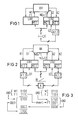
- Figure 1 shows schematically an area computer BR together with two control computers STR1 and STR2 for controlling a light signal S and other process elements of an interlocking, not shown in the drawing.
- the area computer and the two control computers represent only a small section of the control elements of an interlocking.
- the light signal is controlled in the command direction in a non-redundant manner exclusively via the control computer STR2. Redundancy is therefore not necessary because if the signal cannot be controlled via the control computer, the signal goes to a stop (safe state) and because this signal can be passed through by turning on the beacon or with a written command. The disruption that occurs does not make the adjacent section of the route generally impassable; Redundancy is therefore not absolutely necessary.
- the light signal is controlled via assigned actuators K2.1 and K2.2; K2.1 essentially contains the output gates of the control computer STR2 for the light signal, K2.2 essentially the adaptations for converting control instructions originating from the associated control computer into connection orders for the power switching means of the light signal.
- Monitoring messages Ü2 for identifying the respective switching state of the power switching means in the external control element are transmitted via the control computer STR2 to the area computer, which is then able to monitor the correct operation of the control elements.
- the respective operating state of the light signal is supplied in the form of operating state messages both to the signaling part M2.1 of the controlling control computer STR2 and to the signaling part M1.1 of a control computer STR1 provided for controlling other process elements.
- Both control computers independently check the transmitted messages for proper reception and transmit them separately to the controlling area computer BR. In doing so, they provide messages M1 and M2 with message releases F1 and F2, respectively, which indicate to the area computer whether the associated messages have been properly received or not. On the basis of the message releases sent to it, the area computer decides which of the two-channel messages sent to it are to be recognized as correct and which are not.
- each with a message release which characterizes the proper receipt of the message are read into one or the other processing channel of the area computer; If a message is only present on one message channel and has a positive message release, it is read into both processing channels of the area computer.
- Each message preferably consists of a bit of one or a different value and in the control computers, message bytes for transmission to the associated area computer are formed from the messages, possibly also from the messages of several controlled process elements.
- Each signal processor generates an enable bit with the value L if the message bit is received undisturbed and an enable bit with the value 0 if the message bit is disrupted. These bits are transferred to the area computer together with the associated message byte as the message enable byte.
- the area computer individually selects from the messages transmitted to it byte by byte by both actuating computers those bits to which message releases with the value L are assigned and discards all messages that are not provided with message releases of this value.
- FIG. 2 includes the use of the invention in the control of a guideway element for which redundancy is required both in the message and in the command direction.
- This switch must remain taxable, even if it can no longer be controlled by a control computer normally responsible for it.
- another control computer provided for this purpose jumps in, which previously has also been constantly supplied with the status messages from the switch.
- the switch W is usually controlled via the control computer STR1.
- the area computer BR supplies the Control computer STR1 with corresponding commands K1. These commands are transmitted via a computer-internal control part K1.1 to a computer-external control part K1.2, in which the commands are converted into switching orders for power switching devices for controlling the point machine A.
- the drive is supplied with power in a known manner, for example via four-wire lines from the control part K1.2 external to the computer.
- This control unit transmits monitoring messages Ü1 via the switching position of its power switching means to the control computer STR1, which either forwards these monitoring messages to the area computer BR or compares them beforehand with the command commands pending and forwards the comparison results to the area computer.
- the area computer recognizes from the monitoring messages whether the commands that it initiated are carried out or not. He only tries to access drive A via the control computer STR1, as long as the control computer sends him the appropriate monitoring messages regarding the correct output of commands. If these monitoring messages fail to appear, or if they show that correct command output is no longer possible, the control computer STR1 locks the command parts assigned to it against further exposure and informs the area computer of this. This then causes the drive to be controlled via the control computer STR2. For this purpose, it supplies the control computer with the corresponding commands K2, which are output to the drive via internal and external control parts K2.1 and K2.2. A constant monitoring of the command path up to the control part K2.2 external to the computer is also provided here, with corresponding monitoring messages Ü2 being sent to the control computer STR2 and from there directly or in a processed form to the area computer.
- the operating status messages of the switch are fed to the message parts M1.1 and M2.1 of the two control computers STR1 and STR2. There they are provided with message releases F1 and F2 and transmitted to the area computer BR. From the messages transmitted to it by the two control computers, the area computer selects those which are provided with message releases for the correct receipt of the messages.
- the process element to be controlled is accessed either via the control computer STR1 or the control computer STR2.
- process elements that can be accessed simultaneously and without interruption from two control computers. This happens, for example, with level crossing safety systems that are designed so that the failure of the control system automatically leads to the lowering of the barrier booms.
- the barriers can be controlled simultaneously from both computers via two parallel connection circuits, one of which remains effective if one fails. Switching on a point heater can also be initiated simultaneously via two control computers. Things are different when it comes to controlling a point machine;
- two actuators must not act on the drive at the same time, otherwise there is a risk that both actuators, e.g. due to different switching times of their computer-external actuators could temporarily use the drive in both directions simultaneously. This could result in permanent damage to the actuator control circuit and thus to a total failure of the actuator; however, this should be avoided by keeping redundant control parts available.
- FIG. 3 shows a diagram according to which the area computer selects the original messages from the messages and message releases transmitted to it by the individual pairs of control computers, without the value of individual message bits having to be corrected. It is assumed that the two control computers have transmitted two message bytes M1 and M2 and two message enable bytes F1 and F2 to the area computer. It is also assumed that the fourth message bit of the message byte M1 and the third message bit of the message byte M2 are documented by the message enable byte F1 as incorrectly received by the message enable byte F2.
- the area computer first links the message and message enable bytes transmitted to it according to an AND condition. The original message byte is not yet recognizable from the respective result of the AND operation.
- the area computer therefore inverts the message enable byte of one computer, for example the message byte M1, and thus knows the bit position at which the message byte of the other computer must be accessed. In the example, this is the case at the fourth position of message byte M1.
- the inverted message enable byte F1 of one computer with the AND operation of message enable byte F2 and message byte M2 of the other computer, the actual value of this bit, "0" in the example, can be determined for the corrupted bit of the first message byte M1; all other bits of the AND link must necessarily be zero because of the inversion of the bits of the message enable byte F1 indicating the correct receipt of messages.
Landscapes
- Engineering & Computer Science (AREA)
- Mechanical Engineering (AREA)
- Hardware Redundancy (AREA)
Priority Applications (2)
| Application Number | Priority Date | Filing Date | Title |
|---|---|---|---|
| EP19900117294 EP0473834B1 (fr) | 1990-09-07 | 1990-09-07 | Système de commande d'un poste d'aiguillage électronique organisé suivant le principe de commande à ordinateur local |
| DE59006247T DE59006247D1 (de) | 1990-09-07 | 1990-09-07 | Einrichtung zur Steuerung eines nach dem Bereichsrechnerprinzip organisierten elektronischen Stellwerks. |
Applications Claiming Priority (1)
| Application Number | Priority Date | Filing Date | Title |
|---|---|---|---|
| EP19900117294 EP0473834B1 (fr) | 1990-09-07 | 1990-09-07 | Système de commande d'un poste d'aiguillage électronique organisé suivant le principe de commande à ordinateur local |
Publications (2)
| Publication Number | Publication Date |
|---|---|
| EP0473834A1 true EP0473834A1 (fr) | 1992-03-11 |
| EP0473834B1 EP0473834B1 (fr) | 1994-06-22 |
Family
ID=8204444
Family Applications (1)
| Application Number | Title | Priority Date | Filing Date |
|---|---|---|---|
| EP19900117294 Expired - Lifetime EP0473834B1 (fr) | 1990-09-07 | 1990-09-07 | Système de commande d'un poste d'aiguillage électronique organisé suivant le principe de commande à ordinateur local |
Country Status (2)
| Country | Link |
|---|---|
| EP (1) | EP0473834B1 (fr) |
| DE (1) | DE59006247D1 (fr) |
Cited By (5)
| Publication number | Priority date | Publication date | Assignee | Title |
|---|---|---|---|---|
| EP0777355A1 (fr) * | 1995-12-01 | 1997-06-04 | Sextant Avionique | Procédé de sécurisation d'une action et dispositif de mise en oeuvre utilisant le protocole ARINC 629 |
| WO2005113315A1 (fr) * | 2004-05-20 | 2005-12-01 | Balfour Beatty Plc | Systeme de signalisation ferroviaire et dispositif de synchronisation |
| EP1702827A1 (fr) * | 2005-03-16 | 2006-09-20 | Siemens Aktiengesellschaft | Pupitre de commande |
| EP2036800A3 (fr) * | 2007-09-11 | 2009-09-30 | Deutsche Bahn AG | Commande d'élément de signal électronique et sûre destinée à l'exécution d'une marche de véhicules sur rail |
| EP3900999B1 (fr) | 2020-04-21 | 2024-10-16 | Hitachi Rail GTS Schweiz AG | Migration d'une installation ferroviaire existante à une nouvelle installation technique ferroviaire |
Families Citing this family (1)
| Publication number | Priority date | Publication date | Assignee | Title |
|---|---|---|---|---|
| CN103407463A (zh) * | 2013-08-21 | 2013-11-27 | 南京泰通科技有限公司 | 电子化半自动闭塞机及其工作方法 |
Citations (4)
| Publication number | Priority date | Publication date | Assignee | Title |
|---|---|---|---|---|
| EP0033436A1 (fr) * | 1980-01-30 | 1981-08-12 | Siemens Aktiengesellschaft | Montage de traitement des informations composé de deux canaux dans le but d'assurer la sécurité des chemins de fer |
| EP0132548A1 (fr) * | 1983-06-28 | 1985-02-13 | Siemens Aktiengesellschaft | Dispositif pour la mise en fonctionnement d'une cabine à signaux contrôlée par ordinateur |
| EP0148995A2 (fr) * | 1983-09-12 | 1985-07-24 | Siemens Aktiengesellschaft | Montage pour vérifier le démarrage dans l'ordre d'un système à micro-calculatrice de sécurité à double-canal en particulier pour des installations de chemin fer de sécurité |
| DE3712833A1 (de) * | 1986-05-29 | 1987-12-10 | Alcatel Nv | Sicherheitssteuereinrichtung |
-
1990
- 1990-09-07 DE DE59006247T patent/DE59006247D1/de not_active Expired - Fee Related
- 1990-09-07 EP EP19900117294 patent/EP0473834B1/fr not_active Expired - Lifetime
Patent Citations (4)
| Publication number | Priority date | Publication date | Assignee | Title |
|---|---|---|---|---|
| EP0033436A1 (fr) * | 1980-01-30 | 1981-08-12 | Siemens Aktiengesellschaft | Montage de traitement des informations composé de deux canaux dans le but d'assurer la sécurité des chemins de fer |
| EP0132548A1 (fr) * | 1983-06-28 | 1985-02-13 | Siemens Aktiengesellschaft | Dispositif pour la mise en fonctionnement d'une cabine à signaux contrôlée par ordinateur |
| EP0148995A2 (fr) * | 1983-09-12 | 1985-07-24 | Siemens Aktiengesellschaft | Montage pour vérifier le démarrage dans l'ordre d'un système à micro-calculatrice de sécurité à double-canal en particulier pour des installations de chemin fer de sécurité |
| DE3712833A1 (de) * | 1986-05-29 | 1987-12-10 | Alcatel Nv | Sicherheitssteuereinrichtung |
Non-Patent Citations (1)
| Title |
|---|
| MICROPROCESSORS. vol. 11, no. 5, Juni 1987, LONDON GB Seiten 264 - 272; cribbens: "Microprocessors in railway signalling: the Solid-State Interlocking" * |
Cited By (8)
| Publication number | Priority date | Publication date | Assignee | Title |
|---|---|---|---|---|
| EP0777355A1 (fr) * | 1995-12-01 | 1997-06-04 | Sextant Avionique | Procédé de sécurisation d'une action et dispositif de mise en oeuvre utilisant le protocole ARINC 629 |
| FR2742015A1 (fr) * | 1995-12-01 | 1997-06-06 | Sextant Avionique | Procede de securisation d'une action et dispositif de mise en oeuvre |
| US5872827A (en) * | 1995-12-01 | 1999-02-16 | Sextant Avionique | Method for producing a result and device for the implementation thereof |
| WO2005113315A1 (fr) * | 2004-05-20 | 2005-12-01 | Balfour Beatty Plc | Systeme de signalisation ferroviaire et dispositif de synchronisation |
| AU2005245171B2 (en) * | 2004-05-20 | 2010-03-04 | Balfour Beatty Plc | Railway signalling system and interlocking |
| EP1702827A1 (fr) * | 2005-03-16 | 2006-09-20 | Siemens Aktiengesellschaft | Pupitre de commande |
| EP2036800A3 (fr) * | 2007-09-11 | 2009-09-30 | Deutsche Bahn AG | Commande d'élément de signal électronique et sûre destinée à l'exécution d'une marche de véhicules sur rail |
| EP3900999B1 (fr) | 2020-04-21 | 2024-10-16 | Hitachi Rail GTS Schweiz AG | Migration d'une installation ferroviaire existante à une nouvelle installation technique ferroviaire |
Also Published As
| Publication number | Publication date |
|---|---|
| EP0473834B1 (fr) | 1994-06-22 |
| DE59006247D1 (de) | 1994-07-28 |
Similar Documents
| Publication | Publication Date | Title |
|---|---|---|
| EP0875810B1 (fr) | Méthode et dispositif de surveillance d'une installation comprenant plusieurs unités fonctionnelles | |
| EP1297394B1 (fr) | Systeme de commande redondant avec calculateur pilote, et unite peripherique pour un tel systeme de commande | |
| EP1869836B1 (fr) | Unite maitre, systeme de communication et procede pour les faire fonctionner | |
| DE102012000158B4 (de) | Adaptives mehrfach redundantes ringförmiges Netzwerk und Verfahren zum Wählen einer Umleitung | |
| DE3614979A1 (de) | Sicherheitssystem fuer eine druckmaschine | |
| EP0132548A1 (fr) | Dispositif pour la mise en fonctionnement d'une cabine à signaux contrôlée par ordinateur | |
| DE2833761C3 (de) | Schaltungsanordnung zur Überwachung des Zustands von Signalanlagen, insbesondere von Straßenverkehrs-Lichtsignalanlagen | |
| EP1054309B1 (fr) | Procédé et appareil pour la transmission sûre de données par l'intermédiaire d'un système de bus | |
| DE3432165C2 (fr) | ||
| DE2701925C3 (de) | Fahrzeugsteuerung mit zwei Bordrechnern | |
| DE1802999B2 (de) | Schaltungsanordnung fuer zentralgesteuerte vermittlungs anlagen insbesondere fernsprechvermittlungsanlagen mit jeweils mindestens einem programm und oder zustandsspeicher | |
| EP0105182B1 (fr) | Dispositif d'enclenchement décentralisé de voies dans une installation d'enclenchement de la voie ferrée | |
| EP0473834B1 (fr) | Système de commande d'un poste d'aiguillage électronique organisé suivant le principe de commande à ordinateur local | |
| EP1887444A1 (fr) | Commande de processus | |
| EP0551114A1 (fr) | Dispositif de communication d'informations | |
| EP0059789B1 (fr) | Dispositif pour le test de fonctionnement d'un système à plusieurs calculateurs | |
| DE3007960C2 (de) | Elektronisches Stellwerk | |
| EP3509316A1 (fr) | Réseau de sécurité et capteur de sécurité | |
| DE19620065C2 (de) | Schaltungsanordnung zur Überwachung des fehlerfreien und/oder zur Erkennung eines fehlerbehafteten Zustands einer Anlage | |
| DE2925169C2 (de) | Rechnergesteuertes Stellwerk | |
| DE3012159C2 (de) | Anordnung zur gesicherten Datenausgabe | |
| WO1999014989A1 (fr) | Dispositif de commande destine aux installations d'eclairage d'aeroports | |
| DE10357797A1 (de) | Peripherieeinheit für ein redundantes Steuersystem | |
| DE19934513B4 (de) | Steuerungsverfahren für eine technische Anlage | |
| DE4303048A1 (en) | Alarm recognition apparatus for redundant layout circuit in radio equipment - has input circuits delaying alarm recognition signals when circuits are switched to be operational systems |
Legal Events
| Date | Code | Title | Description |
|---|---|---|---|
| PUAI | Public reference made under article 153(3) epc to a published international application that has entered the european phase |
Free format text: ORIGINAL CODE: 0009012 |
|
| 17P | Request for examination filed |
Effective date: 19901220 |
|
| AK | Designated contracting states |
Kind code of ref document: A1 Designated state(s): AT BE CH DE DK ES FR GB GR IT LI LU NL SE |
|
| RBV | Designated contracting states (corrected) |
Designated state(s): CH DE LI NL |
|
| 17Q | First examination report despatched |
Effective date: 19930913 |
|
| GRAA | (expected) grant |
Free format text: ORIGINAL CODE: 0009210 |
|
| AK | Designated contracting states |
Kind code of ref document: B1 Designated state(s): CH DE LI NL |
|
| REF | Corresponds to: |
Ref document number: 59006247 Country of ref document: DE Date of ref document: 19940728 |
|
| PLBE | No opposition filed within time limit |
Free format text: ORIGINAL CODE: 0009261 |
|
| STAA | Information on the status of an ep patent application or granted ep patent |
Free format text: STATUS: NO OPPOSITION FILED WITHIN TIME LIMIT |
|
| 26N | No opposition filed | ||
| PGFP | Annual fee paid to national office [announced via postgrant information from national office to epo] |
Ref country code: NL Payment date: 20020926 Year of fee payment: 13 |
|
| PGFP | Annual fee paid to national office [announced via postgrant information from national office to epo] |
Ref country code: DE Payment date: 20021118 Year of fee payment: 13 |
|
| PGFP | Annual fee paid to national office [announced via postgrant information from national office to epo] |
Ref country code: CH Payment date: 20031203 Year of fee payment: 14 |
|
| PG25 | Lapsed in a contracting state [announced via postgrant information from national office to epo] |
Ref country code: NL Free format text: LAPSE BECAUSE OF NON-PAYMENT OF DUE FEES Effective date: 20040401 Ref country code: DE Free format text: LAPSE BECAUSE OF NON-PAYMENT OF DUE FEES Effective date: 20040401 |
|
| NLV4 | Nl: lapsed or anulled due to non-payment of the annual fee |
Effective date: 20040401 |
|
| PG25 | Lapsed in a contracting state [announced via postgrant information from national office to epo] |
Ref country code: LI Free format text: LAPSE BECAUSE OF NON-PAYMENT OF DUE FEES Effective date: 20040930 Ref country code: CH Free format text: LAPSE BECAUSE OF NON-PAYMENT OF DUE FEES Effective date: 20040930 |
|
| REG | Reference to a national code |
Ref country code: CH Ref legal event code: PL |