EP0473879A1 - Lecteur de bandes avec tête d'écriture/lecture multipiste pour cartouche à bande avec bloc amorce - Google Patents
Lecteur de bandes avec tête d'écriture/lecture multipiste pour cartouche à bande avec bloc amorce Download PDFInfo
- Publication number
- EP0473879A1 EP0473879A1 EP91107508A EP91107508A EP0473879A1 EP 0473879 A1 EP0473879 A1 EP 0473879A1 EP 91107508 A EP91107508 A EP 91107508A EP 91107508 A EP91107508 A EP 91107508A EP 0473879 A1 EP0473879 A1 EP 0473879A1
- Authority
- EP
- European Patent Office
- Prior art keywords
- leader block
- tape
- frame
- read
- take
- Prior art date
- Legal status (The legal status is an assumption and is not a legal conclusion. Google has not performed a legal analysis and makes no representation as to the accuracy of the status listed.)
- Withdrawn
Links
- 238000003780 insertion Methods 0.000 claims description 4
- 230000000712 assembly Effects 0.000 claims description 3
- 238000000429 assembly Methods 0.000 claims description 3
- 230000037431 insertion Effects 0.000 claims description 3
- 238000005452 bending Methods 0.000 claims 1
- 230000032258 transport Effects 0.000 description 20
- 238000004804 winding Methods 0.000 description 2
- 241000183024 Populus tremula Species 0.000 description 1
- 230000006978 adaptation Effects 0.000 description 1
- WYTGDNHDOZPMIW-RCBQFDQVSA-N alstonine Natural products C1=CC2=C3C=CC=CC3=NC2=C2N1C[C@H]1[C@H](C)OC=C(C(=O)OC)[C@H]1C2 WYTGDNHDOZPMIW-RCBQFDQVSA-N 0.000 description 1
- 238000013459 approach Methods 0.000 description 1
- 238000010276 construction Methods 0.000 description 1
- 239000000428 dust Substances 0.000 description 1
- 230000008030 elimination Effects 0.000 description 1
- 238000003379 elimination reaction Methods 0.000 description 1
- 238000000605 extraction Methods 0.000 description 1
- 238000004519 manufacturing process Methods 0.000 description 1
- 238000012986 modification Methods 0.000 description 1
- 230000004048 modification Effects 0.000 description 1
- 230000002093 peripheral effect Effects 0.000 description 1
- 239000011800 void material Substances 0.000 description 1
Images
Classifications
-
- G—PHYSICS
- G11—INFORMATION STORAGE
- G11B—INFORMATION STORAGE BASED ON RELATIVE MOVEMENT BETWEEN RECORD CARRIER AND TRANSDUCER
- G11B5/00—Recording by magnetisation or demagnetisation of a record carrier; Reproducing by magnetic means; Record carriers therefor
- G11B5/48—Disposition or mounting of heads or head supports relative to record carriers ; arrangements of heads, e.g. for scanning the record carrier to increase the relative speed
- G11B5/56—Disposition or mounting of heads or head supports relative to record carriers ; arrangements of heads, e.g. for scanning the record carrier to increase the relative speed with provision for moving the head support for the purpose of adjusting the position of the head relative to the record carrier, e.g. manual adjustment for azimuth correction or track centering
-
- G—PHYSICS
- G11—INFORMATION STORAGE
- G11B—INFORMATION STORAGE BASED ON RELATIVE MOVEMENT BETWEEN RECORD CARRIER AND TRANSDUCER
- G11B15/00—Driving, starting or stopping record carriers of filamentary or web form; Driving both such record carriers and heads; Guiding such record carriers or containers therefor; Control thereof; Control of operating function
- G11B15/60—Guiding record carrier
- G11B15/66—Threading; Loading; Automatic self-loading
- G11B15/67—Threading; Loading; Automatic self-loading by extracting end of record carrier from container or spool
Definitions
- the present invention relates to magnetic tape transports, and more particularly, to an improved multi-track tape drive for the storage and retrieval of digital data.
- leader block tape cartridge particularly suited for storing digital data is defined in Proposed American National Standard (ANSI) X3B5/87-238. That tape cartridge contains a single reel of half-inch magnetic tape including a leader block for interfacing with an automatic threading system and is hereafter sometimes referred to as the "leader block tape cartridge.” This particular cartridge is further illustrated and described in U.S. Patent Nos. 4,335,858; 4,334,656; 4,383,660 and 4,452,406.
- a number of tape transports have been developed that utilize the aforementioned leader block tape cartridge.
- One example is the commercially available IBM (Trademark) 3480 tape transport. It has an eighteen-gap read/write head adapted for an eighteen track recording format.
- This tape drive is relatively expensive and is the size of a small filing cabinet. It uses a complicated air bearing to "float" the magnetic tape adjacent the head.
- a similar, although slightly smaller tape drive is the Model 4280 tape drive commercially available from StorageTek of Boulder, Colorado. In that drive, the cartridge, take-up hub and read/write head are located in a relatively small compartment, but the power supply, pneumatics and electronic circuitry require substantial additional cabinet space.
- Cipher Data Products, Inc. manufactures a 3000i (Trademark) line of tape drives that utilize the 3480 tape cartridge, including drives that fit within the industry standard eight inch form factor.
- a four- gap read/write head is stepped up and down to select a one of a set of six track groups recorded in the multi-track serpentine recording (MSR) format. There are four data tracks per group.
- the leader block threading mechanism and tape path of this tape drive are disclosed in U.S. Patent No. 4,949,914 assigned to Cipher Data Products, Inc. While the 3000i tape drives are mechanically compatible with the 3480 leader block tape cartridge, they are not electronically compatible with the 3480 eighteen track recording format.
- a transport for a leader block tape cartridge comprising: a generally rectangular frame sized to fit within an eight inch form factor including a front panel connected to a forward transverse end of the frame, the panel having a slot sized to receive the leader block tape cartridge therethrough; means for receiving and supporting the leader block tape cartridge within the frame when the cartridge is inserted through the slot; a supply reel motor mounted to the frame; first drive means connected to the supply reel motor and engageable with a supply reel inside the leader block tape cartridge for rotating the same; a take-up motor mounted to the frame; a take-up hub; second drive means connected to the take-up motor for rotating the take-up hub; a read/write head having eighteen gaps mounted to the frame between the take-up hub and the leader block tape cartridge when the cartridge is inserted in the frame; a plurality of tape guide rollers mounted to the frame and defining a tape path adjacent the read/write head; and tape threading means for extracting a leader block from the leader block tape cartridge,
- the present invention may provide a tape transport fitting within the eight inch form factor which is mechanically compatible with the IBM 3480 leader block tape cartridge and which is capable of reading and writing data in the IBM 3480 eighteen track recording format.
- the present invention provides an eight inch form factor tape transport which is mechanically compatible with the IBM 3480 leader block tape cartridge and which is capable of reading and writing data in the IBM 3480 eighteen track recording format.
- the tape path preferably eliminates the requirement for an air bearing.
- a support mechanism may permit independent head height adjustment and head azimuth adjustment.
- the drive electronics are preferably miniaturized on LSI circuits carried on four PC boards contained within the form factor.
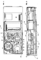
- the frame 28 has a front panel 30 connected to the forward transverse end thereof.
- the front panel has a slot or bezel closed by hinged dust door 31. This slot is sized for receiving therethrough a leader block tape cartridge (not illustrated).
- the cartridge is slid horizontally into a carriage 32 which thereafter swings downwardly via linkage 34 to engage the serrated supply reel hub (not illustrated) of the cartridge with a toothed drive chuck 36.
- the drive chuck is secured to the upper end of a vertical shaft of a first brushless DC motor 38 which is mounted to the frame 28 beneath the carriage 32.
- a horizontal deck plate 40 is mounted to the frame 28 intermediate the length of the tape transport.
- An arcuate shaped wall 42 extends vertically upward from the periphery of the deck plate.
- a threader arm (not illustrated) has its inner end rigidly coupled to the upper end of a vertical drive shaft 44 which is rotated by motor (not illustrated) mounted to the tape transport frame.
- the threader arm has a threader pin for engaging the leader block of the tape cartridge and threading the same along a tape path in the manner set forth in the aforementioned U.S. Patent No. 4,949,914, the entire disclosure of which is specifically incorporated herein by reference.
- This tape path is illustrated in Fig. 1 by an arc labeled P.
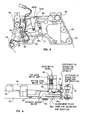
- An eighteen gap read/write head or transducer 46 (Fig. 3) is mounted above a support plate 48 between a pair of tape guide rollers 50 and 52.
- the support plate is mounted to the deck plate 40 via screws 53 (Fig. 4) to position the read/write head 46 along the tape path between the cartridge and a take-up hub (not illustrated in Figs. 1 and 2).
- the take-up hub (not illustrated) is mounted to the upper end of a vertical shaft of a second brushless DC motor 54 which is mounted to the frame.
- the take-up hub has a receptacle for receiving the leader block.
- a third tape guide roller 56 (Fig. 3) is positioned along the tape path P adjacent the periphery of the take-up hub.
- a fourth tape guide roller 58 is positioned adjacent the supply hub and the right rear corner of the carriage 32. This coincides with the corner of the tape cartridge where the tape leader block seats. The need for complex air bearings to float the tape over the read/write head is eliminated along with the associated pneumatics.
- the loading sequence of the tape transport of Figs. 1 and 2 is as follows.
- the outer end of the threader arm is initially located so that its threader pin is at the position marked with the S.
- the leader block cartridge is inserted into the tape drive and is received in carriage 32 so that the angled corner thereof with the leader block seated therein approaches the threader pin at location S.
- the height of the carriage is initially such that the narrower portion of the threader pin is received in the aperture in the leader block, while the enlarged portion is below the leader block.
- Continued pushing in of the cartridge results in full capture of the narrow upper portion of the threader pin into the aperture in the leader block.
- the carriage 32 is then lowered to capture an enlarged lower portion or shoulder of the threader pin into the enlarged portion of the aperture in the leader block.
- the threader arm is rotated counter-clockwise to pull the leader block, and the tape connected thereto around the tape guide rollers 58 and 52, past the read/write head 52, around the tape guide rollers 50 and 56 to the take-up hub.
- the threader arm then pulls the leader block into the receptacle in the take-up hub.
- the take-up hub can thereafter be rotated to wind the magnetic tape about the take-up hub, during which the leader block spins about the threader pin whose axis now coincides with the axis of rotation of the take-up hub.
- the currents to motors 36 and 54 are controlled as is well known in the art to maintain the proper tension on the tape during writing and reading. See for example U.S. Patent No. 4,125,881 of Eige et al. entitled “Tape Motion Control for Reel- to-Reel Drive.”
- a suitable tachometer assembly that may be used with each of the motors is disclosed in U.S. Patent No. 4,933,636 of Jeffrey S. McGee and entitled “Self-Aligning Tachometer and Method of Manufacturing Same".
- the oxide surface of the tape is held against the face of the read/write head 46 and against the guide rollers.
- First and second guide assemblies 60 and 62 (Fig. 1) are provided for engaging and guiding the leader block to insure proper insertion into the cartridge and into the take-up hub.
- These guide assemblies are the subject of U.S. Patent No. 4,852,825 of Jeffrey S. McGee and Thomas C. Kadien granted August 1, 1989 and entitled "Extraction and Insertion Mechanism for the Leader Block of a Tape Cartridge.”
- a first PC board 64 providing all of the necessary control electronics is horizontally mounted within the frame 28. It extends adjacent a bottom of the frame and extends approximately three-quarters of the length thereof.
- a second PC board 66 providing the servo-circuitry is horizontally mounted within the frame 28 and is spaced slightly above the forward portion of the first PC board.
- Third and fourth PC boards 68 and 70 providing the read/write circuitry are horizontally mounted within the frame 28 spaced slightly above the rearward portion of the first PC board. All of the circuitry required to read and write data in the IBM 3480 recording format is provided on the aforementioned PC boards. Extensive utilization is made of LSI circuits to minimize board area so that all the boards can fit within the eight inch form factor.
- a power supply 72 occupies a rear portion of the frame 28. It provides electrical power to the PC boards and the supply and take-up motors.
- the illustrated tape transport includes a support mechanism that permits independent head height adjustment and head azimuth adjustment.
- a finger portion 48a of the support plate is defined by a C-shaped void or cut 74.
- the outermost end of this finger portion is connected to the remainder of the support plate by a differential screw 76.
- This differential screw is mounted via connecters 78.
- the head 76a of the differential screw may be turned with a screw driver to deflect the outermost end of the finger portion up and down relative to the remainder of the support plate. This is done during final assembly of the tape transport in order to correctly align the eighteen gaps of the read/write head 46 relative to the half-inch width of the magnetic tape pulled over the same.
- the read/write 46 head is mounted to a C-shaped azimuth adjust block 80 (Fig. 4) having a flexure portion 80a.
- Another differential screw 82 extends through one leg 80b of the block 80. It may be turned during final assembly to minutely bend the block at the flexure portion 80a, thereby adjusting the azimuth angle of the head relative to the tape. This is very important in ensuring accurate writing and reading of data, and in ensuring interchangeability of tapes between drives.
- the support plate 48 thus serves as a convenient module for carrying the read/write head, its adjustable mounting mechanism and the tape guide rollers. It may be readily removed, serviced and replaced.
- a tape transport that is mechanically capable of performing all the loading, threading, tensioning, winding, re-winding and unloading functions required for the IBM 3480 leader block tape cartridge within the front half of the eight inch form factor. This is due in part to the elimination of the air bearing used in previous tape drives capable of reading and writing data in the IBM 3480 recording format.
- the transport leaves the remaining half of the form factor available for the power supply and the PC boards that provide the read/write circuitry.
- Our transport also owes its compactness to the use of LSI circuitry to miniaturize the control and servo circuits so that that can be provided on PC boards adjacent the bottom of the main frame.
- the entire tape transport weights approximately twenty-five pounds.
Landscapes
- Adjustment Of The Magnetic Head Position Track Following On Tapes (AREA)
- Digital Magnetic Recording (AREA)
- Recording Or Reproducing By Magnetic Means (AREA)
Applications Claiming Priority (2)
| Application Number | Priority Date | Filing Date | Title |
|---|---|---|---|
| US57791490A | 1990-09-05 | 1990-09-05 | |
| US577914 | 1995-12-21 |
Publications (1)
| Publication Number | Publication Date |
|---|---|
| EP0473879A1 true EP0473879A1 (fr) | 1992-03-11 |
Family
ID=24310663
Family Applications (1)
| Application Number | Title | Priority Date | Filing Date |
|---|---|---|---|
| EP91107508A Withdrawn EP0473879A1 (fr) | 1990-09-05 | 1991-05-08 | Lecteur de bandes avec tête d'écriture/lecture multipiste pour cartouche à bande avec bloc amorce |
Country Status (3)
| Country | Link |
|---|---|
| EP (1) | EP0473879A1 (fr) |
| JP (1) | JPH0594656A (fr) |
| CA (1) | CA2038073A1 (fr) |
Families Citing this family (3)
| Publication number | Priority date | Publication date | Assignee | Title |
|---|---|---|---|---|
| US5954129A (en) * | 1996-02-14 | 1999-09-21 | Takahashi; Kei | Flow control unit |
| JP3665975B2 (ja) * | 1996-02-16 | 2005-06-29 | 敬 高橋 | 流体規正搬送手段 |
| CN112993666B (zh) * | 2021-02-05 | 2022-09-09 | 温州市鸿杰电器有限公司 | 一种多功能开关插座 |
Citations (11)
| Publication number | Priority date | Publication date | Assignee | Title |
|---|---|---|---|---|
| US3372884A (en) * | 1966-03-11 | 1968-03-12 | Sony Corp | Automatic tape threading machine |
| US4340919A (en) * | 1979-03-20 | 1982-07-20 | Olympus Optical Co., Ltd. | Head adjustment mechanism |
| EP0129654A2 (fr) * | 1983-06-24 | 1985-01-02 | International Business Machines Corporation | Système d'entraînement de bande de traitement de données |
| US4550352A (en) * | 1981-10-27 | 1985-10-29 | Olympus Optical Company Limited | Head adjusting device |
| US4679747A (en) * | 1986-03-21 | 1987-07-14 | Laser Magnetic Storage International Company | Apparatus for loading and unloading the leader block of a tape cartridge |
| US4742407A (en) * | 1986-06-11 | 1988-05-03 | Aspen Peripherals | Tape threading device |
| GB2199440A (en) * | 1986-12-11 | 1988-07-06 | Brian Cattlin | Tape player |
| US4763211A (en) * | 1984-09-05 | 1988-08-09 | Hitachi, Ltd. | Floppy disc drive control circuit section substrate |
| US4852825A (en) * | 1988-09-14 | 1989-08-01 | Cipher Data Products, Inc. | Extraction and insertion mechanism for a leader block of a tape cartridge |
| EP0367593A2 (fr) * | 1988-11-03 | 1990-05-09 | Laser Magnetic Storage International, Inc. | Dispositif de transport pour cassette à bande à bobine unique |
| GB2236890A (en) * | 1989-10-13 | 1991-04-17 | Qualstar Corp | Streaming tape drive |
-
1991
- 1991-03-12 CA CA 2038073 patent/CA2038073A1/fr not_active Abandoned
- 1991-05-08 EP EP91107508A patent/EP0473879A1/fr not_active Withdrawn
- 1991-05-14 JP JP3109240A patent/JPH0594656A/ja active Pending
Patent Citations (11)
| Publication number | Priority date | Publication date | Assignee | Title |
|---|---|---|---|---|
| US3372884A (en) * | 1966-03-11 | 1968-03-12 | Sony Corp | Automatic tape threading machine |
| US4340919A (en) * | 1979-03-20 | 1982-07-20 | Olympus Optical Co., Ltd. | Head adjustment mechanism |
| US4550352A (en) * | 1981-10-27 | 1985-10-29 | Olympus Optical Company Limited | Head adjusting device |
| EP0129654A2 (fr) * | 1983-06-24 | 1985-01-02 | International Business Machines Corporation | Système d'entraînement de bande de traitement de données |
| US4763211A (en) * | 1984-09-05 | 1988-08-09 | Hitachi, Ltd. | Floppy disc drive control circuit section substrate |
| US4679747A (en) * | 1986-03-21 | 1987-07-14 | Laser Magnetic Storage International Company | Apparatus for loading and unloading the leader block of a tape cartridge |
| US4742407A (en) * | 1986-06-11 | 1988-05-03 | Aspen Peripherals | Tape threading device |
| GB2199440A (en) * | 1986-12-11 | 1988-07-06 | Brian Cattlin | Tape player |
| US4852825A (en) * | 1988-09-14 | 1989-08-01 | Cipher Data Products, Inc. | Extraction and insertion mechanism for a leader block of a tape cartridge |
| EP0367593A2 (fr) * | 1988-11-03 | 1990-05-09 | Laser Magnetic Storage International, Inc. | Dispositif de transport pour cassette à bande à bobine unique |
| GB2236890A (en) * | 1989-10-13 | 1991-04-17 | Qualstar Corp | Streaming tape drive |
Also Published As
| Publication number | Publication date |
|---|---|
| JPH0594656A (ja) | 1993-04-16 |
| CA2038073A1 (fr) | 1992-03-06 |
Similar Documents
| Publication | Publication Date | Title |
|---|---|---|
| US6469867B2 (en) | Floating tape head having side wings for longitudinal and azimuth play back with minimized tape wrap angle | |
| US6331920B1 (en) | Backward compatible head and head positioning assembly for a linear digital tape drive | |
| US5210664A (en) | Low profile tape drive for driving a mini-data cartridge | |
| US5148339A (en) | Magnetic disk storage | |
| EP0716769B1 (fr) | Unite de bande magnetique a balayage de lecture-ecriture en forme d'arc | |
| US4852825A (en) | Extraction and insertion mechanism for a leader block of a tape cartridge | |
| US4514775A (en) | Streaming cassette tape transport | |
| EP0473879A1 (fr) | Lecteur de bandes avec tête d'écriture/lecture multipiste pour cartouche à bande avec bloc amorce | |
| JPH06503671A (ja) | ヘリカル走査駆動機構用カートリッジテープ装置 | |
| US20040008445A1 (en) | One and three quarters inch form factor tape cartridge autoloader | |
| US4609958A (en) | Precision bearing for reciprocating a magnetic head | |
| US4949914A (en) | Tape transport with rigid arm threader mechanism for leader block tape cartridge | |
| US5335124A (en) | Disk drive | |
| US5592351A (en) | Low profile enclosure and mechanism for a single channel head 8mm tape drive | |
| US20010007518A1 (en) | Compact tape drive for reading and writing data on single reel magnetic tape cartridges | |
| EP0708964B1 (fr) | Mecanisme d'entrainement a balayage helicoidal pour cartouche de bande a bobine unique | |
| US5841606A (en) | Magnetic recording/reproducing device with magnetic shield between voice coil motor and flexible cable | |
| US5737147A (en) | Tape transport system utilizing a compliant frictional drive roller | |
| JP2001331991A (ja) | 媒体操作装置およびその方法 | |
| US6275359B1 (en) | Head arrangement for multitrack recording integrated tape guidance | |
| JPH04305856A (ja) | カセット判別装置とカセット、及びこれを用いたオーディオ・ビデオ機器 | |
| JP3458967B2 (ja) | 磁気記録再生装置 | |
| EP0602571A2 (fr) | Appareil d'enregistrement et/ou de reproduction magnétique | |
| EP0794504A2 (fr) | Méthode et appareil de contrÔle de transport de carte | |
| JPH0330201B2 (fr) |
Legal Events
| Date | Code | Title | Description |
|---|---|---|---|
| PUAI | Public reference made under article 153(3) epc to a published international application that has entered the european phase |
Free format text: ORIGINAL CODE: 0009012 |
|
| AK | Designated contracting states |
Kind code of ref document: A1 Designated state(s): DE FR GB IT SE |
|
| STAA | Information on the status of an ep patent application or granted ep patent |
Free format text: STATUS: THE APPLICATION IS DEEMED TO BE WITHDRAWN |
|
| 18D | Application deemed to be withdrawn |
Effective date: 19920912 |