EP0473959A2 - Verfahren zur Transformation eines Mehrstrahl-Sonarbildes - Google Patents
Verfahren zur Transformation eines Mehrstrahl-Sonarbildes Download PDFInfo
- Publication number
- EP0473959A2 EP0473959A2 EP91113298A EP91113298A EP0473959A2 EP 0473959 A2 EP0473959 A2 EP 0473959A2 EP 91113298 A EP91113298 A EP 91113298A EP 91113298 A EP91113298 A EP 91113298A EP 0473959 A2 EP0473959 A2 EP 0473959A2
- Authority
- EP
- European Patent Office
- Prior art keywords
- array
- training
- matrix
- value
- creating
- Prior art date
- Legal status (The legal status is an assumption and is not a legal conclusion. Google has not performed a legal analysis and makes no representation as to the accuracy of the status listed.)
- Granted
Links
- 238000000034 method Methods 0.000 title claims abstract description 32
- 230000001131 transforming effect Effects 0.000 title abstract description 3
- 239000011159 matrix material Substances 0.000 claims abstract description 34
- 230000000694 effects Effects 0.000 claims abstract description 7
- 238000003384 imaging method Methods 0.000 claims description 20
- 238000005070 sampling Methods 0.000 claims 4
- 230000009466 transformation Effects 0.000 description 30
- 239000002131 composite material Substances 0.000 description 17
- 230000001934 delay Effects 0.000 description 13
- 238000002604 ultrasonography Methods 0.000 description 11
- 238000000926 separation method Methods 0.000 description 10
- 238000012549 training Methods 0.000 description 10
- 238000010586 diagram Methods 0.000 description 6
- 238000004088 simulation Methods 0.000 description 6
- 238000012285 ultrasound imaging Methods 0.000 description 6
- 238000013459 approach Methods 0.000 description 5
- 230000005540 biological transmission Effects 0.000 description 5
- 239000004020 conductor Substances 0.000 description 5
- 238000012545 processing Methods 0.000 description 5
- 238000012360 testing method Methods 0.000 description 5
- 238000011426 transformation method Methods 0.000 description 5
- 238000001514 detection method Methods 0.000 description 4
- 238000009826 distribution Methods 0.000 description 4
- 238000013461 design Methods 0.000 description 3
- 230000006872 improvement Effects 0.000 description 3
- 230000008569 process Effects 0.000 description 3
- 239000000243 solution Substances 0.000 description 3
- 230000004075 alteration Effects 0.000 description 2
- 230000003111 delayed effect Effects 0.000 description 2
- 238000003745 diagnosis Methods 0.000 description 2
- 238000002592 echocardiography Methods 0.000 description 2
- 238000002474 experimental method Methods 0.000 description 2
- 238000005457 optimization Methods 0.000 description 2
- 230000004044 response Effects 0.000 description 2
- 210000001835 viscera Anatomy 0.000 description 2
- 206010028980 Neoplasm Diseases 0.000 description 1
- 238000003491 array Methods 0.000 description 1
- 210000001367 artery Anatomy 0.000 description 1
- 239000008280 blood Substances 0.000 description 1
- 210000004369 blood Anatomy 0.000 description 1
- 238000003759 clinical diagnosis Methods 0.000 description 1
- 238000011161 development Methods 0.000 description 1
- 238000002059 diagnostic imaging Methods 0.000 description 1
- 208000019622 heart disease Diseases 0.000 description 1
- 230000002452 interceptive effect Effects 0.000 description 1
- 238000012986 modification Methods 0.000 description 1
- 230000004048 modification Effects 0.000 description 1
- 230000009467 reduction Effects 0.000 description 1
- 238000002310 reflectometry Methods 0.000 description 1
- 239000012086 standard solution Substances 0.000 description 1
- 230000001629 suppression Effects 0.000 description 1
- 238000001356 surgical procedure Methods 0.000 description 1
- 238000010408 sweeping Methods 0.000 description 1
- 238000000844 transformation Methods 0.000 description 1
Images


Classifications
-
- G—PHYSICS
- G01—MEASURING; TESTING
- G01S—RADIO DIRECTION-FINDING; RADIO NAVIGATION; DETERMINING DISTANCE OR VELOCITY BY USE OF RADIO WAVES; LOCATING OR PRESENCE-DETECTING BY USE OF THE REFLECTION OR RERADIATION OF RADIO WAVES; ANALOGOUS ARRANGEMENTS USING OTHER WAVES
- G01S7/00—Details of systems according to groups G01S13/00, G01S15/00, G01S17/00
- G01S7/52—Details of systems according to groups G01S13/00, G01S15/00, G01S17/00 of systems according to group G01S15/00
- G01S7/52017—Details of systems according to groups G01S13/00, G01S15/00, G01S17/00 of systems according to group G01S15/00 particularly adapted to short-range imaging
- G01S7/52085—Details related to the ultrasound signal acquisition, e.g. scan sequences
- G01S7/5209—Details related to the ultrasound signal acquisition, e.g. scan sequences using multibeam transmission
-
- G—PHYSICS
- G01—MEASURING; TESTING
- G01S—RADIO DIRECTION-FINDING; RADIO NAVIGATION; DETERMINING DISTANCE OR VELOCITY BY USE OF RADIO WAVES; LOCATING OR PRESENCE-DETECTING BY USE OF THE REFLECTION OR RERADIATION OF RADIO WAVES; ANALOGOUS ARRANGEMENTS USING OTHER WAVES
- G01S15/00—Systems using the reflection or reradiation of acoustic waves, e.g. sonar systems
- G01S15/88—Sonar systems specially adapted for specific applications
- G01S15/89—Sonar systems specially adapted for specific applications for mapping or imaging
- G01S15/8906—Short-range imaging systems; Acoustic microscope systems using pulse-echo techniques
- G01S15/8977—Short-range imaging systems; Acoustic microscope systems using pulse-echo techniques using special techniques for image reconstruction, e.g. FFT, geometrical transformations, spatial deconvolution, time deconvolution
-
- G—PHYSICS
- G10—MUSICAL INSTRUMENTS; ACOUSTICS
- G10K—SOUND-PRODUCING DEVICES; METHODS OR DEVICES FOR PROTECTING AGAINST, OR FOR DAMPING, NOISE OR OTHER ACOUSTIC WAVES IN GENERAL; ACOUSTICS NOT OTHERWISE PROVIDED FOR
- G10K11/00—Methods or devices for transmitting, conducting or directing sound in general; Methods or devices for protecting against, or for damping, noise or other acoustic waves in general
- G10K11/18—Methods or devices for transmitting, conducting or directing sound
- G10K11/26—Sound-focusing or directing, e.g. scanning
- G10K11/34—Sound-focusing or directing, e.g. scanning using electrical steering of transducer arrays, e.g. beam steering
- G10K11/341—Circuits therefor
- G10K11/346—Circuits therefor using phase variation
Definitions
- the present invention relates to sonar imaging, such as ultrasound imaging, and more particularly to such imaging which scans an object with multiple sonar beams which are simultaneously transmitted.
- ultrasound imaging allows the examination of internal organs with far less risk than conventional surgical techniques or X-rays.
- Ultrasound imaging is used in measuring the performance of the heart, the flow of blood, to identify tumors, and in prenatal care and diagnosis.
- FIG. 1 A simplified block diagram of a typical prior art ultrasound imaging system is indicated generally at 10 in Fig. 1.
- a piezoelectric transducer array 12 comprising a stationary array of many small transducers, is stimulated by a high frequency transmitter circuit 14. When array 12 is so stimulated, it generates an ultrasonic pulse in a relatively narrow beam 16, such being illustrated schematically.
- transducer array 12 is substantially flush against and aimed into an object 18 which, in the case of medical ultrasound imaging, comprises a human body.
- the reflections of the pulse from body 18 are detected by array 12 with such signals being processed by a receiver 20 for display on a cathode ray tube 22.
- a two-dimensional image can be obtained by sweeping a beam, like beam 16, through a sector.
- a beam like beam 16
- stationary array 12 is electronically controlled to steer and focus such a beam.
- Such an array is illustrated in R.D. Gatzke, J.T. Fearnside, and S. M. Karp, "Electronic Scanner for a Phased-Array Ultrasound Transducer," Hewlett-Packard Journal, pp. 13-20, Dec. 1983, which is incorporated herein by reference.
- a pulse is transmitted in a narrow beam with the focus optimized for one line.
- the pulse is traced as it travels through the body. This process is repeated for each line until a complete image, 100-200 lines, is acquired.
- the transmission rate is selected so that echos of the transmitted pulse have time to return from the deepest target before the next pulse is transmitted.
- a recent development of great interest is three-dimensional (3-D) acoustical imaging, where a stacked set of 2-D scans yields a 3-D image of an internal organ.
- a three-dimensional array is described in H.A. McCann et al., "Multidimensional Ultrasonic Imaging for Cardiology," Proc. of the IEEE, Vol. 76, No. 9, Sept. 1988, which is incorporated herein by reference.
- such a technique could allow a non-invasive view of the heart arteries for the efficient diagnosis of heart diseases.
- current techniques and acquisition rates make impossible the implementation of a 3-D imaging system operating in real time.
- Fig. 2 indicated generally at 24 is a two-beam ultrasound system for creating an image in a single plane. Included therein are a total of K transducer elements, three of which are labeled elements 1, 2, K. Each element is associated with two time delays, d11 through d K2 , where transducer element 1 is connected to delays d11, d12; transducer element 2 is connected to delays d21, d22; and transducer element K is connected to delays d K1 , d K2 .
- a commercially available pulse generator 26 is connected to each of the delays via conductor 28.
- pulse generator 26 produces a pulse on conductor 28 it is applied to each of the delays. After a predetermined time delay, the pulse is applied to the transducer to which each delay is connected.
- the transducer elements generate an ultrasonic pulse which propagates into an object against which the transducer array is held.
- the length of the delay imposed on a pulse applied thereto for each of time delays d11 through d K2 is variable and is controlled by a computer in a known manner. Through such computer control, a preselected number of ultrasonic beams are caused to propagate from the center of the array with each beam having a preselected angle thereto. Appropriate choices of the delay settings are used to select both the angle and focus length of a transmitted beam.
- Reception of beam reflections operates in a reverse manner.
- the element When a sonar reflection strikes one of transducer elements 1-K, the element generates an electrical signal proportional to the sonar reflection which is applied to the time delays. This delays each signal by a preselected value in the same fashion as the transmitted pulse is delayed.
- Each of the delayed received signals is applied to a conductor, like the signal from delay d11 is applied to conductor 30 and the signal from delay d12 is applied to conductor 32.
- the signals from one of the delays associated with each transducer element are summed by a conventional summing device 34 with the signals from the other time delay associated with each transducer element being summed at a separate summing device 36.
- Selection of the reception angle and focus is accomplished in the same manner as selection of transmission angle and focus, i.e., by setting different time delays in a known manner.
- the array is thus caused to focus along each transmission axis at progressively increasing distances thereby sensing the sonar reflections generated by each transmitted pulse.
- System 24 comprises a 2-beam system, i.e., two ultrasonic pulses are simultaneously transmitted into the object.
- the time delays associated with summing device 34 are used to control the angle and focusing of one of the beams in the reception mode while the delays connected to summing device 36 are used to so control the other beam.
- This approach is a direct extension of the single-beam system described in R.D. Gatzke, J.T. Fearnside, and S.M. Karp, "Electronic Scanner for a Phased-Array Ultrasound Transducer," Hewlett-Packard Journal, pp. 13-20, Dec. 1983, and in its general form requires K x M delay elements for a system having M beams and K transducer elements.
- the received echo from beam j is given by where ⁇ denotes the target reflectivity.
- T m (t) denotes the composite signal that illuminates the target in the multi-beam mode
- the received signal at the output of the receiver for the j-th beam is given by From (2.1)-(2.6) it can be shown that:
- the second term in (2.7) implies that the signal received from an image target through some beam j will be affected by the transmitted energy of all other beams.
- This term is referred to herein as interbeam interference and is mainly due to the sidelobe energy of each beam.
- the interference occurs in two dimensions, namely along each arc which crosses the beams and along the axis of each beam. In a real imaging system, this interference is seen as a "butterfly pattern" around the true target.
- the present invention provides a method for imaging an object using an array of sonar transmitters.
- the array simultaneously transmits a plurality of sonar beams into an object along a plurality of lines and across a plurality of arcs.
- the sonar signal reflected along each of said lines is sensed and an image array comprised of said reflected signals is created.
- Each value in the array represents a signal reflected from one of said arcs.
- a transformed image value is created which is a function of values in the signals reflected along the simultaneously transmitted beams on both sides of the arc containing the selected element.
- the foregoing is accomplished for each element in the image array thereby creating an array of transformed image values which minimizes the effect of interbeam interference.
- Fig. 1 is a schematic diagram of a prior art single-beam ultrasonic imaging system.
- Fig. 2 is a schematic diagram of a multi-beam, sonar imaging system utilized in implementing the present invention.
- Fig. 3 is a schematic diagram of a K element ultrasound transducer array.
- Fig. 4A is a diagram of the position of a number of values sampled in a single-beam ultrasound image field.
- Fig. 4B is a diagram of the position of a number of values sampled in a multi-beam ultrasound image field in accordance with the present invention.
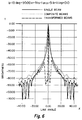
- Fig. 5 is a plot of brightness versus line angle for an ultrasound 5-beam scan transformed in accordance with the present invention and being superimposed over the untransformed scan and a single-beam scan.
- Fig. 6 is a plot similar to Fig. 5 using a 10-beam scan.
- the transducer in the Fig. 2 system sends several beams simultaneously into the image field. These simultaneously transmitted beams are referred to as the beam array .
- M 2.
- the focusing distances are the same for all beams in the array and the beams are separated by ⁇ lines or ⁇ deg degrees.
- the beam separation and the line (or angular) resolution of a multi-beam system are independent quantities. For example, one can have a beam array with a 5 degree beam separation but rotate it only 0.5 degrees at a time thus achieving a 0.5 degree line resolution.
- each position of the beam array is characterized by a pair of numbers (j,p) where j is the receive focusing arc number and p is the line position of the array.
- j the receive focusing arc number
- p the line position of the array.
- the beam array scans the image field as follows. Assume that at the beginning the beam array is in position (0,0) and the separation between beams is ⁇ . Transmit on all beams and receive the reflections from all arcs. Move the array one line to the right and transmit again. Continue until the line number of beam 0 is the same as the initial line number of beam 1. (This means that beam 0 is about to scan a line that has already been scanned.) Then jump to a new position such that the line position of beam 0 will be just to the right of the last line position of the beam M -1, and continue as described above. We will refer to this scanning format as the scan and jump format.
- each pulse transmitted along a line reflects a signal which contains information about the media through which the signal passes.
- the reflected signal is periodically sampled to produce a plurality of sampled values for each such signal.
- Each value can be keyed to a location in the image field, as illustrated in Fig. 4B.
- the sampled values illustrated in Fig. 4B are referred to herein as an image array or matrix with each sampled value, x(j,i) comprising an element in the matrix.
- the transformation just described can be performed either in the RF domain or in the video domain (i.e., after detection).
- the image matrix so transformed is referred to herein as a matrix of transformed image values. Transformation after detection is easier to implement and that is why this transformation mode was chosen to implement the present embodiment of the invention.
- the transformation method and the procedure for finding the optimum transformation coefficients is described now in a more detailed fashion.
- the present invention is preferably implemented with more than two beams.
- the 2-beam system of Fig. 2 is used to simplify the description of the preferred embodiment.
- the beam configuration can be arbitrary.
- the transformation method of the present invention can be applied regardless of beam array orientation.
- the brightness distribution over the image field can be described by a two-dimensional quantity x(j,i) which represents the received value (after detection) from the point (j,i) .
- x(j,i) represents the received value (after detection) from the point (j,i) .
- different points are imaged by different beams.
- x(m,j,p) which is the value (after detection) received through the beam m from the arc j when the beam array is in the position p along that arc.
- the value x(m,j,p) is called a composite value since it represents a combination of reflected values from pulses transmitted through all the beams.
- a composite set includes the M signals received by the beams in a given angular position of the beam array rather than the signals corresponding to M consecutive points of the arc (they will be the same only if the beam separation is equal to one line).
- the set is constructed that way because a received signal will be affected only by the signals transmitted by other beams at the same time i.e., in the same position of the beam array, rather than by the signals corresponding to the adjacent points on the arc.
- the three-dimensional array ⁇ c(m,l,b) ⁇ is the array of transformation coefficients.
- This array of transformation coefficients is referred to as the transformation kernel of width M depth L and height M .
- the transformation coefficients are the key component of the transformation equation (3.1). They can be determined to minimize interbeam interference. Mathematically, this condition can be stated as follows. Let d(m,j,p) be the desired value of y(m,j,p), i.e. the value without the interbeam interference. Then the c coefficients can be found by minimizing the RMS error between the transformed and the desired signals, over the entire image field, i.e.: Note that the minimization is done independently for each m .
- the matrix of sampled image values collected from a scan of the training-object is referred to herein as a matrix of training-object sampled values.
- the desired signal for each beam m scanning such a training-object is a delta function equal to one when the beam looks right at the target and zero elsewhere.
- Other desired signals might also be used, such as an actual signal from a single-beam scan of the training-object. Such a desired signal is referred to herein as an ideal training-object matrix.
- the optimizing equation (3.2) can be thought of as a "training equation” because it tells us how we can train the system with the training picture and the corresponding desired response to produce an optimum set of the transformation coefficients.
- this equation it was assumed that the composite and the desired signals had been obtained using the "scan and jump" scanning format described above. However, if the desired function is a delta function that scanning format will not produce a meaningful set of transformation coefficients. In the "scan and jump" approach only one beam will ever see the test target. Hence, the desired functions for all other beams in the array will be identically zero. Then the solution to the RMS problem will be satisfied by a set of transformation coefficients that are all zero and of no practical use.
- the objects can have arbitrary angular orientations with respect to each beam in the array. So, to produce a robust set of the transformation coefficients we would like to have a training procedure that includes as many different orientations of a test target with respect to each beam in the array as possible.
- the "scan and jump" scanning algorithm does allow each beam to visit all the arcs in the image field, however, only a limited number of lines can be visited.
- the scan algorithm is modified so that the beam array always rotates only one line at a time in the training mode. That is, for a given angular position of the beam array we scan all the arcs from 0 to J -1 and then move the array one line to the right so that beam 0 now faces the same direction as beam 1 in the previous angular position, beam 1 faces the same position as beam 2, etc.
- this scanning mode as the training mode as opposite to the imaging mode which uses the "scan and jump" format.
- the composite, transformed and desired signals for the training mode are denoted as x T (m,j,p),y T (m,j,p) and d T (m,j,p) , respectively.
- the same quantities without the subscript T refers to the imaging mode.
- the optimization equation (3.2) is rewritten now in the following form:
- Equation (3.3) is actually M independent equations.
- c(m,l,b) equate the derivatives to zero and solve for the unknowns.
- the solution of (3.4) can be written in a closed form if we introduce a matrix notation. In this notation lower case letters denote matrix elements and upper case letters denote the corresponding matrices.
- a time domain simulator of the multi-beam ultrasonic imaging system was developed.
- the simulator produces images for arbitrary target distributions for single-beam, multi-beam, and multi-beam transformed systems, allowing for a wide range of experimentation in the main system parameters such as number of beams, beam separation, size and resolution of the imaging field, number of phased array elements, etc.
- the target distribution used in the simulations comprises a single target of unit brightness, located at the center of the imaging field, on the line at 0 degrees and the arc at 100 mm.
- Figs. 5 and 6 each show beam plot simulations of the above-described training-object (a point target) with the vertical axis comprising the maximum brightness (in dB) along each line plotted against the angle of the line relative to the transducer array.
- Each plot shows the simulated images produced by a single-beam system, a 5-beam system without transformation (referred to as a composite system) and a 5-beam system with transformation.
- An ideal response in both Figs. 5 and 6 would comprise a plot with no signal at all angles except zero degrees at which angle a single impulse of zero dB would appear.
- the plot of the beams transformed in accordance with the present invention provides the most accurate result.
- Figs. 5 and 6 assume no phase aberrations.
- a human body which includes various types of tissue, each of which transmits sonar pulses at different velocities, the received signals are slightly shifted relative to one another due to the difference in pulse travel time from signal to signal.
- random phase aberrations are included as part of the simulated system, the quality of the 5-beam transformed image appears to be slightly superior to that of the 10-beam transformed image and both at some line angles are inferior to the single-beam images. This indicates an expected trade-off between image quality and data acquisition rate.
- the beam plots of Figs. 5 and 6 also indicate that while beam transformation is very good at removing interference and improving resolution close to targets, it also produces sharp side lobes at moderate distance from the targets.
- This ringing effect is due in part to the use of an ideal delta function as the desired signal in the optimization procedure for transformation coefficients. An improvement in the ringing effect can be expected if a smoother function is used as the desired signal.
- a natural candidate for the desired signal is a signal resembling the one produced by a single-beam system.
Landscapes
- Engineering & Computer Science (AREA)
- Physics & Mathematics (AREA)
- Radar, Positioning & Navigation (AREA)
- Remote Sensing (AREA)
- Acoustics & Sound (AREA)
- Computer Networks & Wireless Communication (AREA)
- General Physics & Mathematics (AREA)
- Multimedia (AREA)
- Measurement Of Velocity Or Position Using Acoustic Or Ultrasonic Waves (AREA)
- Ultra Sonic Daignosis Equipment (AREA)
- Transducers For Ultrasonic Waves (AREA)
Applications Claiming Priority (2)
| Application Number | Priority Date | Filing Date | Title |
|---|---|---|---|
| US568455 | 1990-08-15 | ||
| US07/568,455 US5105814A (en) | 1990-08-15 | 1990-08-15 | Method of transforming a multi-beam ultrasonic image |
Publications (3)
| Publication Number | Publication Date |
|---|---|
| EP0473959A2 true EP0473959A2 (de) | 1992-03-11 |
| EP0473959A3 EP0473959A3 (en) | 1992-10-28 |
| EP0473959B1 EP0473959B1 (de) | 1996-06-05 |
Family
ID=24271369
Family Applications (1)
| Application Number | Title | Priority Date | Filing Date |
|---|---|---|---|
| EP91113298A Expired - Lifetime EP0473959B1 (de) | 1990-08-15 | 1991-08-08 | Verfahren zur Transformation eines Mehrstrahl-Sonarbildes |
Country Status (4)
| Country | Link |
|---|---|
| US (1) | US5105814A (de) |
| EP (1) | EP0473959B1 (de) |
| JP (1) | JPH04244145A (de) |
| DE (1) | DE69120004T2 (de) |
Cited By (8)
| Publication number | Priority date | Publication date | Assignee | Title |
|---|---|---|---|---|
| DE4304275A1 (de) * | 1992-04-17 | 1994-01-13 | Hewlett Packard Co | Verfahren und Vorrichtung zum Erhöhen der Bildwechselfrequenz und der Auflösung eines Phased-Array-Bildsystemes |
| WO1994011757A1 (en) * | 1992-11-12 | 1994-05-26 | Massachusetts Institute Of Technology | High resolution phased array echo imager |
| EP0678003A4 (de) * | 1992-12-21 | 1995-12-06 | ||
| US5623928A (en) * | 1994-08-05 | 1997-04-29 | Acuson Corporation | Method and apparatus for coherent image formation |
| DE4345221C2 (de) * | 1992-04-17 | 1998-04-30 | Hewlett Packard Co | Verfahren und Vorrichtung zum Erhöhen der Auflösung eines Phased-Array-Bildsystemes |
| US5793701A (en) * | 1995-04-07 | 1998-08-11 | Acuson Corporation | Method and apparatus for coherent image formation |
| US5921932A (en) * | 1994-08-05 | 1999-07-13 | Acuson Corporation | Method and apparatus for a baseband processor of a receive beamformer system |
| US6029116A (en) * | 1994-08-05 | 2000-02-22 | Acuson Corporation | Method and apparatus for a baseband processor of a receive beamformer system |
Families Citing this family (31)
| Publication number | Priority date | Publication date | Assignee | Title |
|---|---|---|---|---|
| US5383457A (en) * | 1987-04-20 | 1995-01-24 | National Fertility Institute | Method and apparatus for processing images |
| JPH05277127A (ja) * | 1992-04-02 | 1993-10-26 | Toshiba Corp | 結石破砕装置 |
| US5301168A (en) * | 1993-01-19 | 1994-04-05 | Hewlett-Packard Company | Ultrasonic transducer system |
| US5349262A (en) * | 1994-02-22 | 1994-09-20 | Hewlett-Packard Company | Phased array ultrasound imaging system with dynamic elevation focusing |
| US5540230A (en) * | 1994-04-15 | 1996-07-30 | Echocath, Inc. | Diffracting doppler-transducer |
| US5462057A (en) * | 1994-06-06 | 1995-10-31 | Hewlett-Packard Company | Ultrasound imaging system using line splicing and parallel receive beam formation |
| US5515852A (en) * | 1994-06-06 | 1996-05-14 | Hewlett-Packard Company | Method and apparatus for a detection strength spatial filter in an ultrasound imaging system |
| US5685308A (en) * | 1994-08-05 | 1997-11-11 | Acuson Corporation | Method and apparatus for receive beamformer system |
| US5675554A (en) * | 1994-08-05 | 1997-10-07 | Acuson Corporation | Method and apparatus for transmit beamformer |
| DE19581718T5 (de) * | 1994-08-05 | 2013-11-07 | Siemens Medical Solutions USA, Inc. (n.d. Ges. d. Staates Delaware) | Verfahren und Vorrichtung für Sendestrahlformersystem |
| US5608690A (en) * | 1995-03-02 | 1997-03-04 | Acuson Corporation | Transmit beamformer with frequency dependent focus |
| US6005827A (en) | 1995-03-02 | 1999-12-21 | Acuson Corporation | Ultrasonic harmonic imaging system and method |
| US6027448A (en) * | 1995-03-02 | 2000-02-22 | Acuson Corporation | Ultrasonic transducer and method for harmonic imaging |
| US5678554A (en) * | 1996-07-02 | 1997-10-21 | Acuson Corporation | Ultrasound transducer for multiple focusing and method for manufacture thereof |
| US5891037A (en) * | 1997-12-18 | 1999-04-06 | Acuson Corporation | Ultrasonic Doppler imaging system with frequency dependent focus |
| WO1999056626A1 (en) * | 1998-05-05 | 1999-11-11 | Cornell Research Foundation, Inc. | Method for assessing blood flow and apparatus thereof |
| US6179780B1 (en) * | 1999-08-06 | 2001-01-30 | Acuson Corporation | Method and apparatus for medical diagnostic ultrasound real-time 3-D transmitting and imaging |
| US6447452B1 (en) * | 2000-06-29 | 2002-09-10 | Siemens Medical Solutions Usa, Inc. | System and method for reduction of parallel beamforming artifacts |
| ES2402270T3 (es) * | 2002-10-10 | 2013-04-30 | Visualsonics Inc. | Sistema de formación de imágenes por ultrasonidos de alta frecuencia y de alta frecuencia de fotogramas |
| US9244160B2 (en) | 2003-01-14 | 2016-01-26 | University Of Virginia Patent Foundation | Ultrasonic transducer drive |
| WO2004064619A2 (en) * | 2003-01-14 | 2004-08-05 | University Of Virginia Patent Foundation | Ultrasound imaging beam-former apparatus and method |
| JP4244300B2 (ja) * | 2003-03-24 | 2009-03-25 | 富士フイルム株式会社 | 超音波送受信装置 |
| JP2004286680A (ja) * | 2003-03-24 | 2004-10-14 | Fuji Photo Film Co Ltd | 超音波送受信装置 |
| KR100967951B1 (ko) * | 2003-06-02 | 2010-07-06 | 트랜스퍼시픽 소닉, 엘엘씨 | 비동기 전송모드를 이용하는 cdma 시스템에서의 음성통화를 위한 aal0 구조 |
| JP2007525299A (ja) * | 2004-03-01 | 2007-09-06 | サニーブルック アンド ウィメンズ カレッジ ヘルス サイエンシーズ センター | Ecgトリガレトロスペクティブカラーフロー超音波イメージングのためのシステムおよび方法 |
| US9232920B2 (en) * | 2004-03-19 | 2016-01-12 | General Electric Company | Self-expanding multi-channel RF receiver coil for high resolution intra-cardiac MRI and method of use |
| JP4494089B2 (ja) * | 2004-06-02 | 2010-06-30 | 富士フイルム株式会社 | 超音波送受信装置 |
| KR101590253B1 (ko) * | 2014-06-23 | 2016-02-01 | 포항공과대학교 산학협력단 | 이미징 소나의 이미지 예측 시뮬레이션 방법 및 이를 이용한 장치 |
| US10627507B1 (en) * | 2017-06-15 | 2020-04-21 | Northrop Grumman Systems Corporation | Multibeam transmitter system and method |
| US11918300B2 (en) * | 2018-01-23 | 2024-03-05 | Koninklijke Philips N.V. | Ultrasound imaging system providing needle insertion guidance |
| CN108784737B (zh) * | 2018-05-31 | 2021-06-01 | 东软医疗系统股份有限公司 | 一种超声成像的波束合成方法和装置 |
Family Cites Families (8)
| Publication number | Priority date | Publication date | Assignee | Title |
|---|---|---|---|---|
| FR2478822A1 (fr) * | 1980-03-18 | 1981-09-25 | Thomson Csf | Systeme de detection active au moyen d'emissions multiples simultanees |
| FR2514910A1 (fr) * | 1981-10-19 | 1983-04-22 | Labo Electronique Physique | Dispositif de traitement des echos dans un appareil d'exploration de milieux par echographie ultrasonore et appareil d'exploration de milieux comprenant un tel dispositif de traitement |
| JPH06100647B2 (ja) * | 1983-10-19 | 1994-12-12 | 日本電気株式会社 | コヒアレントサイドロ−ブキャンセラ |
| KR940009243B1 (ko) * | 1985-08-07 | 1994-10-01 | 가부시기가이샤 히다찌세이사꾸쇼 | 초음파 수파 정상회로 |
| US4866614A (en) * | 1985-12-26 | 1989-09-12 | General Electric Company | Ultrasound characterization of 3-dimensional flaws |
| EP0335578A3 (de) * | 1988-03-28 | 1990-08-01 | Hewlett-Packard Company | Ultraschall-Abbildungssystem mit zwei oder mehreren gleichzeitig aktiven Aperturen |
| FR2637400B1 (fr) * | 1988-09-30 | 1990-11-09 | Labo Electronique Physique | Dispositif de traitement ameliore d'un signal echographique |
| FR2638884B1 (fr) * | 1988-11-10 | 1990-12-28 | Labo Electronique Physique | Dispositif de focalisation tridimensionnelle d'un faisceau ultrasonore |
-
1990
- 1990-08-15 US US07/568,455 patent/US5105814A/en not_active Expired - Fee Related
-
1991
- 1991-08-08 EP EP91113298A patent/EP0473959B1/de not_active Expired - Lifetime
- 1991-08-08 DE DE69120004T patent/DE69120004T2/de not_active Expired - Fee Related
- 1991-08-14 JP JP3228761A patent/JPH04244145A/ja active Pending
Cited By (13)
| Publication number | Priority date | Publication date | Assignee | Title |
|---|---|---|---|---|
| DE4345221C2 (de) * | 1992-04-17 | 1998-04-30 | Hewlett Packard Co | Verfahren und Vorrichtung zum Erhöhen der Auflösung eines Phased-Array-Bildsystemes |
| DE4304275A1 (de) * | 1992-04-17 | 1994-01-13 | Hewlett Packard Co | Verfahren und Vorrichtung zum Erhöhen der Bildwechselfrequenz und der Auflösung eines Phased-Array-Bildsystemes |
| US5678552A (en) * | 1992-04-17 | 1997-10-21 | Hewlett-Packard Company | Method and apparatus for increasing the frame rate and resolution of a phased-array imaging system |
| DE4345380C2 (de) * | 1992-04-17 | 1998-03-26 | Hewlett Packard Co Palo Alto | Verfahren und Vorrichtung zum Erhöhen der Bildwechselfrequenz eines Phased-Array-Bildsystems |
| DE4345381C2 (de) * | 1992-04-17 | 1998-04-16 | Hewlett Packard Co | Vorrichtung zum Erhöhen der Bildwiederholrate eines Phased-Array-Bildsystems |
| WO1994011757A1 (en) * | 1992-11-12 | 1994-05-26 | Massachusetts Institute Of Technology | High resolution phased array echo imager |
| EP0678003A4 (de) * | 1992-12-21 | 1995-12-06 | ||
| US5623928A (en) * | 1994-08-05 | 1997-04-29 | Acuson Corporation | Method and apparatus for coherent image formation |
| US5921932A (en) * | 1994-08-05 | 1999-07-13 | Acuson Corporation | Method and apparatus for a baseband processor of a receive beamformer system |
| US5928152A (en) * | 1994-08-05 | 1999-07-27 | Acuson Corporation | Method and apparatus for a baseband processor of a receive beamformer system |
| US6016285A (en) * | 1994-08-05 | 2000-01-18 | Acuson Corporation | Method and apparatus for coherent image formation |
| US6029116A (en) * | 1994-08-05 | 2000-02-22 | Acuson Corporation | Method and apparatus for a baseband processor of a receive beamformer system |
| US5793701A (en) * | 1995-04-07 | 1998-08-11 | Acuson Corporation | Method and apparatus for coherent image formation |
Also Published As
| Publication number | Publication date |
|---|---|
| EP0473959A3 (en) | 1992-10-28 |
| DE69120004D1 (de) | 1996-07-11 |
| JPH04244145A (ja) | 1992-09-01 |
| US5105814A (en) | 1992-04-21 |
| DE69120004T2 (de) | 1996-12-19 |
| EP0473959B1 (de) | 1996-06-05 |
Similar Documents
| Publication | Publication Date | Title |
|---|---|---|
| US5105814A (en) | Method of transforming a multi-beam ultrasonic image | |
| Nock et al. | Synthetic receive aperture imaging with phase correction for motion and for tissue inhomogeneities. I. Basic principles | |
| Von Ramm et al. | Beam steering with linear arrays | |
| Thurstone et al. | A new ultrasound imaging technique employing two-dimensional electronic beam steering | |
| US6282963B1 (en) | Numerical optimization of ultrasound beam path | |
| JP4172841B2 (ja) | 超音波イメージング・システム、超音波イメージング・システムを動作させる方法及びマルチプレクサ・マザーボード | |
| US5817023A (en) | Ultrasound imaging system with dynamic window function generator | |
| US4817434A (en) | Device for imaging three dimensions using simultaneous multiple beam formation | |
| US5951479A (en) | Method and apparatus for synthetic transmit aperture imaging | |
| Nikolov et al. | Recursive ultrasound imaging | |
| EP1004894B1 (de) | Verfahren und Vorrichtung zur Ultraschall- Bilddatenerfassung mit Erhöhung der Bildfrequenz und Bildauflösung | |
| US6063033A (en) | Ultrasound imaging with higher-order nonlinearities | |
| Ranganathan et al. | A novel beamformer design method for medical ultrasound. Part I: Theory | |
| US5415173A (en) | Ultrasound diagnosis system | |
| US20030216645A1 (en) | Two dimensional array and methods for imaging in three dimensions | |
| WO1993012444A2 (en) | Synthetic aperture ultrasound imaging system | |
| KR20010051946A (ko) | 다차원 센서 어레이를 배치한 고해상도 3차원 초음파 영상시스템 및 센서 신호를 다차원 빔형성하는 방법 | |
| US4553437A (en) | Hybrid non-invasive ultrasonic imaging system | |
| US5966169A (en) | Three dimensional beamformed television | |
| Phillips et al. | Sampled aperture techniques applied to B-mode echoencephalography | |
| US6368276B1 (en) | Deep penetration beamformed television | |
| US8038620B2 (en) | Fresnel zone imaging system and method | |
| US4688430A (en) | Device for imaging three dimensions with a single pulse transmission | |
| Drukarev et al. | Beam transformation techinques for ultrasonic medical imaging | |
| Hazard et al. | Effects of motion on a synthetic aperture beamformer for real-time 3D ultrasound |
Legal Events
| Date | Code | Title | Description |
|---|---|---|---|
| PUAI | Public reference made under article 153(3) epc to a published international application that has entered the european phase |
Free format text: ORIGINAL CODE: 0009012 |
|
| AK | Designated contracting states |
Kind code of ref document: A2 Designated state(s): DE FR GB |
|
| PUAL | Search report despatched |
Free format text: ORIGINAL CODE: 0009013 |
|
| AK | Designated contracting states |
Kind code of ref document: A3 Designated state(s): DE FR GB |
|
| 17P | Request for examination filed |
Effective date: 19930121 |
|
| 17Q | First examination report despatched |
Effective date: 19941025 |
|
| GRAH | Despatch of communication of intention to grant a patent |
Free format text: ORIGINAL CODE: EPIDOS IGRA |
|
| GRAA | (expected) grant |
Free format text: ORIGINAL CODE: 0009210 |
|
| AK | Designated contracting states |
Kind code of ref document: B1 Designated state(s): DE FR GB |
|
| REF | Corresponds to: |
Ref document number: 69120004 Country of ref document: DE Date of ref document: 19960711 |
|
| ET | Fr: translation filed | ||
| PLBE | No opposition filed within time limit |
Free format text: ORIGINAL CODE: 0009261 |
|
| STAA | Information on the status of an ep patent application or granted ep patent |
Free format text: STATUS: NO OPPOSITION FILED WITHIN TIME LIMIT |
|
| 26N | No opposition filed | ||
| PGFP | Annual fee paid to national office [announced via postgrant information from national office to epo] |
Ref country code: FR Payment date: 19970721 Year of fee payment: 7 |
|
| PGFP | Annual fee paid to national office [announced via postgrant information from national office to epo] |
Ref country code: DE Payment date: 19970722 Year of fee payment: 7 |
|
| PGFP | Annual fee paid to national office [announced via postgrant information from national office to epo] |
Ref country code: GB Payment date: 19970728 Year of fee payment: 7 |
|
| PG25 | Lapsed in a contracting state [announced via postgrant information from national office to epo] |
Ref country code: GB Free format text: LAPSE BECAUSE OF NON-PAYMENT OF DUE FEES Effective date: 19980808 |
|
| GBPC | Gb: european patent ceased through non-payment of renewal fee |
Effective date: 19980808 |
|
| PG25 | Lapsed in a contracting state [announced via postgrant information from national office to epo] |
Ref country code: FR Free format text: LAPSE BECAUSE OF NON-PAYMENT OF DUE FEES Effective date: 19990430 |
|
| PG25 | Lapsed in a contracting state [announced via postgrant information from national office to epo] |
Ref country code: DE Free format text: LAPSE BECAUSE OF NON-PAYMENT OF DUE FEES Effective date: 19990601 |
|
| REG | Reference to a national code |
Ref country code: FR Ref legal event code: ST |