EP0473982A2 - Pierre de manteau de cheminée pour cheminées domestiques - Google Patents
Pierre de manteau de cheminée pour cheminées domestiques Download PDFInfo
- Publication number
- EP0473982A2 EP0473982A2 EP91113588A EP91113588A EP0473982A2 EP 0473982 A2 EP0473982 A2 EP 0473982A2 EP 91113588 A EP91113588 A EP 91113588A EP 91113588 A EP91113588 A EP 91113588A EP 0473982 A2 EP0473982 A2 EP 0473982A2
- Authority
- EP
- European Patent Office
- Prior art keywords
- casing
- wall
- recess
- stone
- flow channel
- Prior art date
- Legal status (The legal status is an assumption and is not a legal conclusion. Google has not performed a legal analysis and makes no representation as to the accuracy of the status listed.)
- Granted
Links
Images


Classifications
-
- E—FIXED CONSTRUCTIONS
- E04—BUILDING
- E04F—FINISHING WORK ON BUILDINGS, e.g. STAIRS, FLOORS
- E04F17/00—Vertical ducts; Channels, e.g. for drainage
- E04F17/02—Vertical ducts; Channels, e.g. for drainage for carrying away waste gases, e.g. flue gases; Building elements specially designed therefor, e.g. shaped bricks or sets thereof
- E04F17/023—Vertical ducts; Channels, e.g. for drainage for carrying away waste gases, e.g. flue gases; Building elements specially designed therefor, e.g. shaped bricks or sets thereof made of masonry, concrete or other stone-like material; Insulating measures and joints therefor
Definitions
- the invention relates to a casing stone for a multi-layer house chimney according to the preamble of claim 1.
- Such casing stones for multi-layer chimneys are known (see e.g. DE-PS 3211536).
- the solution proposed here has the disadvantage that the flow channels arranged on both sides of the corner regions have a very unfavorable cross section in terms of flow technology, since they are elongated and at the same time narrow.
- the shape for the production of the casing stones is complex because of the uneven shape and the large number of flow channels.
- the invention has for its object to design a casing for multi-layer chimneys so that an optimal effect of the flow channels is achieved at minimal cost and at the same time recesses for reinforcing iron and / or potting compound can be formed.
- the actual corner area is used to support the insulation layer, as a result of which a considerable part of the cross-sectional area usable in the corner area is lost for the flow channel.
- firstly two channels must be arranged in each corner area and secondly the channels must extend very far in the direction of the central area of the casing stone. Because of the shallow cross-sectional depth towards the center, the span on which the insulation layer is interrupted increases very quickly, while the cross-sectional area increases only slightly.
- the casing stone according to the invention achieves a larger total cross-sectional area with only one flow channel in each corner area with the same span the flow channels with a more favorable cross-sectional shape and a larger contact surface for the insulation layer.
- the casing block according to the invention offers the possibility of using different shapes of recesses, the size of the recesses being chosen to be as small as is necessary for the intended use in order not to waste space for the flow channels. Usual dimensions are in the range from 25 mm to 60 mm. They are therefore somewhat smaller than the wall thickness of conventional casing stones, which is between 40 mm and 100 mm.
- the limitation of the wall thickness of the recess in the intended area has the effect that the strength properties and also the fire resistance duration of the casing stones are not adversely affected by the recess. This applies in particular if the sum of the individual wall thicknesses is greater than or equal to 100% of the wall thickness in the adjacent areas, which is achieved with a minimum of space if the wall thickness on all sides is 50% of the wall thickness in the adjacent areas. However, it can also be expedient to choose the wall thickness on the outside to be greater than 50% and correspondingly less than 50% on the side towards the flow channel. Especially if the recesses are already in the manufacturing plant, e.g. when putting together several casing stones, it may also be sufficient to form both walls with only 40% of the wall thickness in the adjacent areas, since in this case the sealing compound increases the strength of the corner area.
- the shape of the recess e.g. triangular, square or oval cross sections can be selected.
- the creation of circular recesses is particularly simple in terms of shape, it also has the advantage that reinforcement bars introduced can be fixed on all sides at the same distance from the casing stone.
- the center point of the recess is expediently arranged on the bisector of the corner of the casing stone.
- the lateral boundary area of the flow channel essentially at an angle of 80 ° to 100 ° to the adjacent wall piece, preferably perpendicular to the latter.
- the lateral boundaries were each arranged parallel to the bisector of the corner, which only partially uses the available space when the opening of the flow channel is limited in width.
- a good support of the insulation layer on the casing stone is obtained if the open opening to the insulation layer formed by the flow channel is smaller or at most the same as the adjacent area of the casing stone which supports the insulation layer. If flow ducts are only arranged in corner areas, as is preferably assumed, the supporting surface is therefore always at least 50% of the total circumferential surface. Dimensionally stable shells do not necessarily have to be used for the insulation layer, but preformed, profiled plates can also be used, which are only bent in a circular or semicircular shape at the installation site. When using two insulation boards per perimeter, the supporting area is still sufficient to hold both boards securely on a supporting surface.
- the wall thickness in the area of the rounded wall part may be somewhat larger than in the area of the flow channel in order to cover the area for the flow channel given the unfavorable geometric conditions given here to enlarge.
- a horizontal flow channel passing between the flow channels, through which air from one flow channel to the next flow channel or diffused water vapor from the center area of the Mantel stones can be transported to the flow channels.
- a similar horizontal channel can also be formed for a cladding brick, in which the wall thickness in the straight wall section and at the narrowest point of the rounded wall part is the same. Such a channel does not establish a continuous connection between two vertical flow channels. However, it can serve to guide diffused water vapor to the flow channel.
- the wall thickness of the casing stone in the area of the horizontal channel is not less than the wall thickness in the area of the straight wall piece, so that the strength behavior and the fire resistance behavior of the casing stone are not deteriorated.
- each chimney draft has four flow channels arranged in corner areas.
- these corner areas are identical to the corners of the casing.
- flow channels can also be formed in the interstices between two inner tubes or in the corner areas to form an adjoining air shaft.
- Such corner areas too can be used for the arrangement of recesses under certain circumstances.
- Such an air shaft will then have a fillet in the area of the recess which is a mirror image of the usual fillets, that is to say it is convex when viewed from the shaft.
- casing stones according to the invention large-format chimney elements can be produced in the manufacturing plant by placing several casing stones with mortar on top of one another, inserting reinforcing bars into the recesses and casting them with potting compound or screwing threaded rods at the ends of the fittings.
- Such shaped pieces can be storey-high or house-high, the stability for transport and assembly being ensured by the cast reinforcement or the threaded rods under tensile stress.
- Such casing stones can also be used to build particularly stable chimneys on site, which are able to withstand static loads, e.g. due to wind attack, to be taken up over a greater height than normal house chimneys, in which only the dead weight counteracts the wind load.
- static loads e.g. due to wind attack
- the mantles are not suitable as load-bearing components due to their limited wall thickness, which does not exceed 10 cm, even with larger cross-sectional dimensions, but for house chimneys that have wind forces above the roof in a limited height ( ⁇ 3 m) are exposed.
- All shown stones are usually made of lightweight concrete with an open or closed structure with a density of approx. 1.0 to 1.8 g / cm3.
- the height of a fitting is predominantly 33 cm, but it is also possible to manufacture higher fittings up to the floor height.
- the fittings are used for house chimneys with light widths from 12 cm to 0.8 m.
- the outer dimensions have a length of approx. 30 cm to 2 m.
- the wall thickness of the fittings is 4 cm for small light widths and increases to 10 cm for large light widths.
- the recess (6) is shown in the upper left quadrant of Fig. 1 as a square, in the upper right quadrant as a combination of a triangle and a semicircle, in the lower left quadrant as a right triangle and in the lower right quadrant as a circle.
- the recesses are arranged so that they are each symmetrical to the bisector (36) of the adjacent corner of the casing stone (2).
- the inner wall surface (10) of the recess is opposite a corresponding wall part (8) on the side of the flow channel, which runs parallel to the inner wall (10) of the recess in the two left quadrants and concentrically in the two right quadrants.
- the wall thickness from the recess (6) to the flow channel (4) is 50% of the wall thickness of the casing stone in the adjacent area (12) of the flow channels (4) which is not penetrated by a recess (6).
- the flow channels (4) are formed by the wall (8) of the recess, the two walls of the straight wall section (12), the two rope boundary surfaces (16) and the open opening to the insulation layer (curve (38) shown in broken lines).
- the minimum wall thickness of the casing stone in the area of the rounded wall part is somewhat larger than the wall thickness in the adjacent area (12) of the flow channel (4) which is not penetrated by a recess.
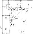
- Fig. 2 shows a quadrant of a casing stone with a circular recess on a larger scale.
- the ratios of the wall thicknesses of the casing in the different areas are represented by a general dimensioning, a preferred value for the dimension a for chimney clearances of 12 cm to 22 cm being a value of 40 mm.
- the mantle shown corresponds in size to a chimney with 16 cm light width and 36 cm outside dimension.
- the wall between the recess (6) and the flow channel (4) is formed by an annular cutout (14).
- the convexly curved wall (8) of the flow channel (4) merges with a small rounding (20) into the wall piece (12) with a uniform wall thickness.
- the transition to the adjacent lateral boundary surface (16) and to the circular boundary surface (18) of the rounded wall part (42) also takes place with a small fillet (20).
- the lateral boundary surface is essentially (apart from the fillets) perpendicular to the surface of the wall piece (12) aligned.
- the length of the lateral boundary surface is in the small casing dimensions shown relatively short. In the case of larger chimney cross-sections, it can reach a considerable size, since, due to the increasing depth of the flow channels, the width of the channel does not have to increase in the same proportion as the clear width of the chimney.
- the chimney has a small light width, it may happen that the area of the flow channel is not large enough with the same wall thicknesses in the area of the straight wall section (12) and at the narrowest point of the rounded wall section (42).
- Increasing the open passage area (40) of the flow channel to the insulation layer beyond one eighth of the circumferential surface of the casing stone does not bring about any significant improvement because of the small difference in dimensions between the rounded wall part (42) and the straight wall piece (12).
- the wall thickness in the narrow region of the rounded wall part (42) can be selected somewhat larger than the wall thickness in the straight wall section (12), which results in a significantly enlarged flow channel, as shown in FIG. 3 with the same dimensions as in FIG. 2 shows.
- the difference in the wall thickness in the rounded wall part (42) between FIG. 2 and FIG. 3 is only 5 mm in this example, and accordingly the external dimension is also only 1 cm larger.
- Fig. 3 shows a continuous horizontal connecting channel (24) which connects two flow channels (4) with each other.
- the inner surface (26) is set back in the region of the rounded wall part (42) so that it is parallel to the adjacent outer wall and the wall thickness corresponds to that of the straight wall section (12).
- Fig. 4 shows a section along the axis A-B through a casing stone with the recess for the horizontal channel (24).
- the horizontal channel is formed by the recess, the insulation layer bordering on the inside and the surface of the previous casing block.
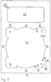
- Fig. 5 shows a casing for a chimney with an additional almost rectangular air shaft (28), as it is used for the removal of the boiler room air or for the supply of combustion air in air-exhaust systems.
- a further recess (32) is arranged in the region of the air shaft (28) (upper left corner of FIG. 5).
- the recess (32) is configured in the same way as the recess (6) in the region of the chimney draft (44) with regard to arrangement and wall thickness.
- Flow channels (4) are shown in the area of the chimney draft (44), two of which are arranged in the corner areas of the casing (right and left lower corner of FIG. 5). Two further flow channels (4) are arranged in corner areas between the round chimney draft and the adjacent, almost rectangular air duct, whereby between the chimney draft and a continuous wall (30) extends to the air shaft.
- the lateral boundary surfaces (16) run at an angle of 135 ° to the adjacent wall, since in this area there is no reduction in the cross section of the flow channels through recesses. It can be seen here that the additional space gained through the vertical arrangement of the lateral boundary surface, as shown in the lower right corner of FIG. 5, largely compensates for the loss of space due to the recess with the same opening width to the insulation layer.
Landscapes
- Engineering & Computer Science (AREA)
- Architecture (AREA)
- Civil Engineering (AREA)
- Structural Engineering (AREA)
- Chimneys And Flues (AREA)
- Working Measures On Existing Buildindgs (AREA)
- Joining Of Building Structures In Genera (AREA)
- Forms Removed On Construction Sites Or Auxiliary Members Thereof (AREA)
- Rod-Shaped Construction Members (AREA)
- Laminated Bodies (AREA)
- Movable Scaffolding (AREA)
Applications Claiming Priority (2)
| Application Number | Priority Date | Filing Date | Title |
|---|---|---|---|
| DE9012119U | 1990-08-23 | ||
| DE9012119U DE9012119U1 (de) | 1990-08-23 | 1990-08-23 | Mantelstein für mehrschalige Hausschornsteine |
Publications (3)
| Publication Number | Publication Date |
|---|---|
| EP0473982A2 true EP0473982A2 (fr) | 1992-03-11 |
| EP0473982A3 EP0473982A3 (en) | 1992-07-01 |
| EP0473982B1 EP0473982B1 (fr) | 1994-12-07 |
Family
ID=6856762
Family Applications (1)
| Application Number | Title | Priority Date | Filing Date |
|---|---|---|---|
| EP91113588A Expired - Lifetime EP0473982B1 (fr) | 1990-08-23 | 1991-08-13 | Pierre de manteau de cheminée pour cheminées domestiques |
Country Status (3)
| Country | Link |
|---|---|
| EP (1) | EP0473982B1 (fr) |
| AT (1) | ATE115224T1 (fr) |
| DE (2) | DE9012119U1 (fr) |
Cited By (6)
| Publication number | Priority date | Publication date | Assignee | Title |
|---|---|---|---|---|
| US5640851A (en) * | 1993-05-24 | 1997-06-24 | Rolls-Royce Plc | Gas turbine engine combustion chamber |
| EP0657015B2 (fr) † | 1992-09-04 | 1999-08-04 | BRAAS GmbH | Embase de cheminee |
| FR2788073A1 (fr) * | 1999-01-05 | 2000-07-07 | Ind Regionale Batiment | Conduit de cheminee ainsi que des boisseaux de cheminee utilisables pour realiser un tel conduit |
| GB2358457A (en) * | 1999-12-23 | 2001-07-25 | Dunbrik | Gas flue block system |
| US6285704B1 (en) | 1997-07-14 | 2001-09-04 | Mitel Semiconductor Ab | Field modulated vertical cavity surface-emitting laser with internal optical pumping |
| WO2012156321A1 (fr) * | 2011-05-18 | 2012-11-22 | F. Holzer Gmbh | Corps moulé à action antibactérienne, procédé de stérilisation de formulations, contenant de stockage comprenant ledit corps moulé et utilisation de ce contenant de stockage |
Families Citing this family (3)
| Publication number | Priority date | Publication date | Assignee | Title |
|---|---|---|---|---|
| DE4418872C2 (de) * | 1994-05-30 | 1999-02-04 | Venus Max Sen | Schachtbauelement und daraus hergestellte Schächte oder Kaminkonstruktionen |
| CN104234387B (zh) * | 2014-09-28 | 2017-07-28 | 张琦 | 薄壁管 |
| CN104234386B (zh) * | 2014-09-28 | 2017-07-28 | 张琦 | 薄壁管件 |
Family Cites Families (5)
| Publication number | Priority date | Publication date | Assignee | Title |
|---|---|---|---|---|
| GB817072A (en) * | 1954-05-19 | 1959-07-22 | Eric Macintyre Gray | Improvements relating to precast building blocks |
| US1700850A (en) * | 1927-09-30 | 1929-02-05 | Raymond J Moths | Chimney flue |
| AT398106B (de) * | 1981-03-30 | 1994-09-26 | Schiedel Gmbh & Co | Mehrschaliger schornstein |
| CH664618A5 (de) * | 1984-09-07 | 1988-03-15 | Zuercher Ziegeleien | Mehrschaliger schornstein. |
| US4616457A (en) * | 1985-10-04 | 1986-10-14 | Kemstone Manufacturing, Inc. | Enhanced safety flue construction |
-
1990
- 1990-08-23 DE DE9012119U patent/DE9012119U1/de not_active Expired - Lifetime
-
1991
- 1991-08-13 EP EP91113588A patent/EP0473982B1/fr not_active Expired - Lifetime
- 1991-08-13 AT AT91113588T patent/ATE115224T1/de not_active IP Right Cessation
- 1991-08-13 DE DE59103776T patent/DE59103776D1/de not_active Expired - Lifetime
Cited By (10)
| Publication number | Priority date | Publication date | Assignee | Title |
|---|---|---|---|---|
| EP0657015B2 (fr) † | 1992-09-04 | 1999-08-04 | BRAAS GmbH | Embase de cheminee |
| US5640851A (en) * | 1993-05-24 | 1997-06-24 | Rolls-Royce Plc | Gas turbine engine combustion chamber |
| US6285704B1 (en) | 1997-07-14 | 2001-09-04 | Mitel Semiconductor Ab | Field modulated vertical cavity surface-emitting laser with internal optical pumping |
| FR2788073A1 (fr) * | 1999-01-05 | 2000-07-07 | Ind Regionale Batiment | Conduit de cheminee ainsi que des boisseaux de cheminee utilisables pour realiser un tel conduit |
| EP1018584A1 (fr) * | 1999-01-05 | 2000-07-12 | L'industrielle Regionale Du Batiment | Conduit de cheminée ainsi que boisseau de cheminée utilisable pour réaliser un tel conduit |
| GB2358457A (en) * | 1999-12-23 | 2001-07-25 | Dunbrik | Gas flue block system |
| GB2358457B (en) * | 1999-12-23 | 2004-07-28 | Dunbrik | Gas flue block system |
| WO2012156321A1 (fr) * | 2011-05-18 | 2012-11-22 | F. Holzer Gmbh | Corps moulé à action antibactérienne, procédé de stérilisation de formulations, contenant de stockage comprenant ledit corps moulé et utilisation de ce contenant de stockage |
| CN103635083A (zh) * | 2011-05-18 | 2014-03-12 | F·霍尔泽股份有限公司 | 起抗菌作用的模塑制品,用于制剂灭菌的方法,含有所述模塑制品的储存容器以及储存容器的用途 |
| CN103635083B (zh) * | 2011-05-18 | 2018-04-27 | F·霍尔泽股份有限公司 | 起抗菌作用的模塑制品,用于制剂灭菌的方法,含有所述模塑制品的储存容器以及储存容器的用途 |
Also Published As
| Publication number | Publication date |
|---|---|
| EP0473982A3 (en) | 1992-07-01 |
| DE9012119U1 (de) | 1991-12-19 |
| DE59103776D1 (de) | 1995-01-19 |
| ATE115224T1 (de) | 1994-12-15 |
| EP0473982B1 (fr) | 1994-12-07 |
Similar Documents
| Publication | Publication Date | Title |
|---|---|---|
| DE3711222A1 (de) | Rahmenkonstruktion | |
| EP0473982B1 (fr) | Pierre de manteau de cheminée pour cheminées domestiques | |
| DE2456379A1 (de) | Druckbehaelter, insbesondere kernreaktordruckbehaelter | |
| CH685805A5 (de) | Filterplatte. | |
| EP1849738B1 (fr) | Arrangement d'une paroi d'une cabine d'ascenseur. | |
| AT246007B (de) | Feuerfeste aufrechte Ausmauerung für etwa zylindrische oder teilzylindrische Hohlräume | |
| DE69004954T2 (de) | Ausbildung einer eckfuge für baueinheiten aus stein. | |
| DE3632890C2 (fr) | ||
| EP0440177B1 (fr) | Coffrage pour construction en béton | |
| DE2436547A1 (de) | Stangenfoermiges bauelement | |
| WO1993024933A1 (fr) | Faisceau d'elements combustibles de reacteur nucleaire avec ecarteur hexagonal constitue d'un assemblage d'elements de base | |
| EP0209815A2 (fr) | Pierre de manteau de cheminée pour cheminées multicorps | |
| DE102004010936A1 (de) | Schichtenspeicher mit einem Gehäuse und einer Isolierung | |
| DE2646116B2 (de) | Saugwalze für Papiermaschinen | |
| DE1509894B1 (de) | Mantelstein mit rundem Querschnitt fuer Kamine mit Einsatzrohr | |
| DE102021109835A1 (de) | Brennerkörper für ein Heizgerät sowie Formkörper und Verfahren zur Herstellung eines Mantels eines Brennerkörpers | |
| DE8027569U1 (de) | Platte, insbesondere deckenplatte aus beton | |
| DE3530762A1 (de) | Regenwasserschacht | |
| DE2911878C2 (de) | Diffusoraufsatz für Ventilatoren von Kühltürmen o.dgl. | |
| DE1519599B2 (fr) | ||
| DE29610779U1 (de) | Baukastensystem zum Herstellen von Bauteilen, insbesondere für den Innen- und Außenausbau | |
| DE1084899B (de) | Kaminformstein | |
| DE2336603A1 (de) | Abdeckungselement | |
| DE3302889A1 (de) | Schornsteinkopf | |
| DE202019102119U1 (de) | Abdeckrost |
Legal Events
| Date | Code | Title | Description |
|---|---|---|---|
| PUAI | Public reference made under article 153(3) epc to a published international application that has entered the european phase |
Free format text: ORIGINAL CODE: 0009012 |
|
| AK | Designated contracting states |
Kind code of ref document: A2 Designated state(s): AT CH DE LI |
|
| PUAL | Search report despatched |
Free format text: ORIGINAL CODE: 0009013 |
|
| AK | Designated contracting states |
Kind code of ref document: A3 Designated state(s): AT CH DE LI |
|
| 17P | Request for examination filed |
Effective date: 19921214 |
|
| 17Q | First examination report despatched |
Effective date: 19930901 |
|
| GRAA | (expected) grant |
Free format text: ORIGINAL CODE: 0009210 |
|
| AK | Designated contracting states |
Kind code of ref document: B1 Designated state(s): AT CH DE LI |
|
| REF | Corresponds to: |
Ref document number: 115224 Country of ref document: AT Date of ref document: 19941215 Kind code of ref document: T |
|
| REF | Corresponds to: |
Ref document number: 59103776 Country of ref document: DE Date of ref document: 19950119 |
|
| PLBE | No opposition filed within time limit |
Free format text: ORIGINAL CODE: 0009261 |
|
| STAA | Information on the status of an ep patent application or granted ep patent |
Free format text: STATUS: NO OPPOSITION FILED WITHIN TIME LIMIT |
|
| 26N | No opposition filed | ||
| REG | Reference to a national code |
Ref country code: CH Ref legal event code: PL |
|
| REG | Reference to a national code |
Ref country code: CH Ref legal event code: AEN Free format text: DAS PATENT IST AUFGRUND DES WEITERBEHANDLUNGSANTRAGS VOM 17.05.1996 REAKTIVIERT WORDEN. |
|
| PGFP | Annual fee paid to national office [announced via postgrant information from national office to epo] |
Ref country code: AT Payment date: 19970822 Year of fee payment: 7 |
|
| PGFP | Annual fee paid to national office [announced via postgrant information from national office to epo] |
Ref country code: CH Payment date: 19970827 Year of fee payment: 7 |
|
| PG25 | Lapsed in a contracting state [announced via postgrant information from national office to epo] |
Ref country code: AT Free format text: LAPSE BECAUSE OF NON-PAYMENT OF DUE FEES Effective date: 19980813 |
|
| PG25 | Lapsed in a contracting state [announced via postgrant information from national office to epo] |
Ref country code: CH Free format text: LAPSE BECAUSE OF NON-PAYMENT OF DUE FEES Effective date: 19980831 Ref country code: LI Free format text: LAPSE BECAUSE OF NON-PAYMENT OF DUE FEES Effective date: 19980831 |
|
| REG | Reference to a national code |
Ref country code: CH Ref legal event code: PL |
|
| PGFP | Annual fee paid to national office [announced via postgrant information from national office to epo] |
Ref country code: DE Payment date: 20100831 Year of fee payment: 20 |
|
| REG | Reference to a national code |
Ref country code: DE Ref legal event code: R071 Ref document number: 59103776 Country of ref document: DE |
|
| REG | Reference to a national code |
Ref country code: DE Ref legal event code: R071 Ref document number: 59103776 Country of ref document: DE |
|
| PG25 | Lapsed in a contracting state [announced via postgrant information from national office to epo] |
Ref country code: DE Free format text: LAPSE BECAUSE OF EXPIRATION OF PROTECTION Effective date: 20110814 |