EP0473994A2 - Bouteille déformable avec enveloppe interne - Google Patents
Bouteille déformable avec enveloppe interne Download PDFInfo
- Publication number
- EP0473994A2 EP0473994A2 EP91113727A EP91113727A EP0473994A2 EP 0473994 A2 EP0473994 A2 EP 0473994A2 EP 91113727 A EP91113727 A EP 91113727A EP 91113727 A EP91113727 A EP 91113727A EP 0473994 A2 EP0473994 A2 EP 0473994A2
- Authority
- EP
- European Patent Office
- Prior art keywords
- holder
- packaging according
- opening area
- cross
- opening
- Prior art date
- Legal status (The legal status is an assumption and is not a legal conclusion. Google has not performed a legal analysis and makes no representation as to the accuracy of the status listed.)
- Withdrawn
Links
- 239000000463 material Substances 0.000 claims abstract description 21
- 238000009423 ventilation Methods 0.000 claims abstract description 17
- 238000004806 packaging method and process Methods 0.000 claims description 51
- 238000004026 adhesive bonding Methods 0.000 claims description 2
- 238000003466 welding Methods 0.000 claims description 2
- 238000000605 extraction Methods 0.000 abstract description 2
- 238000007789 sealing Methods 0.000 description 13
- 238000013461 design Methods 0.000 description 8
- 239000012528 membrane Substances 0.000 description 5
- 238000000034 method Methods 0.000 description 4
- 230000006835 compression Effects 0.000 description 3
- 238000007906 compression Methods 0.000 description 3
- 230000000694 effects Effects 0.000 description 3
- 238000005429 filling process Methods 0.000 description 2
- 238000004519 manufacturing process Methods 0.000 description 2
- 230000004323 axial length Effects 0.000 description 1
- 238000004891 communication Methods 0.000 description 1
- 230000007423 decrease Effects 0.000 description 1
- 230000001771 impaired effect Effects 0.000 description 1
- 238000003780 insertion Methods 0.000 description 1
- 230000037431 insertion Effects 0.000 description 1
- 239000003755 preservative agent Substances 0.000 description 1
- 230000000717 retained effect Effects 0.000 description 1
- 238000005070 sampling Methods 0.000 description 1
- 238000013022 venting Methods 0.000 description 1
Images



Classifications
-
- B—PERFORMING OPERATIONS; TRANSPORTING
- B05—SPRAYING OR ATOMISING IN GENERAL; APPLYING FLUENT MATERIALS TO SURFACES, IN GENERAL
- B05B—SPRAYING APPARATUS; ATOMISING APPARATUS; NOZZLES
- B05B11/00—Single-unit hand-held apparatus in which flow of contents is produced by the muscular force of the operator at the moment of use
- B05B11/0005—Components or details
- B05B11/0062—Outlet valves actuated by the pressure of the fluid to be sprayed
- B05B11/0072—A valve member forming part of an outlet opening
-
- B—PERFORMING OPERATIONS; TRANSPORTING
- B05—SPRAYING OR ATOMISING IN GENERAL; APPLYING FLUENT MATERIALS TO SURFACES, IN GENERAL
- B05B—SPRAYING APPARATUS; ATOMISING APPARATUS; NOZZLES
- B05B11/00—Single-unit hand-held apparatus in which flow of contents is produced by the muscular force of the operator at the moment of use
- B05B11/01—Single-unit hand-held apparatus in which flow of contents is produced by the muscular force of the operator at the moment of use characterised by the means producing the flow
- B05B11/04—Deformable containers producing the flow, e.g. squeeze bottles
- B05B11/047—Deformable containers producing the flow, e.g. squeeze bottles characterised by the outlet or venting means
-
- B—PERFORMING OPERATIONS; TRANSPORTING
- B05—SPRAYING OR ATOMISING IN GENERAL; APPLYING FLUENT MATERIALS TO SURFACES, IN GENERAL
- B05B—SPRAYING APPARATUS; ATOMISING APPARATUS; NOZZLES
- B05B11/00—Single-unit hand-held apparatus in which flow of contents is produced by the muscular force of the operator at the moment of use
- B05B11/01—Single-unit hand-held apparatus in which flow of contents is produced by the muscular force of the operator at the moment of use characterised by the means producing the flow
- B05B11/04—Deformable containers producing the flow, e.g. squeeze bottles
- B05B11/048—Deformable containers producing the flow, e.g. squeeze bottles characterised by the container, e.g. this latter being surrounded by an enclosure, or the means for deforming it
-
- B—PERFORMING OPERATIONS; TRANSPORTING
- B65—CONVEYING; PACKING; STORING; HANDLING THIN OR FILAMENTARY MATERIAL
- B65D—CONTAINERS FOR STORAGE OR TRANSPORT OF ARTICLES OR MATERIALS, e.g. BAGS, BARRELS, BOTTLES, BOXES, CANS, CARTONS, CRATES, DRUMS, JARS, TANKS, HOPPERS, FORWARDING CONTAINERS; ACCESSORIES, CLOSURES, OR FITTINGS THEREFOR; PACKAGING ELEMENTS; PACKAGES
- B65D47/00—Closures with filling and discharging, or with discharging, devices
- B65D47/04—Closures with discharging devices other than pumps
- B65D47/20—Closures with discharging devices other than pumps comprising hand-operated members for controlling discharge
- B65D47/2018—Closures with discharging devices other than pumps comprising hand-operated members for controlling discharge comprising a valve or like element which is opened or closed by deformation of the container or closure
- B65D47/2056—Closures with discharging devices other than pumps comprising hand-operated members for controlling discharge comprising a valve or like element which is opened or closed by deformation of the container or closure lift valve type
- B65D47/2081—Closures with discharging devices other than pumps comprising hand-operated members for controlling discharge comprising a valve or like element which is opened or closed by deformation of the container or closure lift valve type in which the deformation raises or lowers the valve port
-
- B—PERFORMING OPERATIONS; TRANSPORTING
- B65—CONVEYING; PACKING; STORING; HANDLING THIN OR FILAMENTARY MATERIAL
- B65D—CONTAINERS FOR STORAGE OR TRANSPORT OF ARTICLES OR MATERIALS, e.g. BAGS, BARRELS, BOTTLES, BOXES, CANS, CARTONS, CRATES, DRUMS, JARS, TANKS, HOPPERS, FORWARDING CONTAINERS; ACCESSORIES, CLOSURES, OR FITTINGS THEREFOR; PACKAGING ELEMENTS; PACKAGES
- B65D83/00—Containers or packages with special means for dispensing contents
- B65D83/771—Containers or packages with special means for dispensing contents for dispensing fluent contents by means of a flexible bag or a deformable membrane or diaphragm
-
- B—PERFORMING OPERATIONS; TRANSPORTING
- B65—CONVEYING; PACKING; STORING; HANDLING THIN OR FILAMENTARY MATERIAL
- B65D—CONTAINERS FOR STORAGE OR TRANSPORT OF ARTICLES OR MATERIALS, e.g. BAGS, BARRELS, BOTTLES, BOXES, CANS, CARTONS, CRATES, DRUMS, JARS, TANKS, HOPPERS, FORWARDING CONTAINERS; ACCESSORIES, CLOSURES, OR FITTINGS THEREFOR; PACKAGING ELEMENTS; PACKAGES
- B65D2205/00—Venting means
Definitions
- the invention relates to a package provided with at least one closable opening, which has an essentially dimensionally stable, but elastically deformable outer container, within which a plastically deformable, bag-like container is arranged to hold the contents.
- the stiffness of the outer container is chosen so that after a compression, in particular by manual compression, the latter receives its original shape again.
- the inner container consists of an easily deformable, e.g. B. foil-like material, so that it can be almost completely collapsed under pressure and thus can be emptied.
- Such packaging is e.g. from EP-PS 0 190 169, to which express reference is made, in which in particular a closure for such packaging is disclosed.
- the closure is arranged at the opening of the outer container and is designed in such a way that it closes off the filling material and the space located between the inner and outer container from the outside atmosphere and the filling material from the intermediate space.
- the closure has two valves, a removal valve and a ventilation valve.
- the removal valve is designed as a one-way valve so that it opens when pressure is exerted on the outer container, so that the filling material which is thereby under pressure can escape.
- the valve also has restoring means so that it closes when the pressure on the outer container decreases, without air coming into contact to a greater extent with the contents remaining in the packaging.
- the ventilation valve is also a one-way valve formed in such a way that air can get into the space between the inner and outer container from the outside when, after removal and release of, for example, manually applied pressure, the outer container returns to its original shape and thus generates a vacuum in the space.
- the filling material in the inner container is immediately compressed and reaches the removal valve through channels arranged within the closure, which valve then opens. If a larger amount of filling material has already been removed from the packaging, the air in the inner and outer container is compressed and compresses the inner container, since it cannot escape through the ventilation valve, thereby compressing the filling material in the direction of the sampling valve is promoted and leaves this.
- the closure can be designed so that the compressed air acts not only on the inner container but also on the restoring means of the removal valve in such a way that the opening process is supported.
- the bag-like inner container will therefore collapse more and more, while reducing its volume, while the interspace is increasingly filled with air.
- the outer shape of the packaging is therefore retained regardless of the volume of the remaining amount of product during the entire period of use in the unloaded state and there is the possibility of removing the same quantity of product through the same amount of pressure on the packaging almost throughout the period of use.
- Another advantage is that the filling material is almost completely sealed off from the outside atmosphere remains, so that a longer shelf life of the product can be achieved even without preservatives.
- the packaging known from EP-PS 0 190 169 has the disadvantage that the bag-like inner container is attached directly to the closure. Filling such a packaging is therefore only possible by introducing the filling material into the inner container through the removal valve after the packaging has been produced, or by filling the inner container before it is fastened to the closure. The latter would have the consequence that, in order to produce the packaging, the filled bag must be passed through an opening in the outer container which must have a larger opening cross section than the bag. This can severely limit the design options for the packaging, which is undesirable in many cases. But also the possibility of filling the packaging through the removal valve after its manufacture is not a satisfactory solution, since the ventilation valve flows through the ventilation valve in the opposite direction to its originally intended opening direction for filling the extraction valve and for venting the air displaced by the filling ought to.
- the invention has for its object to design a packaging of the type described in the introduction so that these disadvantages are avoided.
- the outer container should be able to have an opening which has a smaller cross section than the filled inner container, so that a limitation of the design options of the packaging in this regard is avoided.
- the handling of the bag-like inner container is to be improved when it is being filled and when it is being assembled.
- the invention proposes to provide a holder between the outer container and the closure, to which the bag-like inner container is attached.
- the holder is preferably essentially sleeve-shaped and designed such that its outer shape corresponds at least over a portion of the inner contour of the corresponding portion of the opening area of the outer container so that it can be inserted into it.
- the opening area is designed as a cylindrical, protruding bottle neck, so that the holder essentially has a hollow cylindrical shape.
- the inner container is tightly attached to the end region of the holder facing the inside of the packaging, so that the contents can only be removed from the inner container through an opening in the holder. Furthermore, the holder or the bottle neck receiving it is designed so that there are passages between the wall of the bottle neck and the holder, which are in communication with the space between the inner and outer container.
- the holder is closed by the closure and the outer container e.g. clamped in position by means of a screw connection arranged on the outside of the bottle neck, the closure being designed such that the outer opening of the holder only interacts with the removal valve and the passages between the holder and the neck of the outer container only interact with the ventilation valve.
- the ventilation passages can also be formed, for example, in that the holder has a cross-sectional shape with flattened areas at least over a partial area of its outer surface or has a polygonal cross-sectional shape overall, so that, for example in the case of a circular wall of the bottle neck, free spaces are available as ventilation passages.
- the internal cross-sectional shape of the bottle neck has such flats or is designed as a polygon, for example hexagonal, so that ventilation channels between the bracket and the wall of the bottle neck are also formed with a circular or similar cross-sectional shape of the holder.
- the holder may even be expedient if necessary to fit the holder in a form-fitting manner in the bottle neck, so that on the one hand slipping of the holder into the container and on the other hand twisting of the holder with the inner container attached to it is avoided within the outer container.
- the positive locking against rotation of the holder will be necessary in particular if the inner bag is to be fixed in a certain position relative to the outer container. This is e.g. the case when the outer container has a shape which differs from the circular cross-sectional shape, in which generally no orientation of the inner container is required, e.g. has an elliptical cross-sectional shape.
- Orientation of the inner container will be necessary in particular if the inner container has a cross-sectional shape for better use of space when filled, which essentially corresponds to the inner cross-sectional shape of the outer container, or if e.g. the opening area of the packaging is not arranged centrally on the outer container.
- the positive locking against slipping in can be achieved by at least one radially outward projection on the Inner container facing away from the bracket are effected, so that the resulting cross-sectional dimension of the end region is larger than the inner diameter of the bottle neck.
- the projection can also be designed such that it extends over the entire circumference of the relevant end region or only over partial sections thereof.
- the positive locking against rotation of the bracket can e.g. can be caused by axially extending projections on the wall of the neck of the outer container or on the outer wall of the holder, which engage in corresponding recesses on the surface of the holder or the wall of the bottle neck. It can be particularly expedient for the projections to engage in the recesses which are already provided for ventilation, the number of projections preferably being smaller than the number of recesses, so that the ventilation cross section is not significantly impaired.
- the packaging according to the invention can now be filled in that the filling material is guided into the inner container through the opening of the holder after it has been pushed into the bottle neck with the possibly partially folded inner container.
- the closure is attached, whereby the holder is secured in its position and the packaging is closed.
- This filling process offers significant advantages over the filling process necessary in the prior art.
- the closure remains completely unused until the first removal of the filling material and can be sealed, for example, during its manufacture.
- handling the bag-like inner container has become easier by attaching it to the holder according to the invention, since, for example, automatic handling means can grip the holder more easily than a bag-like container.
- the packaging can now have an opening, the cross section of which is smaller than the cross section of the filled inner container.
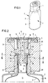
- the packaging designed in the manner of a squeeze bottle, has an inner, easily deformable container 3 and a firmer, but elastic outer container 2, to the bottle-neck-like opening region 17 of which a closure 1 is attached by means of a screw connection 39.
- the inner container 3 is attached with its open end to the lower region 23 of an essentially hollow cylindrical, sleeve-like holder 4 in a sealed manner, for example by gluing or welding.
- the holder 4 has an upper region 25 which is offset from the lower region 23 and has an outer diameter which is larger, the outer diameter of which corresponds to the inner diameter of the bottle neck 17 corresponds so that the holder 4 can be inserted into the bottle neck 17 without noticeable play. According to the above explanation, other shapes are of course also possible.
- the axial length of the holder 4 corresponds approximately to the axial extension of the bottle neck 17, the axial extension of the upper and lower regions 25 and 23 being dimensioned such that on the one hand a stable fit of the holder 4 in the bottle neck 17 is ensured and on the other hand there is enough space for attaching the inner container 3.
- the outer diameter of the lower region 23 of the holder 4 is dimensioned such that, after the bag-like inner container 3 has been attached to the outside of the holder 4 in the installed state, an annular gap 20 remains between the fastening region of the inner container and the wall 19 of the outer container Recesses 26 connects to the space 16 located between the inner container 3 and outer container 2.
- the ring channel 35 is separated from the outside atmosphere by an elastic sealing lip 11 such that air can only flow into the ring channel 35 from the outside atmosphere due to a pressure difference. Ring channel 35 and sealing lip 11 thus form the ventilation valve 7 of the closure 1.
- the sealing lip 11 is part of a membrane body 8 which is fastened in a circumferential groove 6 of the closure 1.
- the membrane body 8 also has a sealing lip 9, which delimits an essentially circular opening 12 and interacts with a pin 41 and an annular channel 13 of the closure 1 and thus forms the removal valve 5 of the closure 1.
- the sealing lip 9 is held by a wall region 10 of the membrane body 8, which has a restoring effect, so that after the removal process, the sealing lip 9 automatically returns to its closed position from its open position (dashed lines).
- the annular channel 13 is connected via the channels 15 to the interior 14 of the inner container 3, in which the filling material is located.
- the arrangement is such that a lower socket 30 of the closure 1 projects into the generally circular opening of the holder 4, the outer diameter of the socket 30 corresponding to the inner diameter of the holder 4, so that a tight connection of the two parts can be effected .
- the socket 30 is delimited by a shoulder 29 which sits on the circumferential projection 21 of the holder 4, wherein a sealing effect between the holder 4 and the closure 1 can also be brought about there. It can be useful to achieve a particularly good tightness or a firm fit of the closure 1 on the bracket 4, the socket 30 and / or the wall of the bracket conical. It may also be expedient to design the inner surface 19 of the bottle neck and / or the outer surface of the upper region 25 of the holder 4 to be conical.
- a seal 43 is provided on the membrane body 8 on an essentially vertical annular web 42, which on an upper nozzle 32, through which the channel 15 also leads, the Closure 1 is applied.
- the seal 43 moves up and down with the sealing lips 8, with an adequate seal between the ring channels 13 and 33 being effected in each position.
- the bottle neck 17 has on its wall 19 axially extending projections 22 which engage in some of the cutouts 26 in the holder 4.
- two projections 22, of which only one is visible in FIG. 3, and six recesses 26 are provided, so that, as described in the introduction, a sufficiently large flow cross section is available. If the inner bag 3 and thus the holder 4 must be fixed with respect to the outer container 2 or the bottle neck 17, it is possible to distribute the projections 22 and the provided recesses 26 of the holder 4 asymmetrically on the respective circumferences, so that only the Bracket 4 can only be pushed into the bottle neck 17 in a certain position.
- the holder 4 is firmly clamped to the outer container 2 by the closure 1 by means of a screw 39 arranged on the outside of the bottle neck 17.
- a circumferential projection 37 is provided, which forms a seal with the lower surface 38 of the closure 1, which separates the channel 31 and thus the intermediate space 16 from the outside atmosphere.
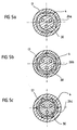
- 5a-g show some exemplary embodiments for outer cross-sectional shapes of the holder 4 or for inner cross-sectional shapes of the opening region 17, in which passages 26a-g are formed when the holder 4 is inserted into the opening region 17.
- the holder 4 is provided with four regular flats, while the cross section of the holder in FIG. 5b corresponds to a regular hexagon.
- axially extending projections are provided on the outer surface of the holder, which abut the inner wall 19 of the opening area while leaving the passages 26c. It is also possible for the surface of the holder to have dome-shaped projections which, in the inserted state of the holder 4, bear against the inner wall 19 of the opening region 17 and to ensure adequate guidance of the holder 4.
- the outer cross-sectional shape of the holder 4 is circular, while the wall 19 of the opening area has flats or projections which bear against the outer surface of the holder. It is of course also possible that on the outside of the holder 4 and / or the inner wall 19 of the opening region 17 side by side on the circumference both flats, projections and recesses are available to z. B. each obtain asymmetrical cross-sectional shapes that allow the insertion of the holder 4 in the opening area 17 only in one position or in predetermined positions.
- the cross-sectional dimension of the holder 4 is selected such that it can be inserted into the opening area 17 while leaving an annular gap 26f.
- the centering of such a bracket in the opening area can, for. B. through the socket 30 of the closure 1 or by an appropriate design of the closure 1 in the area which cooperates with the projection 21 of the holder.
- a positive connection against rotation can be brought about by corresponding projections and / or recesses on the inside of the holder and / or the connector 30 or the projection 21.
- a recess of the bracket 4 is formed larger than the others.
- the outer container 2 is compressed, for example in the direction of the arrows F, with the result that the air in the intermediate space 16 is compressed and the easily deformable inner container 3 is compressed, so that the filling material is held by the holder 4 via the channels 15 and 13 reaches the opening 12, at which it exits. Furthermore, the air compressed in the intermediate space 16 passes through the gap 20, the recesses 26, 27 and the channels 31 into the annular channel 33. There, the air presses against the membrane body 8, which consequently moves upwards, the sealing lip 9 being disengaged comes with the pin 41 and thus supports the opening process of the removal valve 5.
- the sealing lip 9 is brought into its closed position due to the restoring force of the wall area 10, as a result of which the removal valve 5 is closed without air getting into the filling material in a large amount.
- the outer container 2 is returned to its original shape, a negative pressure is created in the intermediate space 16, so that air flows through the sealing lip 11, the channels 35, 34, the cutouts 27, 26 and the gap 20 into the intermediate space 16 due to the prevailing pressure gradient.
- the volume of the inflowing air corresponds at least approximately to the volume of the filling material removed.
Landscapes
- Engineering & Computer Science (AREA)
- Mechanical Engineering (AREA)
- Packages (AREA)
- Containers And Packaging Bodies Having A Special Means To Remove Contents (AREA)
Applications Claiming Priority (2)
| Application Number | Priority Date | Filing Date | Title |
|---|---|---|---|
| DE4027539A DE4027539A1 (de) | 1990-08-31 | 1990-08-31 | Quetschflasche mit innenbeutel |
| DE4027539 | 1990-08-31 |
Publications (2)
| Publication Number | Publication Date |
|---|---|
| EP0473994A2 true EP0473994A2 (fr) | 1992-03-11 |
| EP0473994A3 EP0473994A3 (en) | 1992-03-25 |
Family
ID=6413284
Family Applications (1)
| Application Number | Title | Priority Date | Filing Date |
|---|---|---|---|
| EP19910113727 Withdrawn EP0473994A3 (en) | 1990-08-31 | 1991-08-16 | Squeeze-bottle with internal bag |
Country Status (4)
| Country | Link |
|---|---|
| EP (1) | EP0473994A3 (fr) |
| AU (1) | AU8340991A (fr) |
| CA (1) | CA2049447A1 (fr) |
| DE (1) | DE4027539A1 (fr) |
Cited By (18)
| Publication number | Priority date | Publication date | Assignee | Title |
|---|---|---|---|---|
| WO1993024392A1 (fr) * | 1992-05-22 | 1993-12-09 | Philip Meshberg | Sac ou doublure de barrage inserable pour receptacle de distribution a col etroit et procede de remplissage dudit sac ou de ladite doublure de barrage par le siphon tubulaire |
| US5305810A (en) * | 1992-05-22 | 1994-04-26 | Philip Meshberg | Apparatus and method for filling and dispensing a highly viscous product from a container |
| US5343901A (en) * | 1993-03-17 | 1994-09-06 | Philip Meshberg | Insertable barrier bag or liner for a narrow neck dispensing container and method of filling such a barrier bag or liner |
| ES2064293A1 (es) * | 1993-07-16 | 1995-01-16 | Tuboplast Hispania | Envase tubular no colapsable, dotado de tapon. |
| FR2723356A1 (fr) * | 1994-08-08 | 1996-02-09 | Innovation Rech Plastique Sa | Dispositif de conditionnement d'un produit avec pompe manuelle de distribution en doses unitaires |
| FR2821766A1 (fr) * | 2001-03-07 | 2002-09-13 | Airlessystems | Distributeur de produit cosmetique fluide a poche |
| EP1104252A4 (fr) * | 1998-08-21 | 2002-10-18 | Nouri E Hakim | Recipient a boire antifuite |
| WO2005092144A1 (fr) * | 2004-03-24 | 2005-10-06 | Tag Pack Limited | Dispositif distributeur de liquide |
| FR2872137A1 (fr) * | 2004-06-24 | 2005-12-30 | Thea Sa Lab | Recipient pour le conditionnement d'un liquide a distributeur goutte a goutte, a deformation reversible par admission d'air |
| EP1433534A3 (fr) * | 2002-12-26 | 2006-05-17 | Masatoshi Masuda | Récipient de stockage de fluides |
| US7204386B2 (en) | 1997-08-21 | 2007-04-17 | Hakim Nouri E | No-spill drinking cup apparatus |
| US7243814B2 (en) | 1997-08-21 | 2007-07-17 | Hakim Nouri E | No-spill drinking cup apparatus |
| EP1848656A4 (fr) * | 2005-01-18 | 2009-11-11 | Seaquist Closures Foreign Inc | Element de commande de flux et structure distributrice incorporant celui-ci |
| WO2013053561A1 (fr) * | 2011-10-10 | 2013-04-18 | Unilever N.V. | Ensemble buse |
| WO2014096724A1 (fr) * | 2012-12-20 | 2014-06-26 | Aptar France Sas | Distributeur de produit fluide |
| EP3257783A1 (fr) * | 2016-06-14 | 2017-12-20 | Diatron MI ZRT. | Paquet de réactifs avec un réservoir de déchets intégré |
| EP3984912A1 (fr) * | 2020-10-13 | 2022-04-20 | Henkel AG & Co. KGaA | Dispositif d'application et procédé de fabrication d'un dispositif d'application |
| US12371233B2 (en) | 2020-10-19 | 2025-07-29 | Aptargroup, Inc. | Valve |
Families Citing this family (14)
| Publication number | Priority date | Publication date | Assignee | Title |
|---|---|---|---|---|
| DE9113794U1 (de) * | 1991-11-06 | 1992-01-02 | Dralle GmbH, 2000 Hamburg | Nachfüllbarer Behälter für Flüssigkeiten oder Pulver |
| US5310094A (en) * | 1991-11-15 | 1994-05-10 | Jsp Partners, L.P. | Preservative free sterile fluid dispensing system |
| US5373972A (en) * | 1991-11-15 | 1994-12-20 | Jsp Partners, L.P. | Preservative-free sterile fluid dispensing system |
| DE4219857A1 (de) * | 1992-06-17 | 1993-12-23 | Perfect Ventil Gmbh | Verformbarer Behälter zum Ausbringen von Flüssigkeit |
| JP4443013B2 (ja) * | 2000-08-01 | 2010-03-31 | 花王株式会社 | 二重容器用キャップ |
| DE102010009101A1 (de) * | 2010-02-24 | 2011-08-25 | GAPLAST GmbH, 82442 | Verpackung |
| DE202017002628U1 (de) | 2017-05-16 | 2018-08-17 | Claude Valerius | In seiner Form veränderbares flexibles Behältnis |
| DE102017121333B4 (de) | 2017-09-14 | 2019-03-28 | Linhardt Gmbh & Co. Kg | Behälterverpackung |
| AU2023233598A1 (en) * | 2022-03-18 | 2024-01-18 | Illumina, Inc. | Reagent cartridges and related systems and methods |
| DE102022113841A1 (de) | 2022-06-01 | 2023-12-07 | Inotech Kunststofftechnik Gmbh | Verfahren zum Herstellen eines Spenderbehälters |
| KR20250007636A (ko) | 2022-06-01 | 2025-01-14 | 이노텍 쿤스트슈토프테히닉 게엠바하 | 디스펜서 용기 및 디스펜서 용기의 제조 방법 |
| WO2024217789A1 (fr) | 2023-04-18 | 2024-10-24 | Unilever Ip Holdings B.V. | Capuchon avec soupape pour cartouche |
| DE102023122710B4 (de) | 2023-08-24 | 2026-04-30 | Inotech Kunststofftechnik Gmbh | Spenderbehälter |
| DE102024204162B4 (de) * | 2024-05-03 | 2026-03-19 | Oliver und Manuela Zimmermann GbR (Vertretungsberechtiger Gesellschafter: Oliver Zimmermann, 83454 Anger) | Behälter mit innenbehälter |
Family Cites Families (1)
| Publication number | Priority date | Publication date | Assignee | Title |
|---|---|---|---|---|
| US5025957A (en) * | 1988-10-07 | 1991-06-25 | Ryder International Corp. | Liquid dispenser nozzle assembly |
-
1990
- 1990-08-31 DE DE4027539A patent/DE4027539A1/de not_active Withdrawn
-
1991
- 1991-08-16 EP EP19910113727 patent/EP0473994A3/de not_active Withdrawn
- 1991-08-20 CA CA002049447A patent/CA2049447A1/fr not_active Abandoned
- 1991-08-27 AU AU83409/91A patent/AU8340991A/en not_active Abandoned
Cited By (35)
| Publication number | Priority date | Publication date | Assignee | Title |
|---|---|---|---|---|
| WO1993024392A1 (fr) * | 1992-05-22 | 1993-12-09 | Philip Meshberg | Sac ou doublure de barrage inserable pour receptacle de distribution a col etroit et procede de remplissage dudit sac ou de ladite doublure de barrage par le siphon tubulaire |
| US5460207A (en) * | 1992-05-22 | 1995-10-24 | Meshberg; Philip | Apparatus and method for filling and dispensing a highly viscous product from a container |
| US5305810A (en) * | 1992-05-22 | 1994-04-26 | Philip Meshberg | Apparatus and method for filling and dispensing a highly viscous product from a container |
| USRE36410E (en) * | 1993-03-17 | 1999-11-30 | Meshberg; Philip | Insertable barrier bag or liner for a narrow neck dispensing container and method of filling such a barrier bag of liner |
| US5343901A (en) * | 1993-03-17 | 1994-09-06 | Philip Meshberg | Insertable barrier bag or liner for a narrow neck dispensing container and method of filling such a barrier bag or liner |
| ES2064293A1 (es) * | 1993-07-16 | 1995-01-16 | Tuboplast Hispania | Envase tubular no colapsable, dotado de tapon. |
| FR2723356A1 (fr) * | 1994-08-08 | 1996-02-09 | Innovation Rech Plastique Sa | Dispositif de conditionnement d'un produit avec pompe manuelle de distribution en doses unitaires |
| EP0696479A1 (fr) * | 1994-08-08 | 1996-02-14 | Societe D'innovation Recherche Plastique | Dispositif de conditionnement d'un produit avec pompe manuelle de distribution en doses unitaires |
| US8827107B2 (en) | 1997-08-21 | 2014-09-09 | Luv N' Care, Ltd. | No-spill drinking cup apparatus |
| US7243814B2 (en) | 1997-08-21 | 2007-07-17 | Hakim Nouri E | No-spill drinking cup apparatus |
| USRE43077E1 (en) | 1997-08-21 | 2012-01-10 | Luv N' Care, Ltd. | No-spill drinking cup apparatus |
| US7789263B2 (en) | 1997-08-21 | 2010-09-07 | Luv N' Care, Ltd. | No-spill drinking cup apparatus |
| US7789264B2 (en) | 1997-08-21 | 2010-09-07 | Luv N' Care, Ltd. | No-spill drinking cup apparatus |
| US7204386B2 (en) | 1997-08-21 | 2007-04-17 | Hakim Nouri E | No-spill drinking cup apparatus |
| EP1104252A4 (fr) * | 1998-08-21 | 2002-10-18 | Nouri E Hakim | Recipient a boire antifuite |
| EP1714592A1 (fr) * | 1998-08-21 | 2006-10-25 | Nouri E. Hakim | Recipient a boire antifuite |
| FR2821766A1 (fr) * | 2001-03-07 | 2002-09-13 | Airlessystems | Distributeur de produit cosmetique fluide a poche |
| CN100342982C (zh) * | 2002-12-26 | 2007-10-17 | 增田胜利 | 流体储存容器 |
| US7111763B2 (en) | 2002-12-26 | 2006-09-26 | Masatoshi Masuda | Fluid-storing container |
| EP1433534A3 (fr) * | 2002-12-26 | 2006-05-17 | Masatoshi Masuda | Récipient de stockage de fluides |
| WO2005092144A1 (fr) * | 2004-03-24 | 2005-10-06 | Tag Pack Limited | Dispositif distributeur de liquide |
| FR2872137A1 (fr) * | 2004-06-24 | 2005-12-30 | Thea Sa Lab | Recipient pour le conditionnement d'un liquide a distributeur goutte a goutte, a deformation reversible par admission d'air |
| EP1848656A4 (fr) * | 2005-01-18 | 2009-11-11 | Seaquist Closures Foreign Inc | Element de commande de flux et structure distributrice incorporant celui-ci |
| WO2013053561A1 (fr) * | 2011-10-10 | 2013-04-18 | Unilever N.V. | Ensemble buse |
| WO2014096724A1 (fr) * | 2012-12-20 | 2014-06-26 | Aptar France Sas | Distributeur de produit fluide |
| US20140175123A1 (en) * | 2012-12-20 | 2014-06-26 | Aptar France Sas | Fluid dispenser |
| US9150334B2 (en) | 2012-12-20 | 2015-10-06 | Aptar France Sas | Fluid dispenser |
| WO2017216591A1 (fr) | 2016-06-14 | 2017-12-21 | Diatron Mi Zrt. | Emballage de réactifs comprenant réservoir de déchets intégré |
| EP3257783A1 (fr) * | 2016-06-14 | 2017-12-20 | Diatron MI ZRT. | Paquet de réactifs avec un réservoir de déchets intégré |
| RU2746696C2 (ru) * | 2016-06-14 | 2021-04-19 | Диатрон Ми Зрт. | Контейнер для набора реагентов, интегрированный с резервуаром для отработанного материала |
| US11752502B2 (en) | 2016-06-14 | 2023-09-12 | Diatron Mi Zrt. | Reagent pack with integrated waste reservoir |
| EP3984912A1 (fr) * | 2020-10-13 | 2022-04-20 | Henkel AG & Co. KGaA | Dispositif d'application et procédé de fabrication d'un dispositif d'application |
| WO2022078768A1 (fr) * | 2020-10-13 | 2022-04-21 | Henkel Ag & Co. Kgaa | Dispositif d'application et procédé de production d'un dispositif d'application |
| JP2023546056A (ja) * | 2020-10-13 | 2023-11-01 | ヘンケル・アクチェンゲゼルシャフト・ウント・コムパニー・コマンディットゲゼルシャフト・アウフ・アクチェン | 適用装置及び適用装置の製造方法 |
| US12371233B2 (en) | 2020-10-19 | 2025-07-29 | Aptargroup, Inc. | Valve |
Also Published As
| Publication number | Publication date |
|---|---|
| DE4027539A1 (de) | 1992-03-05 |
| EP0473994A3 (en) | 1992-03-25 |
| CA2049447A1 (fr) | 1992-03-01 |
| AU8340991A (en) | 1992-03-05 |
Similar Documents
| Publication | Publication Date | Title |
|---|---|---|
| EP0473994A2 (fr) | Bouteille déformable avec enveloppe interne | |
| DE69202833T2 (de) | Verstellbares Ventil und Spender mit einem solchen Ventil. | |
| EP0738543B1 (fr) | Pompe de distribution en matière plastique pour matière pâteuse | |
| DE69323867T2 (de) | Beutel mit Pumpschlauch | |
| DE69422976T2 (de) | Ausgabevorrichtung versehen mit einem Rückschlagventil | |
| DE69411494T2 (de) | Abgabevorrichtung mit einer volumenveränderlichen membranartigen Druckkammer | |
| WO1986001489A1 (fr) | Recipient muni d'un obturateur | |
| EP0048931A1 (fr) | Dispositif verseur pour bouteilles | |
| CH660906A5 (de) | Schnellkupplungseinrichtung fuer eine stroemungsleitung. | |
| EP1015340A1 (fr) | Pompe de dispensateur, dispensateur et systeme de bloc-elements pour dispensateur | |
| EP0505611A2 (fr) | Bouteille déformable avec récipient interne | |
| DE3425900C2 (de) | Vorrichtung mit Tropfenzähler zum Abgeben einer flüssigen oder pastösen Substanz | |
| DE60012561T2 (de) | Spender für fliessfähiges material mit einer starren schale und einem flexiblen beutel | |
| WO1998006506A1 (fr) | Systeme permettant d'exprimer une substance coulante d'un sachet tubulaire | |
| DE1632722B2 (de) | Loesbare gas- und fluessigkeitsdichte verbindung zwischen zwei behaeltern, insbesondere zwischen einem aufladebehaelter und dem reservebehaelter eines gasfeuerzeuges | |
| EP0615922A1 (fr) | Cartouche multiple et assemblage | |
| DE69915783T2 (de) | Spender | |
| EP0390974A1 (fr) | Fermeture pour récipient flexible contenant des liquides | |
| EP0224863A2 (fr) | Fermeture avec moyens d'aération intégrés | |
| DE60002861T2 (de) | Abgabevorrichtung für medien | |
| DE69301526T2 (de) | Spenderpumpe | |
| DE2949223C2 (fr) | ||
| DE69210082T2 (de) | Elastischer Spender für viskose Produkte | |
| DE20120142U1 (de) | Sprühdose | |
| EP0719710A2 (fr) | Elément de fixation pour une bouteille en accordéon |
Legal Events
| Date | Code | Title | Description |
|---|---|---|---|
| PUAI | Public reference made under article 153(3) epc to a published international application that has entered the european phase |
Free format text: ORIGINAL CODE: 0009012 |
|
| PUAL | Search report despatched |
Free format text: ORIGINAL CODE: 0009013 |
|
| AK | Designated contracting states |
Kind code of ref document: A2 Designated state(s): AT BE CH DE DK ES FR GB GR IT LI LU NL SE |
|
| AK | Designated contracting states |
Kind code of ref document: A3 Designated state(s): AT BE CH DE DK ES FR GB GR IT LI LU NL SE |
|
| STAA | Information on the status of an ep patent application or granted ep patent |
Free format text: STATUS: THE APPLICATION HAS BEEN WITHDRAWN |
|
| 18W | Application withdrawn |
Withdrawal date: 19920511 |
|
| R18W | Application withdrawn (corrected) |
Effective date: 19920511 |