EP0474085B1 - Multimètre pour mesurer différentes grandeurs selon le choix - Google Patents
Multimètre pour mesurer différentes grandeurs selon le choix Download PDFInfo
- Publication number
- EP0474085B1 EP0474085B1 EP91114283A EP91114283A EP0474085B1 EP 0474085 B1 EP0474085 B1 EP 0474085B1 EP 91114283 A EP91114283 A EP 91114283A EP 91114283 A EP91114283 A EP 91114283A EP 0474085 B1 EP0474085 B1 EP 0474085B1
- Authority
- EP
- European Patent Office
- Prior art keywords
- switch
- input circuit
- measurement
- input
- multimeter
- Prior art date
- Legal status (The legal status is an assumption and is not a legal conclusion. Google has not performed a legal analysis and makes no representation as to the accuracy of the status listed.)
- Expired - Lifetime
Links
Images


Classifications
-
- G—PHYSICS
- G01—MEASURING; TESTING
- G01R—MEASURING ELECTRIC VARIABLES; MEASURING MAGNETIC VARIABLES
- G01R15/00—Details of measuring arrangements of the types provided for in groups G01R17/00 - G01R29/00, G01R33/00 - G01R33/26 or G01R35/00
- G01R15/12—Circuits for multi-testers, i.e. multimeters, e.g. for measuring voltage, current, or impedance at will
Definitions
- the invention relates to a multimeter of the type mentioned in the preamble of claim 1.
- multimeters are very popular in laboratories and workshops, but also among hobbyists.
- a large number of measured variables such as voltages, currents, resistances, levels and frequencies, to name just a few, can be measured with a single device.
- the various input circuits have a first input connection common to all input circuits and a second input connection assigned to the respective measuring circuit and corresponding to the associated measured variable.
- a first input connection common to all input circuits and a second input connection assigned to the respective measuring circuit and corresponding to the associated measured variable.
- the input circuit in this case has a voltage divider on which all voltages are divided down to values or increased by amplification so that values adapted to the measuring system To be available.
- a measuring range switch is used to switch the voltage divider to a desired voltage measuring range or to switch shunts to a desired current measuring range.
- the measuring range switch When operating the measuring device you have to make sure that the measuring range switch is set to the measurand to be measured. At the same time, however, it must be ensured that the measuring leads are connected to the correct input connections on the multimeter on the input side and thus to the correct input circuit.
- the object of the invention is to provide a multimeter according to the preamble of claim 1, which manages with a measuring range switch, which only has to switch very small powers for transmission to the measuring system, and reduces the risk of incorrect operation of the measuring device .
- the multimeter should have at least one input circuit switch, which must also be switched on or over independently of the measurement variable setting made with the aid of the measurement range switch, so that the applied measurement signal reaches the input circuit associated with the specified measurement variable.
- the coupling device is not rigid, but may only go so far as to ensure that the respective input circuit can only be switched on when the measured variable assigned to it corresponds to the measured variable specified at the measuring range switch. Although it is a precisely defined coupling, this enables the input circuit switch on the one hand and the measuring range switch on the other to be switched on or off separately.
- the user of the multimeter is thereby forced to pay more attention, since he has to bring two switches into a switch position that correspond to the measurement quantity he wants.
- the multimeter can only be endangered if both switches are set to the wrong measured variable and the same wrong measured variable.
- the probability of this is much lower than with conventional multimeters, since the user would now have to make two errors, even two identical errors, which is relatively unlikely. As long as he incorrectly sets one of the two switches, there is no match due to the coupling of the two switches and the set input circuit of the multimeter is not switched on.
- the aim of a development of the subject matter of the invention is to prevent the measuring range switch and the input circuit switch from being consciously or unconsciously switched over after a correct selection of the measuring range, and this incorrect operation leads to a risk to the multimeter.
- a locking device is therefore also provided, which enables switching to a different measured variable only after the locking has been released.
- a first locking element will preferably be designed as a locking pin, so that it can then engage in a second locking element, preferably a locking groove, the latter being formed on a movable part of the respective switch which enables switching and thus prevents switching to an impermissible measured variable.
- a second locking element preferably a locking groove, the latter being formed on a movable part of the respective switch which enables switching and thus prevents switching to an impermissible measured variable.
- an input circuit switch which can be operated by hand, it can be mounted in the action area of a movable part of the measuring range switch, preferably a switching wheel belonging to it, and the two switches can be coupled with one another in such a way that the first locking element is formed on the movable part of the input circuit switch, and this on one second locking element formed on a movable part of the measuring range switch engages.
- the input circuit switch As a combined rotary and pressure switch which, by turning, can assume at least two different basic positions, in which it each has a specific input circuit when actuated by pressure switches on.
- the first locking element can penetrate from the basic position of the input circuit switch into various second locking elements associated with the measured variable, preferably grooves in the movable part of the measuring range switch. The lock now ensures that the switches can only be adjusted to a different measured variable when the input circuit switch is switched off.
- first locking elements is expediently coded to the position or type of the second locking elements so that mutual intervention and thus switching on the input circuit switch is only possible if both switches are set to the same measured variable, but are not switched over when the input circuit switch is switched on can.
- the coupling device can also be constructed with the aid of electrical circuits.
- the measuring range switch can be equipped with at least one additional switching path, through which at least one auxiliary circuit is guided, such that when the auxiliary circuit is switched on, a fixed assignment to a specific one is dependent on the switching position of the measuring range switch Input circuit and thus results in a certain measured variable.
- At least one function transmitter can be inserted in the auxiliary circuit, which is activated when the auxiliary circuit is closed by actuation. It depends largely on the type of function generator and the design of the auxiliary circuits, which protection can be achieved with the circuit.
- a protective circuit can be constructed both for multimeters with common input connections for all input circuits and for multimeters with several input connections specific to the different input circuits.
- a contactor into at least one input connection, the contact path of which lies in at least one auxiliary circuit.
- the contactor must be designed so that it contacts when connecting a measuring line and thereby closes the respective auxiliary circuit.
- auxiliary circuit is also switched on or off depending on the position of the measuring range switch, and if it activates a function generator, which in this case can be a signal generator, it is possible to emit an optical or acoustic warning signal if an input circuit is connected to the measuring lines is connected to which a different measured variable is assigned than the measured variable set at the measuring range switch.
- a second function transmitter which may be located in a second auxiliary circuit, can be designed as a magnetic actuator and can be used to actuate the input circuit switch.
- a circuit coupling over certain switching paths of the measuring range switch ensures that at least one input circuit can only be switched on if the measured variable assigned to this input circuit matches the measured variable set on the measuring range switch.
- the magnetic actuator can also operate a locking element in addition to the input circuit switch and an auxiliary circuit switch.
- the locking element can of course also be triggered by a second magnetic actuator. It is essential that the locking element is only activated if the measured variable switched on at the measuring range switch matches the measured variable assigned to the input connection, that is to say the input circuit switch correlates with the assigned connection.
- FIGS. 3 to 6 A purely mechanical coupling between a measuring range switch S and an input circuit switch 9 is shown in FIGS. 3 to 6.
- the two switches are arranged in close spatial proximity to one another, in such a way that the labeling on the control button for the measured variables A to C can be brought into a corresponding position.
- An arrow 13 applied between the two control buttons on the cover plate 11 of the multimeter serves as a reference mark. Both control buttons are thus to be brought into a switch position in which the arrow 13 points to the same measured variable.
- both switches are set to measurand A.
- the three measured variables A to C each have several measuring ranges assigned.
- the coupling between the two switches should act in such a way that the input circuit switch can only be switched on if the arrow 13 points to the same measured variable in both switches. Switching the measuring range switch S between different measuring ranges of the same measured variable A / B or C should, however, be possible despite locking.
- the input circuit switch 9 is constructed as a rotary-pressure switch which has a rotary-pressure element 9a, which must first be brought into a switch position by rotation, in which an input circuit of the multimeter is preselected, which is used to receive the measured variable now located at arrow 13 , in this case the measurand A, is suitable.
- the preselected input circuit is only switched on when the rotary pressure element 9a can be brought into its switched-on position by pressure.
- the first locking element 9c designed as a locking pin
- its position relative to the switch element 10 of the measuring range switch S changes with each rotation of the rotary pressure element 9a to set a different measured variable A to C.
- the second Locking elements 10c in the switch element 10 of the measuring range switch locking grooves are now positioned in such a way that the locking pin 9c can only penetrate into them when both switches have been set to the same measured variable A to C.
- the structure described with two separate switches has the advantage that the possibly large currents in certain input circuits do not have to be switched using the measuring range switch. It is easier to design an input circuit switch with relatively few contacts so that it can handle large currents. In addition, there is no danger to the input circuit switch when switching, since the circuit is always interrupted before switching. Furthermore, the user is forced to pay more attention if he has to put two switches in the correct position and he should make at least two errors when setting the switches, namely, set the same wrong measured variable for both switches before an error occurs.
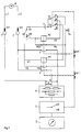
- FIGS. 1, 2 and 7 show electrical circuits in which the protective function is largely achieved by electrical or electromechanical components.
- the mechanical components required for locking the measuring range switch can, as far as the coding of the different measuring ranges is concerned, correspond to the principle shown in FIG. 4.
- the basic circuit diagram shown in Fig. 1 shows a measurement object Q, e.g. a voltage source, which is connected via the measuring lines L1, L2 and connectors ST1, ST2 to input terminals 1, 2 of the multimeter.
- the multimeter has two input circuits a, b with one for both common input connection 1 and specific input connections 2a, 2b assigned to the respective input circuits.
- the different structure of the input circuits a, b is to be illustrated by the measuring range network N, which e.g. can consist of voltage divider resistors for voltage switching or shunts for current switching, and in which the switching is carried out by a measuring range switch S.
- the correspondingly adapted measuring signal then arrives at a measuring system Z, which is used for measurement and display.
- FIG. 2 essentially corresponds to that in FIG. 1 as far as the multimeter structure is concerned, but differs in that instead of several specific input connections 2a, 2b, common input connections 1,2 are provided for all input circuits a, b, so that there is no need to reconnect measuring lines L1, L2.
- an input circuit switch 8 was inserted into the circuit, which can be switched over from a zero position 0 to a measured variable A or B and thus to the input circuits a, b.
- An auxiliary circuit switch HS5 belonging to the input circuit switch 8 or mechanically coupled to it is also switched over from a zero position 0 to a switching position assigned to the measured variable A or B. Together with a magnetic actuator M3 connected in series, a voltage source U and a switching path S1 of the measuring range switch S, it is located in an auxiliary circuit H5.
- the measuring range switch S allows switching between the measured variables A and B on the one hand and between different measuring ranges A1, A2, A3 of the measured variable A and B1, B2 of the measured variable B.
- the position of the switching path S1 which is dependent on the position of the measuring range switch S is with the auxiliary circuit switch HS5 connected in such a way that the magnetic actuator M3 and the lock Ar3 which is dependent on it are activated as soon as the auxiliary circuit switch S5 is switched to a different measurement variable than the measurement variable specified by the measurement range switch S.
- the auxiliary circuit switch HS5 is designed so that it leads the input circuit switch 8 during the switching process and when the switch to an incorrect measured variable the lock Ar3 is still effective in such a way that it prevents the input circuit switch from switching to an incorrect measured variable.
- the measured variable A set on the measuring range switch S corresponds to the measured variable set on the input circuit switch 8. If, however, an attempt is made to switch the input circuit switch 8 to the measured variable B, then the magnetic adjuster M3 and thus the locking device Ar3 would be activated via the leading auxiliary circuit switch HS 5 in such a way that the input circuit switch 8 would have to be switched back to the zero position 0.
- the described mode of operation of the circuit ensures that after specifying a measured variable by the measuring range switch S, only the input circuit a, b can be switched on, to which the same measured variable is assigned. In addition, however, it should be ensured that when the input circuit switch 8 is switched on and the input circuit a or b is closed, the measuring range switch S cannot be switched over to another measured variable.
- This can be achieved with the aid of a second switching path of the auxiliary circuit switch HS5, which, like its first switching path, has a zero position 0, from which one can switch to one of the measured variables A, B.
- a further magnetic actuator M5 is controlled via this second switching path with the aid of the voltage source U of the auxiliary circuit H5.
- a further magnetic actuator M6 is provided, which monitors the measurement signal U e with the aid of an amplifier V and, when it is omitted, resets the input circuit switch 8 to its zero position 0.
- FIG. 1 is a multimeter with several input connections 1, 2a, 2b.
- the two circuit diagrams according to FIGS. 1 and 2 largely agree, which is also illustrated by the same reference numerals.
- the protective circuit is concerned, differences result from the fact that, according to FIG. 1, the input circuits a, b are interrupted or enabled by controlled input circuit switches 6, 7.
- the input circuit switches are actuated again in dependence on the switching position of the measuring range switch S in such a way that only the input circuit switch 6,7 is switched on, which lies in an input circuit a, b to which the measured variable set on the measuring range switch S corresponds.
- This is achieved with two switching paths S2, S3 belonging to the measuring range switch S, which together with a magnetic actuator M1, M2 each lie in an auxiliary circuit H1, H2 and serve to control the respective input circuit switch 6,7.
- the contactors K1, K2 are integrated into the input connections 2a, 2b in such a way that they only close when a plug ST2 is inserted, for example by the connector ST2 meets an insulating cam of the contactor K1, K2, displacing it so far that the contact closes.
- the magnetic actuator M1 can only switch on the input circuit switch 6 if the auxiliary circuit H1 activating it is closed by the contactor K1 when contacting the input connection 2a and the switching path S3 is like the measuring range switch S in one of the measured variables A is in the appropriate position. This ensures that an input current can only flow in an input circuit a, b which is provided for the measurement variable specified at the measuring range switch S.
- auxiliary circuits H3, H4 are therefore constructed in such a way that the signal generator Su is activated whenever an input connection 2a, 2b is contacted, to which a measured variable is assigned which does not correspond to the measured variable set at the measuring range switch S. This prompts the user to change plug S2.
- Another danger is that when the measuring line L2 is correctly connected and the input circuit switch 6, 7 is accordingly closed, the measuring range switch S is consciously or accidentally switched to another measured variable.
- the safety measures described above would take effect, ie the signal transmitter Su would be activated and the input circuit switch of the input circuit concerned would be opened, but the latter is undesirable, at least as long as a high current flows in the input circuit, for example, since in this case the interruption of the circuit contacts the Can endanger input circuit switch.
- a locking device Ar1 assigned to the magnetic actuator M1 and a locking device Ar2 assigned to the magnetic actuator M2 are provided.
- the two detents Ar1 and Ar2 could also be combined, since they both act on the measuring range switch S and lock it as long as one of the two input circuit switches 6, 7 is switched on. This means that the measuring range switch S can only be switched over if the plug ST2 is removed from the currently contacted input connection 2a, 2b to be plugged into another input connection. This ensures that the input circuit switch 6,7 only opens when the input circuit is de-energized.
- the users of multimeters often find it difficult to move the measuring line L2 into another input connection when the measured variable changes. They usually prefer switchers that save them from having to switch.
- the construction of a corresponding circuit analogous to the circuit of FIG. 1 is possible without difficulty.
- the two input connections 2a, 2b have been replaced by a common input connection 2, which is readily permissible since the input circuit switches 6, 7 allow the input circuits a, b to be switched on separately.
- the pressure exerted on the user by the circuit according to FIG. 1, by paying attention to the correct measured variable A, B both when actuating the measuring range switch S and when contacting the measuring line L2, can also be carried out in a corresponding manner with an auxiliary switch SA can be achieved. This takes the place of the contactors K1, K2 according to FIG. 3 and, like the measuring range switch S, must be in a switch position assigned to a specific measured variable A, B.
Landscapes
- Physics & Mathematics (AREA)
- General Physics & Mathematics (AREA)
- Measuring Instrument Details And Bridges, And Automatic Balancing Devices (AREA)
Claims (15)
- Multimètre pour mesurer au choix des grandeurs différentes (A, B) dont les signaux de mesure sont pris en compte par le multimètre en passant par différents circuits d'entrée (a, b) associés chacun à une grandeur à mesurer (A, B) déterminée, la sélection d'une grandeur à mesurer (A, B) déterminée s'effectuant à l'aide d'un sélecteur de gammes de mesure (S) et un sélecteur de circuits d'entrée (6 à 9) qui est inséré dans au moins l'un des circuits d'entrée (a, b) et qui, indépendamment de la sélection de la grandeur à mesurer effectuée à l'aide du sélecteur de gammes de mesure (S), doit en plus être fermé ou commuté afin que le signal de mesure appliqué parvienne dans le circuit d'entrée (a, b) correspondant à la grandeur à mesurer (A, B) présélectionnée, caractérisé par le fait qu'un dispositif de couplage (H, H1, H2, 9b, 10b) non rigide entre le sélecteur de circuits d'entrée (6 à 9) et le sélecteur de gammes de mesure (S) assure que le sélecteur de circuits d'entrée (6 à 9) ne puisse être amené que dans une position de fermeture qui, en ce qui concerne la grandeur à mesurer (A, B) présélectionnée par le circuit d'entrée correspondant (a, b), coïncide avec la grandeur à mesurer (A, B) réglée sur le sélecteur de gammes de mesure (S).
- Multimètre suivant la revendication 1, caractérisé par le fait qu'au moins l'une des positions du sélecteur de circuits d'entrée (6 à 9) et/ou du sélecteur de gammes de mesure (S) est verrouillée de telle manière qu'une commutation sur une autre grandeur à mesurer (A, B) ne soit possible que par neutralisation d'un dispositif de verrouillage (9c, 10c, Ar1-Ar4).
- Multimètre suivant la revendication 2, caractérisé par le fait que le dispositif de verrouillage est réalisé avec des composants mécaniques parmi lesquels un premier élément de verrouillage (9c), de préférence un doigt de verrouillage, pénètre dans un second élément de verrouillage (10c), de préférence une rainure de verrouillage, sur une partie mobile (10) du sélecteur respectif (S, 9), permettant la commutation, et empêche ainsi une commutation sur une grandeur à mesurer (A, B) inadmissible.
- Multimètre suivant au moins l'une des revendications précédentes, caractérisé par le fait que le sélecteur de circuits d'entrée (9) est réalisé sous forme de sélecteur manuel de circuits d'entrée situé dans la zone d'action d'une partie mobile (10) du sélecteur de gammes de mesure (S), de préférence d'une roue de sélecteur (10) et que sur la partie mobile (9a) du sélecteur manuel de circuits d'entrée (9) est formé le premier élément de verrouillage (9c) qui peut entrer en prise avec un second élément de verrouillage (10c) formé sur la partie mobile (10) du sélecteur de gammes de mesure (S).
- Multimètre suivant la revendication 3, caractérisé par le fait que le sélecteur manuel de circuits d'entrée (9) est réalisé sous forme de sélecteur combiné à rotation et à pression qui, par rotation, peut occuper au moins deux positions de base différentes dans lesquelles il ferme et branche, en cas d'actionnement par pression, respectivement un circuit d'entrée déterminé (a, b), et l'élément de verrouillage (9c) peut, à partir de la position de base du sélecteur de circuits d'entrée (9), pénétrer dans différents seconds éléments de verrouillage (10c), de préférence des rainures de verrouillage, qui sont associés à la grandeur à mesurer (A, B) et disposés dans la partie mobile (10) du sélecteur de gammes de mesure (S), de telle manière que les sélecteurs (S, 9) ne puissent être commutés sur une autre grandeur à mesurer que lorsque le sélecteur de circuits d'entrée (9) est en position ouverte.
- Multimètre suivant la revendication 3, caractérisé par le fait que les premier et second éléments de verrouillage (9c, 10c) agissent également comme éléments de couplage et lorsque le verrouillage est supprimé, il n'existe pas non plus de couplage, et la position ou le type du premier élément de verrouillage (9c) est codé par rapport à la position ou le type des seconds éléments de verrouillage de telle manière qu'un engagement réciproque et donc une fermeture du sélecteur de circuits d'entrée ne soit possible que lorsque les deux sélecteurs (S, 9) sont réglés sur la même grandeur à mesurer (A, B), et qu'une commutation ne soit pas possible lorsque le sélecteur de circuits d'entrée (9) est fermé, de préférence par le fait qu'au moins un premier élément de verrouillage (9c) réalisé sous forme de doigt et disposé de façon excentrée assure un positionnement alterné, indépendant de la grandeur à mesurer (A, B, C), et des seconds éléments de verrouillage (10c) réalisés sous la forme de rainures se trouvent en regard de ces doigts de manière que les doigts ne puissent pénétrer dans les rainures correspondantes que lorsque leurs positions coïncident.
- Multimètre suivant la revendication 1 ou 2, caractérisé par le fait que le dispositif de couplage est réalisé avec des circuits électriques et le sélecteur de gammes de mesure (S) comporte au moins un contact (S1-S3) par lequel passe au moins un circuit auxiliaire (S1-S5), de telle manière que lorsque le circuit auxiliaire (H1-H5) est fermé, il s'établit un association fixe, dépendant de la position du sélecteur de gammes de mesure (S), par rapport à un circuit d'entrée déterminé (a, b) et donc par rapport à une grandeur à mesurer (A, B) déterminée, et dans le circuit auxiliaire (H1-H5) se trouve au moins un générateur de fonctions (M1-M4, Su) qui est activé lors de l'actionnement par fermeture du circuit auxiliaire (H1-H5).
- Multimètre suivant la revendication 7, caractérisé par le fait qu'à chaque grandeur à mesurer (A, B) est associé un interrupteur de circuit auxiliaire (HS3-HS5) dont la position est couplée avec la position du sélecteur de circuits d'entrée (6-8).
- Multimètre suivant au moins l'une des revendications précédentes, caractérisé par le fait que différents circuits d'entrée (a, b) sont reliés par au moins un sélecteur de circuits d'entrée (8) agissant en tant que commutateur ou d'interrupteur à deux connexions d'entrée (1, 2) communes à plusieurs grandeurs à mesurer (A, B) ou que des circuits d'entrée (a, b) différents sont reliés à des connexions d'entrée (2a, 2b) différentes qui correspondent respectivement à des grandeurs à mesurer (A, B) déterminées et au moins l'un des circuits d'entrée (a, b) contient un sélecteur de circuits d'entrée (6, 7) agissant en tant que commutateur ou interrupteur.
- Multimètre suivant la revendication 9, caractérisé par le fait qu'à au moins une connexion d'entrée (2a, 2b) est intégré un contacteur (K1, K2) dont le contact se trouve dans au moins un circuit auxiliaire (H1-H4) et qui, lors de la connexion d'une ligne de mesure (L2), est actionné et ferme ainsi le circuit auxiliaire (H1-H4) correspondant.
- Multimètre suivant au moins l'une des revendications précédentes, caractérisé par le fait qu'un premier générateur de fonctions agit comme émetteur de signaux (Su) qui émet un signal avertisseur optique ou acoustique lors de la connexion d'un circuit d'entrée (a, b) auquel est associé une grandeur à mesurer (A, B) autre que la grandeur à mesurer (A, B) réglée sur le sélecteur de gammes de mesure (S).
- Multimètre suivant la revendication 7, caractérisé par le fait qu'un deuxième générateur de fonctions est un actionneur magnétique (M1, M2) qui actionne le sélecteur de circuits d'entrée (6, 7), un couplage de circuit assurant, en passant par des contacts (S1, S2) du sélecteur de gammes de mesure (S), qu'au moins un circuit d'entrée (a, b) ne puisse être branché que lorsque la grandeur à mesurer (A, B) associée à ce circuit d'entrée (a, b) coïncide avec la grandeur à mesurer (A, B) réglée sur le sélecteur de gammes de mesure (S).
- Multimètre suivant la revendication 12, caractérisé par le fait que le deuxième générateur de fonctions (M1, M2) comprend une commande électromagnétique avec changement de position de préférence bistable, qui est déclenchable par des impulsions de fermeture et de coupure et qui actionne, outre le circuit d'entrée (6, 7), également un élément de verrouillage (Ar1, Ar2), ou cela est assuré par un autre actionneur magnétique, et l'élément de verrouillage (Ar1, Ar2) est verrouillé, en cas d'actionnement du sélecteur de gammes de mesure (S), de manière qu'une commutation sur une autre grandeur à mesurer ne soit pas possible, l'élément de verrouillage (Ar1, Ar2) n'étant activé que lorsque la grandeur à mesurer (A, B) sélectionnée sur le sélecteur de gammes de mesure (S) coïncide avec le grandeur à mesurer (A, B) associée à la connexion d'entrée (1, 2).
- Multimètre suivant la revendication 7, caractérisé par le fait qu'un sélecteur de circuits d'entrée (8) actionnable à la main est couplé avec un sélecteur de circuits auxiliaires (HS5) situé dans un circuit auxiliaire (H5), et que les deux sélecteurs sont commutables d'une position zéro (O), selon le sens de commutation, sur une autre grandeur à mesurer (A, B), le sélecteur de circuits auxiliaires (HS5) étant, lors de la commutation sur une grandeur à mesurer (A, B), en avance de manière qu'un actionneur magnétique (M3) situé dans le circuit auxiliaire (H5) bloque, par un verrouillage (Ar3), le sélecteur de circuits d'entrée (8) actionnable à la main, pour empêcher la fermeture lorsque le sélecteur de gammes de mesure (S) se trouve sur une grandeur à mesurer (A, B) différente de celle réglée par le sélecteur de circuits d'entrée (8).
- Multimètre suivant la revendication 2, caractérisé par le fait que le dispositif de verrouillage déclenche le verrouillage des sélecteurs (S, 9) en fonction du signal d'entrée (Ue) du multimètre et que le verrouillage est maintenu de préférence uniquement tant qu'un signal d'entrée (Ue) ayant un niveau minimal est mesurable.
Applications Claiming Priority (2)
| Application Number | Priority Date | Filing Date | Title |
|---|---|---|---|
| DE4027802 | 1990-09-01 | ||
| DE4027802A DE4027802A1 (de) | 1990-09-01 | 1990-09-01 | Multimeter zum wahlweisen messen unterschiedlicher messgroessen |
Publications (3)
| Publication Number | Publication Date |
|---|---|
| EP0474085A2 EP0474085A2 (fr) | 1992-03-11 |
| EP0474085A3 EP0474085A3 (en) | 1992-08-19 |
| EP0474085B1 true EP0474085B1 (fr) | 1995-08-02 |
Family
ID=6413433
Family Applications (1)
| Application Number | Title | Priority Date | Filing Date |
|---|---|---|---|
| EP91114283A Expired - Lifetime EP0474085B1 (fr) | 1990-09-01 | 1991-08-26 | Multimètre pour mesurer différentes grandeurs selon le choix |
Country Status (2)
| Country | Link |
|---|---|
| EP (1) | EP0474085B1 (fr) |
| DE (2) | DE4027802A1 (fr) |
Families Citing this family (3)
| Publication number | Priority date | Publication date | Assignee | Title |
|---|---|---|---|---|
| DE9420949U1 (de) * | 1994-12-30 | 1995-05-18 | Conrad Electronic GmbH, 92242 Hirschau | Handmeßinstrument |
| DE102009033156B4 (de) * | 2009-07-13 | 2013-09-19 | Dspace Digital Signal Processing And Control Engineering Gmbh | Vorrichtung und Verfahren zum Messen und/oder Erzeugen von elektrischen Größen |
| CN106568997B (zh) * | 2016-11-15 | 2019-06-07 | 深圳市鼎阳科技有限公司 | 一种万用表电流量程切换控制方法和装置 |
Family Cites Families (2)
| Publication number | Priority date | Publication date | Assignee | Title |
|---|---|---|---|---|
| GB870627A (en) * | 1957-08-01 | 1961-06-14 | Bush And Rank Cintel Ltd | Improvements in or relating to multi range testing devices |
| DE2458319C3 (de) * | 1974-12-10 | 1980-11-20 | Hartmann & Braun Ag, 6000 Frankfurt | Stufendrehschalter für ein elektrisches Vielfachmeßgerät |
-
1990
- 1990-09-01 DE DE4027802A patent/DE4027802A1/de not_active Withdrawn
-
1991
- 1991-08-26 EP EP91114283A patent/EP0474085B1/fr not_active Expired - Lifetime
- 1991-08-26 DE DE59106127T patent/DE59106127D1/de not_active Expired - Fee Related
Non-Patent Citations (1)
| Title |
|---|
| Funkschau 1970, Heft 20, Seite 2023 :"Normatest"; Schaltplan dazu * |
Also Published As
| Publication number | Publication date |
|---|---|
| EP0474085A2 (fr) | 1992-03-11 |
| DE4027802A1 (de) | 1992-03-05 |
| EP0474085A3 (en) | 1992-08-19 |
| DE59106127D1 (de) | 1995-09-07 |
Similar Documents
| Publication | Publication Date | Title |
|---|---|---|
| EP0474086B1 (fr) | ContrÔleur universel ayant au moins trois raccords d'entrée | |
| EP0285962B1 (fr) | Circuit de contrôle pour un appareil chirurgical à haute fréquence | |
| DE3427517C2 (fr) | ||
| DE4140587A1 (de) | Elektronische steuereinrichtung zum schalten mehrerer elektrischer lasten | |
| EP0847587A1 (fr) | Disjoncteur avec des transformateurs de courant et une memoire d'informations | |
| WO2001065577A1 (fr) | Dispositif de commutation de securite comprenant un premier et un second commutateur d'entree | |
| DE19748640C1 (de) | Stromwandler-Meßtrennklemmenanordnung | |
| EP0474085B1 (fr) | Multimètre pour mesurer différentes grandeurs selon le choix | |
| DE10109864A1 (de) | Sicherheitsschaltvorrichtung | |
| EP0474089A2 (fr) | Contrôleur universel ayant un commutateur de change de mesure | |
| EP0474088B1 (fr) | Procédé pour mesurer des variables différentes et contrÔleur universel pour exécuter le procédé | |
| DE2504717C3 (de) | Miniaturdrehschalter in Kompaktbauweise | |
| DE4413676C1 (de) | Schützsicherheitskombination | |
| DE3632383A1 (de) | Elektrische schaltvorrichtung fuer stromkreise in kraftfahrzeugen | |
| EP0118389B1 (fr) | Appareil de commutation électrique pour la surveillance et la commande de connexions de commutation | |
| DE2159284C3 (de) | Schaltungsanordnung zur überwachung eines elektrischen Signales | |
| DE4218660C1 (de) | Profilzylinderschaltschloß | |
| EP4278371B1 (fr) | Appareil de commutation à réinitialisation manuelle | |
| DE3412325C2 (fr) | ||
| DE2824392C2 (de) | Rangier- und Prüfeinrichtung für mindestens eine Alarmschleife einer Alarmanlage | |
| WO2005078223A1 (fr) | Montage electrique | |
| DE2544184C3 (de) | Schaltungsanordnung für einen Fernsprechapparat | |
| EP0878886B1 (fr) | Debranchement des circuits en série dans des aéroports | |
| DE1094851B (de) | Kontakteinrichtung mit auswechselbarer Kontakteinheit | |
| DE3120640C2 (fr) |
Legal Events
| Date | Code | Title | Description |
|---|---|---|---|
| PUAI | Public reference made under article 153(3) epc to a published international application that has entered the european phase |
Free format text: ORIGINAL CODE: 0009012 |
|
| AK | Designated contracting states |
Kind code of ref document: A2 Designated state(s): DE FR GB IT NL |
|
| PUAL | Search report despatched |
Free format text: ORIGINAL CODE: 0009013 |
|
| AK | Designated contracting states |
Kind code of ref document: A3 Designated state(s): DE FR GB IT NL |
|
| 17P | Request for examination filed |
Effective date: 19921109 |
|
| 17Q | First examination report despatched |
Effective date: 19940520 |
|
| GRAA | (expected) grant |
Free format text: ORIGINAL CODE: 0009210 |
|
| AK | Designated contracting states |
Kind code of ref document: B1 Designated state(s): DE FR GB IT NL |
|
| REF | Corresponds to: |
Ref document number: 59106127 Country of ref document: DE Date of ref document: 19950907 |
|
| GBT | Gb: translation of ep patent filed (gb section 77(6)(a)/1977) |
Effective date: 19950814 |
|
| ET | Fr: translation filed | ||
| ITF | It: translation for a ep patent filed | ||
| PLBE | No opposition filed within time limit |
Free format text: ORIGINAL CODE: 0009261 |
|
| STAA | Information on the status of an ep patent application or granted ep patent |
Free format text: STATUS: NO OPPOSITION FILED WITHIN TIME LIMIT |
|
| PGFP | Annual fee paid to national office [announced via postgrant information from national office to epo] |
Ref country code: NL Payment date: 19960626 Year of fee payment: 6 |
|
| 26N | No opposition filed | ||
| PG25 | Lapsed in a contracting state [announced via postgrant information from national office to epo] |
Ref country code: NL Free format text: LAPSE BECAUSE OF NON-PAYMENT OF DUE FEES Effective date: 19980301 |
|
| NLV4 | Nl: lapsed or anulled due to non-payment of the annual fee |
Effective date: 19980301 |
|
| PGFP | Annual fee paid to national office [announced via postgrant information from national office to epo] |
Ref country code: GB Payment date: 19980810 Year of fee payment: 8 |
|
| PGFP | Annual fee paid to national office [announced via postgrant information from national office to epo] |
Ref country code: FR Payment date: 19980817 Year of fee payment: 8 |
|
| PGFP | Annual fee paid to national office [announced via postgrant information from national office to epo] |
Ref country code: DE Payment date: 19980826 Year of fee payment: 8 |
|
| PG25 | Lapsed in a contracting state [announced via postgrant information from national office to epo] |
Ref country code: GB Free format text: LAPSE BECAUSE OF NON-PAYMENT OF DUE FEES Effective date: 19990826 |
|
| GBPC | Gb: european patent ceased through non-payment of renewal fee |
Effective date: 19990826 |
|
| PG25 | Lapsed in a contracting state [announced via postgrant information from national office to epo] |
Ref country code: FR Free format text: LAPSE BECAUSE OF NON-PAYMENT OF DUE FEES Effective date: 20000428 |
|
| PG25 | Lapsed in a contracting state [announced via postgrant information from national office to epo] |
Ref country code: DE Free format text: LAPSE BECAUSE OF NON-PAYMENT OF DUE FEES Effective date: 20000601 |
|
| REG | Reference to a national code |
Ref country code: FR Ref legal event code: ST |
|
| PG25 | Lapsed in a contracting state [announced via postgrant information from national office to epo] |
Ref country code: IT Free format text: LAPSE BECAUSE OF NON-PAYMENT OF DUE FEES Effective date: 20050826 |