EP0474446A2 - Abrasiver Schneideapparat mit umgekehrter Sägekette mit nach innen gerichteten Schneideelementen - Google Patents
Abrasiver Schneideapparat mit umgekehrter Sägekette mit nach innen gerichteten Schneideelementen Download PDFInfo
- Publication number
- EP0474446A2 EP0474446A2 EP91307993A EP91307993A EP0474446A2 EP 0474446 A2 EP0474446 A2 EP 0474446A2 EP 91307993 A EP91307993 A EP 91307993A EP 91307993 A EP91307993 A EP 91307993A EP 0474446 A2 EP0474446 A2 EP 0474446A2
- Authority
- EP
- European Patent Office
- Prior art keywords
- links
- chain
- cutting
- accordance
- cutting apparatus
- Prior art date
- Legal status (The legal status is an assumption and is not a legal conclusion. Google has not performed a legal analysis and makes no representation as to the accuracy of the status listed.)
- Withdrawn
Links
Images

Classifications
-
- B—PERFORMING OPERATIONS; TRANSPORTING
- B27—WORKING OR PRESERVING WOOD OR SIMILAR MATERIAL; NAILING OR STAPLING MACHINES IN GENERAL
- B27B—SAWS FOR WOOD OR SIMILAR MATERIAL; COMPONENTS OR ACCESSORIES THEREFOR
- B27B33/00—Sawing tools for saw mills, sawing machines, or sawing devices
- B27B33/14—Saw chains
- B27B33/148—Saw chains with means permitting replacement of cutter elements
-
- B—PERFORMING OPERATIONS; TRANSPORTING
- B28—WORKING CEMENT, CLAY, OR STONE
- B28D—WORKING STONE OR STONE-LIKE MATERIALS
- B28D1/00—Working stone or stone-like materials, e.g. brick, concrete or glass, not provided for elsewhere; Machines, devices, tools therefor
- B28D1/02—Working stone or stone-like materials, e.g. brick, concrete or glass, not provided for elsewhere; Machines, devices, tools therefor by sawing
- B28D1/08—Working stone or stone-like materials, e.g. brick, concrete or glass, not provided for elsewhere; Machines, devices, tools therefor by sawing with saw-blades of endless cutter-type, e.g. chain saws, i.e. saw chains, strap saws
- B28D1/082—Working stone or stone-like materials, e.g. brick, concrete or glass, not provided for elsewhere; Machines, devices, tools therefor by sawing with saw-blades of endless cutter-type, e.g. chain saws, i.e. saw chains, strap saws consisting of chain saws
-
- B—PERFORMING OPERATIONS; TRANSPORTING
- B28—WORKING CEMENT, CLAY, OR STONE
- B28D—WORKING STONE OR STONE-LIKE MATERIALS
- B28D1/00—Working stone or stone-like materials, e.g. brick, concrete or glass, not provided for elsewhere; Machines, devices, tools therefor
- B28D1/02—Working stone or stone-like materials, e.g. brick, concrete or glass, not provided for elsewhere; Machines, devices, tools therefor by sawing
- B28D1/12—Saw-blades or saw-discs specially adapted for working stone
- B28D1/124—Saw chains; rod-like saw blades; saw cables
Definitions
- the present invention relates generally to abrasive cutting apparatus for cutting of rocks, concrete, masonry and the like by means of a flexible cutting chain having abrasive cutting elements thereon, and in particular to such a cutting chain in which the cutting links are inverted so that the abrasive cutting elements face inwardly during cutting.
- the cutting links are engaged by a motor driven drive pulley for driving the chain during cutting.
- the cutting elements are preferably each fixed on a pair of side cutting links of the chain provided on opposite sides of center links.
- the center links extend outwardly and are engaged by guide pulleys to stabilize the chain against lateral movement and to adjust the tension on the chain.
- the abrasive cutting chain of the present invention avoids the use of a guide bar having a track which is normally employed to guide the movement of a cutting chain.
- the drive sprocket and guide bar used in a chain saw for guiding the movement of the abrasive cutting chain frequently become coated with rock dust or other comminuted material, which causes wear and friction that may unduly load the chain saw motor.
- This rock dust accumulation causes abrasion of the guide bar drive track, drive sprocket, and the chain links resulting in rough running and heating of the guide bar and the chain.
- Such abrasion also results in widening of the guide bar track and wear of the sprocket teeth, which causes the chain to be laterally unstable.
- the rock dust or other comminuted material can penetrate between the chain links causing wear of such links and their pivotal pin connections which may result in chain breakage.
- All of these prior saw chains engage a track on a guide bar and are driven by a drive sprocket, unlike the abrasive cutting chain of the present invention, which wear quickly to cause most of the above-mentioned problems.
- the abrasive cutting apparatus of the present invention eliminates both the guide bar and the usual drive sprocket.
- the prior cutting elements extended outwardly of the chain for cutting in a conventional manner, and are not inverted to face inwardly and to engage a motor driven pulley in the manner of the present invention.
- abrasive cutting of rocks, concrete, masonry and the like is still performed, to a large extent, by abrasive cutting cable or wire employing abrasive cutter elements.
- the abrasive cutter elements are in the form of beads mounted in spaced relationship on a flexible cable or wire by shock absorbing coil springs, as shown in U.S. Patent 4,674,474 of Baril, issued June 23, 1987. This process of cutting rocks and other similar material using abrasive wire has been accepted practice in the stone cutting industry for hundreds of years.
- a chain with pivoted links forms at its looped end an unrestrained parabolic curved cutting path through the rock or other work piece. Cables however have a considerable resistance to bending and develop high stress points when they move along a course which tends to move the cable out of its cutting plane and to cause breakage of the cable.
- the chain is inverted so that its cutter links have their abrasive cutting elements facing inward and such cutting elements are engaged by a motor driven pulley in order to drive the cutting chain.
- the operation of such inverted cutting chain can be improved by causing an outer projection portion on each of the center links of the chain which extends outwardly therefrom to engage a groove in each of a pair of idler pulleys which guide movement of the chain to provide lateral stability during cutting and apply tension to the chain.
- Such improved abrasive cutting chain is assembled in standard lengths which are connected together by releasable connector links that may be disconnected and reconnected manually to provide chain assemblies of many different selected lengths.
- the length of the assembled chain can be changed using the releasable connector links to suit different cutting conditions and to replace broken standard lengths in the field.
- Another object of the invention is to provide such an abrasive cutting apparatus which avoids the above-discussed problems of sprocket wear and chain drive slippage by eliminating the use of a motor driven sprocket for driving the chain, and inverting the cutter links on the chain so that the cutting elements on such cutter links face inwardly and are positioned to engage a motor driven pulley for driving the cutting chain.
- a further object of the invention is to provide such an improved cutting chain with greater lateral stability in which outward projections on some of the links of such chain, such as center links, project outwardly into engagement with grooves in guide pulleys positioned on opposite sides of the upper and lower reaches of the continuous loop of chain.
- An additional object of the invention is to provide such an abrasive cutting chain which is made of a plurality of standard lengths of chain which are connected together by releasable connection links in order to vary the length of the chain assembly or to enable repair and replacement of damaged chain sections in a simple and rapid manner in the field manually.
- Still another object of the invention is to provide such an abrasive cutting chain in which the abrasive cutting elements are fixed to the cutting links of such chain so that such cutting elements wear more evenly and are not lost in the event that the chain breaks but can be reused by repair of the chain.
- a still further object of the invention is to provide such an improved abrasive cutting chain which is capable of cutting a narrower cut through the rock or other hard material than an abrasive cutting cable and the danger of personal injury due to breakage of the chain is greatly reduced.
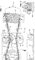
- the abrasive cutting apparatus of the present invention includes an abrasive cutting chain 10.
- the chain 10 has a plurality of cutter links 12 which may be side links positioned upon the opposite side of center links 14.
- the cutter links 12 are inverted so that cutting elements 22 fixed thereto face inward.
- the cutter links are spaced longitudinally apart by coupling links 16 which are also side links but without abrasive cutting elements attached thereto.
- the cutter links 12, center links 14, and coupling links 16 are pivotally coupled together by pivot pins in the form of rivets 18 extending through holes 20 in such links to connect them together and such rivets are provided with enlarged head portions on opposite sides of the chain to hold the rivets in place.
- Each cutter link 12 includes an abrasive cutting element 22 which preferably extends between, and is secured to, a pair of side links 12A on opposite sides of a center link 14 to connect such side links together thereby forming an integral cutting link 12.
- the abrasive cutting element 22 is formed of a matrix of hard abrasive particles such as diamond or silicon carbide particles fixedly secured in a suitable matrix material such as sintered metal powder.
- the abrasive cutting element 22 is fixed to the inner edge of the side links 12A by welding or the like.
- the abrasive cutting element 22 of the cutter link 12 is of a generally rectangular shape and cross-section whose width is slightly wider than the enlarged heads of the rivets 18.
- the cutting elements form a saw cut or kerf 24 of a greater width that the main body of the cutting chain, including the side links 12A and 16, as well as the rivets attaching them to the center links 14. This allows clearance space between the sides of the kerf 24 and the main body of the chain.
- the cutter links 12 are inverted so that the cutting elements 22 of such cutter links face inwardly when they cut the rock or concrete 25.
- the cutting elements ride in a groove 26 in a motor driven pulley 28 which is connected to the output shaft of a motor 29 that drives the chain.
- the groove 26 of the drive pulley 28, may be provided with a resilient liner 30 of rubber or other elastomer material for increased frictional engagement with the cutting element 22 of the cutter links 12 for improved driving efficiency as shown in Figure 3.
- the cutting chain 10 is an endless loop of chain which is pulled through the stone or other hard material 25 by rotation of the drive pulley such as in the clockwise direction shown by arrow 32 in Figure 1.
- the cutting chain 10 is inverted so that outward projections on its center links 14 extend outwardly of the side links to engage guide grooves 38 in a pair of guide and tension pulleys 34 and 36 which may be positioned, respectively, above the upper reach of the chain and below the lower reach of the chain, as shown in Figure 1.
- each of the pulleys 34 and 36 is provided with a narrow rectangular groove 38 into which the center links 14 extend to guide the path of the chain and to provide lateral stability to the chain during cutting by preventing lateral movement of the chain, as shown in Figure 4.
- the pulleys 34 and 36 also are spring or otherwise biased and thereby positioned to provide proper tension on the chain to maintain it in contact with the drive pulley and to enable efficient cutting of the stone or other hard material.
- the endless loop of cutting chain 10 is formed by a plurality of sections of chain of standard lengths which are interconnected by a releasable connection, including a connector pin 40 and a pair of connector links 41 as shown in Figures 2 and 6.
- the connector links which may be rectangular side links are each provided with a circular pin opening 42 which is of slightly greater diameter than enlarged head portions 44 on the opposite ends of the connecting pin 40 so that such connecting pin will pass through such pin opening.
- a pin opening 45 of the approximately same diameter as opening 42 is provided in the center link connected to the connector links 41, and such center link opening may be the same size as the rivet openings in the other center links for rivets 18.
- the connecting pin 40 is provided with a center portion 46 of the same diameter as the two head portions 44, such center portion passing through the pin opening 45 in the center link 14.
- the connecting pin is provided with two grooved intermediate portions 48 of reduced diameter on opposite sides of the center portion 46 between the head portions 44 and such center portion.
- the grooves 48 of the pin are of smaller diameter than the head portions 44 and are of substantially the same width or slightly larger than the thickness of the connecting link 41.
- the connector pin 40 holds the chain sections together, but allows the chain sections to be disconnected manually in the field without the use of special tools when the drive pulley is stopped and the chain is no longer under tension so that the pin holes may be positioned in alignment as shown in Figure 7.
- the connecting pin 40 releasably connects standard length sections of chain together, while allowing such chain sections to be disconnected manually in the field in order to replace broken sections of chain or to change the length of the continuous loop of cutting chain to accommodate different cutting conditions, such as to shorten the chain when the cut is partially done.
- the drive pulley 28 is connected to a drive motor 29 that is mounted on a carriage 50 which travels on wheels 52 along a track 54 to move the drive pulley longitudinally away from the rock or concrete member 25 during cutting until the cut is finished.
- the amount of travel on the track is not sufficient to complete the cut.
- This shortening of the chain can be easily accomplished by removing a standard section of chain using the releasable connection including the connector pin 40 shown in Figures 2 and 6.
- the guide pulleys 34 and 36 are also mounted on the carriage for movement with the drive pulley during cutting. It should be noted that the guide pulleys 34 and 36 are not provided with an elastomer liner within the guide slot 38 of such pulleys, unlike the slot 26 in the drive pulley 28. Also, such guide slots are of much narrower width being only slightly larger that the width of the center links 14. However, the width of the slot 26, including the liner 30 of the drive pulley, must be slightly greater than the width of the cutting element 22 on the cutting links 12.
- the abrasive cutting apparatus of the present invention avoids the use of a guide bar and sprocket, it is not subject to abrasion of these elements by rock dust or other comminuted material like a conventional chain saw.
- the lateral stability of the chain is achieved by engagement of the center links with the grooves 38 of the guide pulleys 34 and 36 which are positioned some distance from the cut 24 so they are not as exposed to rock dust as a guide bar.
- the drive pulley compared to the sprocket of a chain saw.
- cutter links can be employed, like the individual side cutter links of U.S. Patent No. 2,869,534 of Stihl or a chain of uni-link construction where each link of the chain is of the same shape with one end of the link being offset and overlapping the opposite end of the adjacent link which are pivotally connected by rivets. Therefore the scope of the invention should be determined by the following claims.
Landscapes
- Engineering & Computer Science (AREA)
- Mechanical Engineering (AREA)
- Mining & Mineral Resources (AREA)
- Life Sciences & Earth Sciences (AREA)
- Wood Science & Technology (AREA)
- Forests & Forestry (AREA)
- Processing Of Stones Or Stones Resemblance Materials (AREA)
- Finish Polishing, Edge Sharpening, And Grinding By Specific Grinding Devices (AREA)
Applications Claiming Priority (2)
| Application Number | Priority Date | Filing Date | Title |
|---|---|---|---|
| US577258 | 1990-09-04 | ||
| US07/577,258 US5119798A (en) | 1990-09-04 | 1990-09-04 | Abrasive cutting apparatus including inverted cutting chain with inward facing cutting elements |
Publications (2)
| Publication Number | Publication Date |
|---|---|
| EP0474446A2 true EP0474446A2 (de) | 1992-03-11 |
| EP0474446A3 EP0474446A3 (en) | 1992-08-26 |
Family
ID=24307946
Family Applications (1)
| Application Number | Title | Priority Date | Filing Date |
|---|---|---|---|
| EP19910307993 Withdrawn EP0474446A3 (en) | 1990-09-04 | 1991-08-30 | Abrasive cutting apparatus including inverted cutting chain with inward facing cutting elements |
Country Status (5)
| Country | Link |
|---|---|
| US (1) | US5119798A (de) |
| EP (1) | EP0474446A3 (de) |
| JP (1) | JPH04234606A (de) |
| CA (1) | CA2050445A1 (de) |
| ZA (1) | ZA916810B (de) |
Cited By (4)
| Publication number | Priority date | Publication date | Assignee | Title |
|---|---|---|---|---|
| GB2502647A (en) * | 2012-05-31 | 2013-12-04 | Stihl Ag & Co Kg Andreas | Cutting chain with support structures for cutting mineral and metal materials |
| US8869787B2 (en) | 2012-05-31 | 2014-10-28 | Andreas Stihl Ag & Co. Kg | Hand-operated implement comprising a cutting chain for cutting mineral and metal materials |
| US9138912B2 (en) | 2012-05-31 | 2015-09-22 | Andreas Stihl Ag & Co. Kg | Power tool with sprocket cover |
| CN110791638A (zh) * | 2019-11-23 | 2020-02-14 | 安吉长虹制链有限公司 | 一种拖车链加工工艺 |
Families Citing this family (9)
| Publication number | Priority date | Publication date | Assignee | Title |
|---|---|---|---|---|
| DE10226407A1 (de) * | 2002-06-13 | 2003-12-24 | Boegl Max Bauunternehmung Gmbh | Verfahren und Vorrichtung zur Herstellung eines präzisen Betonfertigteiles |
| US7185437B2 (en) * | 2002-11-15 | 2007-03-06 | Carlton Company | Chainsaw bar tensioning apparatus |
| US8651005B2 (en) * | 2008-07-09 | 2014-02-18 | Blount, Inc. | Utility chain cutter |
| CN102205561A (zh) * | 2011-05-10 | 2011-10-05 | 山东大学 | 一种可同时张紧多根绳带的张紧装置 |
| CN107310049A (zh) * | 2017-07-07 | 2017-11-03 | 厦门致力金刚石科技股份有限公司 | 一种金刚石链锯及成型方法 |
| SE543428C2 (en) * | 2019-06-24 | 2021-02-16 | Husqvarna Ab | A rotatable cutting chain work tool, a wall saw arrangement comprising such a work tool, an annular member and a method for producing an annular member |
| CN116291514B (zh) * | 2023-04-13 | 2026-04-10 | 中铁工程装备集团有限公司 | 掘进机械 |
| USD1094051S1 (en) | 2023-10-04 | 2025-09-23 | Oregon Tool, Inc. | Cutting elements for a chainsaw chain |
| USD1116690S1 (en) | 2024-10-03 | 2026-03-10 | Oregon Tool, Inc. | Cutting elements for chainsaw chain |
Family Cites Families (8)
| Publication number | Priority date | Publication date | Assignee | Title |
|---|---|---|---|---|
| FR532069A (fr) * | 1921-03-03 | 1922-01-27 | Appareil destiné à l'abatage des arbres sur pied et au tronçonnement des grumes | |
| US2085756A (en) * | 1934-11-12 | 1937-07-06 | Sullivan Machinery Co | Mining apparatus |
| US2696228A (en) * | 1949-05-04 | 1954-12-07 | Richard G Bowen | Cutting cable for power saws |
| US2869534A (en) * | 1956-09-11 | 1959-01-20 | Stihl Andreas | Grinding chain tool |
| US3204672A (en) * | 1962-01-04 | 1965-09-07 | Remington Arms Co Inc | Saw chain connection |
| JPH049138Y2 (de) * | 1986-04-12 | 1992-03-06 | ||
| US4920947A (en) * | 1988-04-14 | 1990-05-01 | Blount, Inc. | Chain saw components and system for cutting masonry and the like |
| DE69024165T2 (de) * | 1989-09-22 | 1996-05-30 | Mitsubishi Materials Corp | Schneidkette |
-
1990
- 1990-09-04 US US07/577,258 patent/US5119798A/en not_active Expired - Fee Related
-
1991
- 1991-08-28 ZA ZA916810A patent/ZA916810B/xx unknown
- 1991-08-30 EP EP19910307993 patent/EP0474446A3/en not_active Withdrawn
- 1991-08-30 CA CA002050445A patent/CA2050445A1/en not_active Abandoned
- 1991-09-03 JP JP3223069A patent/JPH04234606A/ja active Pending
Cited By (4)
| Publication number | Priority date | Publication date | Assignee | Title |
|---|---|---|---|---|
| GB2502647A (en) * | 2012-05-31 | 2013-12-04 | Stihl Ag & Co Kg Andreas | Cutting chain with support structures for cutting mineral and metal materials |
| US8869787B2 (en) | 2012-05-31 | 2014-10-28 | Andreas Stihl Ag & Co. Kg | Hand-operated implement comprising a cutting chain for cutting mineral and metal materials |
| US9138912B2 (en) | 2012-05-31 | 2015-09-22 | Andreas Stihl Ag & Co. Kg | Power tool with sprocket cover |
| CN110791638A (zh) * | 2019-11-23 | 2020-02-14 | 安吉长虹制链有限公司 | 一种拖车链加工工艺 |
Also Published As
| Publication number | Publication date |
|---|---|
| ZA916810B (en) | 1992-05-27 |
| CA2050445A1 (en) | 1992-03-05 |
| JPH04234606A (ja) | 1992-08-24 |
| EP0474446A3 (en) | 1992-08-26 |
| US5119798A (en) | 1992-06-09 |
Similar Documents
| Publication | Publication Date | Title |
|---|---|---|
| US5119798A (en) | Abrasive cutting apparatus including inverted cutting chain with inward facing cutting elements | |
| US5184598A (en) | Saw chain for aggregate materials | |
| US4920947A (en) | Chain saw components and system for cutting masonry and the like | |
| US3604755A (en) | Cutter bar, cutter chain and sprocket assembly | |
| US6178960B1 (en) | Hand-held motor-driven saw | |
| US5603311A (en) | Belt based cutting system | |
| CA2697300C (en) | Aggregate cutting saw chain | |
| US20120132051A1 (en) | Saw Chain For Aggregate Materials | |
| US6112739A (en) | Method for high speed cutting | |
| CN103402718A (zh) | 链节磨锐方法和装置 | |
| US5136783A (en) | Chain saw sprocket | |
| US5918586A (en) | High speed cutting belt | |
| US3155225A (en) | Lateral plate pusher-type conveyor | |
| EP1093714A1 (de) | Kettensägehalter und -schwertanordnung für eine Baumerntemaschine | |
| US4941315A (en) | Wear resistant chain for trenchers | |
| EP0423501B1 (de) | Schneidkette | |
| US6141892A (en) | Apparatus for limiting chain wear | |
| US3651626A (en) | Power transmission belts | |
| CA1070956A (en) | Power transmission belt | |
| JPH1179350A (ja) | ベルトコンベヤの駆動プーリ | |
| WO2001023128A1 (en) | Non-lubricated chainsaw blade | |
| US2068984A (en) | Cutter chain and bar | |
| CN121194846A (zh) | 用于锯链的锉削工具 | |
| JP2727711B2 (ja) | 平板状チェーン体 | |
| WO2023135447A1 (en) | Two-in-one filing equipment |
Legal Events
| Date | Code | Title | Description |
|---|---|---|---|
| PUAI | Public reference made under article 153(3) epc to a published international application that has entered the european phase |
Free format text: ORIGINAL CODE: 0009012 |
|
| AK | Designated contracting states |
Kind code of ref document: A2 Designated state(s): CH DE FR GB IT LI |
|
| PUAL | Search report despatched |
Free format text: ORIGINAL CODE: 0009013 |
|
| AK | Designated contracting states |
Kind code of ref document: A3 Designated state(s): CH DE FR GB IT LI |
|
| K1C3 | Correction of patent application (complete document) published |
Effective date: 19920311 |
|
| STAA | Information on the status of an ep patent application or granted ep patent |
Free format text: STATUS: THE APPLICATION IS DEEMED TO BE WITHDRAWN |
|
| 18D | Application deemed to be withdrawn |
Effective date: 19930227 |