EP0474544A1 - Verstärkung für Metallbehälter - Google Patents
Verstärkung für Metallbehälter Download PDFInfo
- Publication number
- EP0474544A1 EP0474544A1 EP19910402335 EP91402335A EP0474544A1 EP 0474544 A1 EP0474544 A1 EP 0474544A1 EP 19910402335 EP19910402335 EP 19910402335 EP 91402335 A EP91402335 A EP 91402335A EP 0474544 A1 EP0474544 A1 EP 0474544A1
- Authority
- EP
- European Patent Office
- Prior art keywords
- crown
- skirt
- rib
- peripheral
- reinforcement device
- Prior art date
- Legal status (The legal status is an assumption and is not a legal conclusion. Google has not performed a legal analysis and makes no representation as to the accuracy of the status listed.)
- Ceased
Links
- 239000002184 metal Substances 0.000 title claims abstract description 14
- 230000003014 reinforcing effect Effects 0.000 title abstract description 6
- 238000004806 packaging method and process Methods 0.000 claims description 18
- 230000002093 peripheral effect Effects 0.000 claims description 18
- 230000002787 reinforcement Effects 0.000 claims description 13
- 238000002788 crimping Methods 0.000 claims description 5
- 238000000465 moulding Methods 0.000 claims description 2
- 208000009043 Chemical Burns Diseases 0.000 description 1
- 239000011324 bead Substances 0.000 description 1
- 230000007797 corrosion Effects 0.000 description 1
- 238000005260 corrosion Methods 0.000 description 1
- 239000007788 liquid Substances 0.000 description 1
- 239000000463 material Substances 0.000 description 1
- 230000004048 modification Effects 0.000 description 1
- 238000012986 modification Methods 0.000 description 1
- 235000011837 pasties Nutrition 0.000 description 1
- 230000035939 shock Effects 0.000 description 1
- 210000003462 vein Anatomy 0.000 description 1
Images


Classifications
-
- B—PERFORMING OPERATIONS; TRANSPORTING
- B65—CONVEYING; PACKING; STORING; HANDLING THIN OR FILAMENTARY MATERIAL
- B65D—CONTAINERS FOR STORAGE OR TRANSPORT OF ARTICLES OR MATERIALS, e.g. BAGS, BARRELS, BOTTLES, BOXES, CANS, CARTONS, CRATES, DRUMS, JARS, TANKS, HOPPERS, FORWARDING CONTAINERS; ACCESSORIES, CLOSURES, OR FITTINGS THEREFOR; PACKAGING ELEMENTS; PACKAGES
- B65D55/00—Accessories for container closures not otherwise provided for
- B65D55/02—Locking devices; Means for discouraging or indicating unauthorised opening or removal of closure
- B65D55/06—Deformable or tearable wires, strings or strips; Use of seals
- B65D55/08—Annular elements encircling container necks
- B65D55/0863—Plastic snap-on cap-like collars having frangible parts
Definitions
- the invention relates to a metal packaging reinforcement device having a cover which fits into the opening of a box body.
- a metal packaging reinforcement device having a cover which fits into the opening of a box body.
- Such a device is more particularly intended for packaging containing liquid or pasty, dangerous and / or polluting products.
- the invention mainly aims to reinforce such metal packaging without making any structural modification to the latter, in particular without increasing the thickness of the metal or changing the conformation of the box body and the cover.
- the invention therefore relates to a metal packaging reinforcement device comprising a box body and a cover fitted into an opening of said box body, characterized in that it essentially consists of a plastic cap comprising at less snap-fitting means capable of cooperating with an outer rib of the edge of said opening and means for breaking said cap, at least substantially transversely in a peripheral crown thereof.
- the central part of the cap is constituted by braces extending between its center and said crown.
- the latter is open to its part lower and internally ribbed to define said latching means.
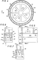
- FIGS. 1 to 3 there is shown a packaging reinforcement device consisting essentially of a cap 11 of semi-rigid plastic material, capable of coming to take place, by snap-fastening to the upper part of the packaging 12, that is to say above the opening 13 and the cover 14 of this package.
- the opening edge comprises an outer rib 15 formed by crimping a conventional opening ring 16 with the edge of the box body.
- the cover 14 fits onto this ring.
- the packaging is generally cylindrical or very slightly frustoconical, and therefore the opening 13 and the cover 14 are of circular outline. It is obvious, however, that the invention is aimed at all variants of form, which have the consequence of adapting its principle to other types of boxes.
- the cap 11 here comprises a peripheral crown 20 and its central part is formed by cross-pieces 21, here extending radially between its center and said crown.
- the crown 20 is open on the side provided for nesting and it is ribbed internally and circumferentially to define latching means capable of cooperating with the outer rib 15 for the establishment of the cap.
- it is a simple circumferential rib 22, molded with the inner face of a side skirt 24, here substantially cylindrical, of the crown.
- such a reinforcement device comprises means for breaking the cover 11 substantially transversely at least at the level of the crown 20.
- these means consist of two transverse imprints 26, 28 made in said ring 11 and a tear-off element 30, here a kind of ring, molded with a portion 32 of the ring 11 defined by such fingerprints. It is clear that by pulling on the tearing element, it causes a transverse rupture of the cap. This allows, taking advantage of the relative elasticity thereof, to release the entire cap, before the first opening of the package.
- the inner face of the flat annular wall 33 of the crown carries three small hooks 34 from molding and intended to secure a cover.
- the groove 25 a of the crown 20 a is more precisely delimited by two ribs peripheral devices.
- a first rib 22a extends over substantially the entire circumference of the inner face of the side skirt 24 to the crown (analogously to the rib 22 of the embodiment of Figures 1 and 2) while a second rib 38 protrudes from an annular surface 39 of the crown, substantially parallel to said skirt.
- This rigidity is increased by the fact that the crown has, externally, stiffening cells 42 adjacent and extending over its entire periphery.
- a third peripheral rib 44 projects from the internal face of the annular surface 39, substantially parallel to the skirt and at a shorter radial distance than said second peripheral rib. This rib 44 is shaped, positioned and dimensioned to engage in a groove 45 of the cover.
- the central part of the cap is constituted by braces 21a here extending radially between the center and the said ring.
- the means for breaking the cover are arranged to, firstly, break the cover transversely by individualizing a tearing element in said side skirt and then, in a second step, cut the side skirt in the direction circumferential to release the outer rib from the metal packaging, that is to say here the crimping rib 15 a .
- the lateral skirt 24 a of the ring is provided with two grooves 61, 62 straight, parallel and spaced, extending Introducememnt with the axial direction of the crown.
- the groove 61 extends over the entire height of the skirt while the groove 62 extends over only the "upper" part thereof.
- a cavity 64 obliquely crossing the wall of the skirt and through which it is possible to introduce a tool such as a screwdriver, to break the side skirt along the two grooves.
- small cells 65 extend circumferentially in the thickness of the skirt, defining a circular cutting contour at the lower end of the groove 62.
- the rib 22 a is interrupted between the two grooves.
- FIG. 8 to 11 is more particularly intended for metal packaging 12 b the opening edge of which has a special outer roll defined in the box body itself.
- This type of roll known per se, is suitable for receiving a cover 14 b .
- This package therefore does not have a crimped opening ring but nevertheless has an outer rib 15 b (in this case the outer roll mentioned above, supplemented by the edge of the cover) usable for mounting the cover 11 b .
- the latter is composed as above of a peripheral crown 20 b and cross bars 21 b .
- the ring 20 b is open and provided with a side skirt 24b here substantially cylindrical.
- the ring has openings 50 extending substantially over part of the height of the side skirt 24b and radially on a small portion of its top wall.
- the "lower" part 52 of the skirt that is to say extending axially beyond the openings 50, is continuous and carries teeth 54.
- Each tooth, forming part of the latching means, is inclined towards inside a corresponding window 50, towards the upper part of the cap.
- the internal face of the skirt is provided with a peripheral rib 22 b, but this is segmented by the presence of the openings 50. All these structural elements therefore delimit a peripheral groove 25 b .
- the internal face of the crown also carries a peripheral rib 44 b projecting substantially parallel to the side skirt 24 b .
- This rib is increased by a plurality of small segments 58 extending substantially radially.
- Such a rib is positioned, shaped and dimensioned to engage in a groove 45b of the cover.
- the profile of the segments is more particularly adapted to that of such a groove.
- the tear-off element 30 b has the shape of a sort of "ring", with an approximately triangular outline, attached to a portion 32 b of the crown 11 b delimited by two transverse imprints 26 b , 28 b .
- raised segments 59 extending circumferentially, allow the stackability of packages equipped with their reinforcing devices.
Landscapes
- Engineering & Computer Science (AREA)
- Mechanical Engineering (AREA)
- Closures For Containers (AREA)
Applications Claiming Priority (2)
| Application Number | Priority Date | Filing Date | Title |
|---|---|---|---|
| FR9011015 | 1990-09-05 | ||
| FR909011015A FR2666306B1 (fr) | 1990-09-05 | 1990-09-05 | Dispositif de renforcement d'emballage metallique. |
Publications (1)
| Publication Number | Publication Date |
|---|---|
| EP0474544A1 true EP0474544A1 (de) | 1992-03-11 |
Family
ID=9400087
Family Applications (1)
| Application Number | Title | Priority Date | Filing Date |
|---|---|---|---|
| EP19910402335 Ceased EP0474544A1 (de) | 1990-09-05 | 1991-08-30 | Verstärkung für Metallbehälter |
Country Status (3)
| Country | Link |
|---|---|
| EP (1) | EP0474544A1 (de) |
| FR (1) | FR2666306B1 (de) |
| ZA (1) | ZA917024B (de) |
Cited By (5)
| Publication number | Priority date | Publication date | Assignee | Title |
|---|---|---|---|---|
| WO1999006297A1 (de) * | 1997-07-28 | 1999-02-11 | INNOCOS INNOVATIVE VERPACKUNGEN FüR DIE KOSMETISCHE INDUSTRIE GMBH | Verschlusskappe mit aufschnappbarem zierring |
| EP1332976A1 (de) * | 2002-01-30 | 2003-08-06 | Metalscatola S.p.a | Vorrichtung zur Lagerung und Handhabung eines luftdichten Behälters |
| EP3868681A1 (de) * | 2020-02-11 | 2021-08-25 | Oregon Precision Industries Inc. d.b.a. Paktech | Sichererheitsbehälterdeckel |
| USD957940S1 (en) | 2020-12-16 | 2022-07-19 | Oregon Precision Industries, Inc. | Secure container cover |
| AU2021200685B2 (en) * | 2020-02-11 | 2023-02-16 | Oregon Precision Industries, Inc. Dba Paktech | Tamper-resistant secure container cover |
Citations (4)
| Publication number | Priority date | Publication date | Assignee | Title |
|---|---|---|---|---|
| DE2334730A1 (de) * | 1972-08-07 | 1974-02-21 | Continental Can Co | Verschluss fuer behaelter |
| DE2405939A1 (de) * | 1973-04-16 | 1974-10-17 | Continental Can Co | Behaelter, insbesondere zum vakuumabdichtenden verschliessen |
| DE8702384U1 (de) * | 1987-02-17 | 1987-05-14 | Hermann Fink, Kunststoff-Spritzgußverarbeitung, 8941 Heimertingen | Schutzkappe zum Aufsetzen auf Faßverschlüsse |
| EP0383745A1 (de) * | 1989-02-17 | 1990-08-22 | Blagden Industries Public Limited Company | Behälter |
-
1990
- 1990-09-05 FR FR909011015A patent/FR2666306B1/fr not_active Expired - Fee Related
-
1991
- 1991-08-30 EP EP19910402335 patent/EP0474544A1/de not_active Ceased
- 1991-09-04 ZA ZA917024A patent/ZA917024B/xx unknown
Patent Citations (4)
| Publication number | Priority date | Publication date | Assignee | Title |
|---|---|---|---|---|
| DE2334730A1 (de) * | 1972-08-07 | 1974-02-21 | Continental Can Co | Verschluss fuer behaelter |
| DE2405939A1 (de) * | 1973-04-16 | 1974-10-17 | Continental Can Co | Behaelter, insbesondere zum vakuumabdichtenden verschliessen |
| DE8702384U1 (de) * | 1987-02-17 | 1987-05-14 | Hermann Fink, Kunststoff-Spritzgußverarbeitung, 8941 Heimertingen | Schutzkappe zum Aufsetzen auf Faßverschlüsse |
| EP0383745A1 (de) * | 1989-02-17 | 1990-08-22 | Blagden Industries Public Limited Company | Behälter |
Cited By (7)
| Publication number | Priority date | Publication date | Assignee | Title |
|---|---|---|---|---|
| WO1999006297A1 (de) * | 1997-07-28 | 1999-02-11 | INNOCOS INNOVATIVE VERPACKUNGEN FüR DIE KOSMETISCHE INDUSTRIE GMBH | Verschlusskappe mit aufschnappbarem zierring |
| EP1332976A1 (de) * | 2002-01-30 | 2003-08-06 | Metalscatola S.p.a | Vorrichtung zur Lagerung und Handhabung eines luftdichten Behälters |
| EP3868681A1 (de) * | 2020-02-11 | 2021-08-25 | Oregon Precision Industries Inc. d.b.a. Paktech | Sichererheitsbehälterdeckel |
| AU2021200685B2 (en) * | 2020-02-11 | 2023-02-16 | Oregon Precision Industries, Inc. Dba Paktech | Tamper-resistant secure container cover |
| US11772863B2 (en) | 2020-02-11 | 2023-10-03 | Oregon Precision Industries, Inc. | Tamper-resistant secure container cover |
| EP4269274A3 (de) * | 2020-02-11 | 2024-03-06 | Oregon Precision Industries Inc. d.b.a. Paktech | Manipulationssicherer sicherer behälterdeckel |
| USD957940S1 (en) | 2020-12-16 | 2022-07-19 | Oregon Precision Industries, Inc. | Secure container cover |
Also Published As
| Publication number | Publication date |
|---|---|
| FR2666306B1 (fr) | 1994-06-24 |
| ZA917024B (en) | 1992-05-27 |
| FR2666306A1 (fr) | 1992-03-06 |
Similar Documents
| Publication | Publication Date | Title |
|---|---|---|
| EP0680887B1 (de) | Verschlusskappe für einen mit einem einzigen Befestigungsflansch versehenen Behälter | |
| EP0682625B1 (de) | Behälterverschluss | |
| FR2563193A1 (fr) | Fermeture de recipient | |
| CH640476A5 (fr) | Bouchon d'un recipient comportant un col. | |
| EP0984889A1 (de) | Verschlusskappe für eine metallische getränkedose | |
| EP2838808A1 (de) | Getränkedosendeckel mit einem klappbaren trinkstutzen | |
| WO2010012947A2 (fr) | Perfectionnement aux couvercles pour contenants, avec anneau d'ouverture | |
| EP0383745B1 (de) | Behälter | |
| EP0953513B1 (de) | Verpackung aus Metall mit Sicherheitskappe | |
| FR2666306A1 (fr) | Dispositif de renforcement d'emballage metallique. | |
| EP1309409B1 (de) | Befestigungselement für eine abgabevorrichtung | |
| FR2665688A1 (fr) | Couvercle en matiere plastique souple pour recipient a bord arrondi. | |
| EP0659147A1 (de) | Trinkbecher zum anbringen an einen getränkebehälter | |
| FR2745794A1 (fr) | Dispositif de bouchage pour un recipient tel qu'en particulier un flacon a usage medical | |
| EP3147231B1 (de) | Verbesserte verpackung für produkt mit innenverpackungsband | |
| FR2474452A1 (fr) | Dispositif de fermeture en particulier pour emballages | |
| FR2563812A1 (fr) | Recipient du type " pot-camion " a ouverture totale. | |
| WO1999010240A2 (fr) | Conditionnement pour produit alimentaire, notamment pour patisserie et produit laitier | |
| FR2539710A1 (fr) | Goulot extensible a paroi annulaire retournable | |
| EP0669177B1 (de) | Metalldose für stürzbaren Inhalt bestehend aus einer Zarge und einem nach Öffnung wiederverschliessbaren Deckel, und Herstellungsverfahren einer solchen Dose | |
| FR2659293A3 (fr) | Emballage forme de deux recipients accoles. | |
| FR2604976A1 (fr) | Emballage metallique, notamment pour produit en poudre et procede de fabrication d'un tel emballage | |
| FR2742417A1 (fr) | Recipient metallique du type boite-boisson | |
| EP0490735B1 (de) | Sehr fester Metalldeckel | |
| FR2804090A1 (fr) | Structure de capsule pour recipient |
Legal Events
| Date | Code | Title | Description |
|---|---|---|---|
| PUAI | Public reference made under article 153(3) epc to a published international application that has entered the european phase |
Free format text: ORIGINAL CODE: 0009012 |
|
| AK | Designated contracting states |
Kind code of ref document: A1 Designated state(s): BE DE DK LU NL SE |
|
| 17P | Request for examination filed |
Effective date: 19920328 |
|
| RAP3 | Party data changed (applicant data changed or rights of an application transferred) |
Owner name: CARNAUDMETALBOX |
|
| 17Q | First examination report despatched |
Effective date: 19930414 |
|
| STAA | Information on the status of an ep patent application or granted ep patent |
Free format text: STATUS: THE APPLICATION HAS BEEN REFUSED |
|
| 18R | Application refused |
Effective date: 19940130 |