EP0474864A1 - Fil de fantaisie enrobe d'une feuille de metal, procede de fabrication et appareil pour fabriquer ledit fil - Google Patents
Fil de fantaisie enrobe d'une feuille de metal, procede de fabrication et appareil pour fabriquer ledit fil Download PDFInfo
- Publication number
- EP0474864A1 EP0474864A1 EP90903939A EP90903939A EP0474864A1 EP 0474864 A1 EP0474864 A1 EP 0474864A1 EP 90903939 A EP90903939 A EP 90903939A EP 90903939 A EP90903939 A EP 90903939A EP 0474864 A1 EP0474864 A1 EP 0474864A1
- Authority
- EP
- European Patent Office
- Prior art keywords
- yarn
- adhesive
- bobbin
- foil
- take
- Prior art date
- Legal status (The legal status is an assumption and is not a legal conclusion. Google has not performed a legal analysis and makes no representation as to the accuracy of the status listed.)
- Withdrawn
Links
- 238000004519 manufacturing process Methods 0.000 title claims abstract description 13
- 238000000034 method Methods 0.000 title abstract description 9
- 239000011888 foil Substances 0.000 claims abstract description 60
- 239000000853 adhesive Substances 0.000 claims abstract description 56
- 230000001070 adhesive effect Effects 0.000 claims abstract description 56
- 238000004804 winding Methods 0.000 claims abstract 6
- 241001589086 Bellapiscis medius Species 0.000 claims description 14
- PCHJSUWPFVWCPO-UHFFFAOYSA-N gold Chemical compound [Au] PCHJSUWPFVWCPO-UHFFFAOYSA-N 0.000 abstract description 16
- 229910052737 gold Inorganic materials 0.000 abstract description 15
- 239000010931 gold Substances 0.000 abstract description 15
- BQCADISMDOOEFD-UHFFFAOYSA-N Silver Chemical compound [Ag] BQCADISMDOOEFD-UHFFFAOYSA-N 0.000 abstract description 14
- 239000002184 metal Substances 0.000 abstract description 4
- 229910052751 metal Inorganic materials 0.000 abstract description 4
- 239000002932 luster Substances 0.000 abstract 1
- 239000004753 textile Substances 0.000 abstract 1
- 239000004744 fabric Substances 0.000 description 9
- 229910052709 silver Inorganic materials 0.000 description 7
- 239000004332 silver Substances 0.000 description 7
- 239000002759 woven fabric Substances 0.000 description 6
- 230000000694 effects Effects 0.000 description 4
- 239000011347 resin Substances 0.000 description 3
- 229920005989 resin Polymers 0.000 description 3
- 239000004925 Acrylic resin Substances 0.000 description 2
- 229920000178 Acrylic resin Polymers 0.000 description 2
- 239000012634 fragment Substances 0.000 description 2
- 239000007788 liquid Substances 0.000 description 2
- 239000000843 powder Substances 0.000 description 2
- 229920002803 thermoplastic polyurethane Polymers 0.000 description 2
- 239000011248 coating agent Substances 0.000 description 1
- 238000000576 coating method Methods 0.000 description 1
- 238000007598 dipping method Methods 0.000 description 1
- 230000001771 impaired effect Effects 0.000 description 1
- 230000001788 irregular Effects 0.000 description 1
- 238000003825 pressing Methods 0.000 description 1
- 239000007787 solid Substances 0.000 description 1
Images


Classifications
-
- D—TEXTILES; PAPER
- D02—YARNS; MECHANICAL FINISHING OF YARNS OR ROPES; WARPING OR BEAMING
- D02G—CRIMPING OR CURLING FIBRES, FILAMENTS, THREADS, OR YARNS; YARNS OR THREADS
- D02G3/00—Yarns or threads, e.g. fancy yarns; Processes or apparatus for the production thereof, not otherwise provided for
- D02G3/02—Yarns or threads characterised by the material or by the materials from which they are made
- D02G3/12—Threads containing metallic filaments or strips
Definitions
- the present invention relates to a fancy yarn covered with gold or silver foil, and more particularly to a gold or silver yarn or thread for use as a warp or weft yarn for woven fabric, and a method of and an apparatus for manufacturing such a gold or silver yarn.
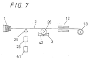
- Japanese Laid-Open Patent Publication No. 61-75869 published on April 18, 1986 discloses, as shown FIG. 7 of the accompanying drawings, a transfer roller 26 and a contacting/separating device 25 which are disposed along a yarn 2 from a bobbin 1.
- the contacting/separating device. 25 is controlled to move in a certain pattern by a controller 41 and a driver 23, the yarn 2 is selectively brought into and out of contact with the transfer roller 26.
- a liquid 42 composed of an adhesive and metal powder mixed therein and contained in a container 3 is therefore applied at random to the yarn 2 over a desired length.
- the yarn 2 with the liquid 42 applied thereto is thereafter dried by a heater 12 and wound around a tape-up bobbin 13.
- the yarn cannot be given a shiny metallic finish that would otherwise be possible with metallic foil, but only a dull metallic gloss. Therefore, any woven fabric of such yarn is of a low ornamental effect.
- Another problem is that the yarn is not flexible enough because of the resin layer of certain thickness on the surface of the yarn.
- a metallic foil may be wrapped around the surface of the yarn. Since, however, a metal foil has been hammered into a limit thickness, it is technically difficult to cover the yarn with the metallic foil because the metallic foil tends to shrink or curl around a region where it is gripped. It would be possible to wrap a yarn with a long ribbon-shaped foil and cut off gripped ends of the foil. However, larger foil is much more expensive than smaller foil, and it would not be easy to design a wrapping device and adjust the wrapping device according to the thickness of the yarn.
- metallic foil pieces 9 are scattered over and applied to a yarn 2 held under tension, and then the yarn 2 is twisted (see FIG. 1), or a swirling air stream is developed around the yarn (see FIG. 3), thereby wrapping the yarn 2 with the foil pieces 9 applied to the yarn 2.
- the yarn 2 to which the foil pieces 9 are to be applied is coated with an adhesive 4 in advance.
- the adhesive 4 should preferably be flexible enough even when it is in a solid state, so that the flexibility of the yarn 2 will not be impaired by the adhesive 4.
- the adhesive 4 may be of acrylic resin or urethane resin.
- the adhesive 4 is applied in as thin a layer as possible. If a woven cloth with a high design effect is to be made of the yarn 2, then the adhesive 4 should be applied to local regions of the yarn 2.
- the yarn 2 may be passed between a toothed transfer roller 6 (see FIG. 1) for transferring the adhesive 4 and a presser roller 7.
- a toothed transfer roller 6 see FIG. 1
- the yarn 2 may be moved into and out of contact with a transfer roller 26 (see FIG. 4) by a contacting/separating guide 25 that is vertically movable under the control of a computer.
- the yarn 2 to which the adhesive 4 is applied in its entirety or local regions is held under tension horizontally or obliquely, and fed in the direction in which it is tensioned while at the same time gold or silver foil pieces 9 are scattered over the yarn 2.
- the foil pieces 9 should preferably be in the form of small foil fragments of irregular shape.
- the foil pieces 9 are they fall are partially attached to the yarn 2 by the adhesive 4 applied to the yarn 2.
- the foil pieces 9 attached to the yarn 2 are then wrapped around the yarn 2 either due to inertia or air resistance when the yarn 2 is twisted, or by swirling air streams 19 (see FIGS. 2 and 3) developed in an air pipe 17 by inclined nozzles 18.
- the foil pieces 9 that have dropped onto the yarn 2 have portions attached to the yarn 2 by the adhesive 4, and the remaining portions of the foil pieces 9 are wrapped around the yarn 2 by the twisting of the yarn 2 or the swirling air flows.
- Those foil pieces 9 which are not attached to the yarn 2 return to hoppers 8, 27.
- a rotary hopper 27 shown in FIG. 7 is effective to generate swirling air streams around the yarn 2 with hopper blades 27c as they rotate.
- the foil pieces 9 are in the form of small foil fragments, no single foil piece will not be wrapped in layers around the yarn 2, and another foil will be attached to one foil piece that has been wrapped around the yarn 2.
- the metallic gloss imparted to the surface of the fancy yarn thus produced is highly shiny as it is given by the foil wrapped around the yarn.
- FIG. 1 shows, in side elevation, an apparatus according to a first embodiment of the present invention.
- a yarn 2 to be processed is supplied from a supply bobbin 1.
- the yarn 2 supplied from the supply bobbin 1 extends under tension from the supply bobbin 1 to a take-up bobbin 13.
- the apparatus has an adhesive container 3 that contains an adhesive 4 which may be of acrylic resin or urethane resin, and a pickup roller 5 that is partly immersed in the adhesive 4 in the adhesive container 3.
- the apparatus also includes a toothed transfer roller 6 for transferring the adhesive 4 to the yarn 2, a presser roller 7 for pressing the yarn 2 against the toothed transfer roller 6, a hopper 8 for scattering small gold or silver foil pieces 9 over the yarn 2, a tray 10 for receiving the foil pieces 9 dropped from the hopper 8, a yarn twister 11, and a heater 12.
- the take-up bobbin 13 can be rotated by an actuator.
- the yarn 2 supplied from the supply bobbin 1 is horizontally held under tension, fed in the direction in which it is held under tension, and then wound around the take-up bobbin 13.
- the yarn twister 11 is rotated repeatedly in one direction and then the other at constant timing for rotating the yarn 2 about its own axis in the directions indicated by the arrows 14.
- the toothed transfer roller 6 transfers the adhesive 4 from the adhesive container 3 to the yarn 2 when the top surface of each tooth thereof contacts the yarn 2.
- the adhesive 4 is thus applied to the yarn 2 at its discrete regions by the toothed transfer roller 6.
- the yarn 2 with the adhesive 4 applied is then guided below the hopper 8.
- the trapped foil pieces 9 are then wrapped around the yarn 2 as the yarn 2 is rotated reciprocally in the opposite directions.
- the yarn 2 wrapped with the foil pieces 9 is thereafter introduced into the heater 12, in which the adhesive 4 is hardened with heat to fix the wrapped foil pieces 9. Then, the yarn 2 is wound around the take-up bobbin 13.
- FIGS. 2 and 3 show an apparatus according to a second embodiment of the present invention.
- FIG. 2 shows the apparatus as a whole in side elevation
- FIG. 3 shows a wrapping section in perspective.
- a supply bobbin 1, a yarn 2, an adhesive container 3, an adhesive 4, a hopper 8, foil pieces 9, a tray 10, a heater 12, and a take-up bobbin 13 shown in FIGS. 2 and 3 are identical to those according to the first embodiment shown in FIG. 1.
- the apparatus according to the second embodiment includes a dipping roller 16 supported by a shaft in the adhesive container 3, a tunnel-shaped air pipe 17 surrounding the yarn 2 held under tension, and inclined nozzles 18 disposed in the air pipe 17.
- the inclined nozzles 18 eject air flows that serve as swirling air streams 19.
- the yarn 2 supplied from the supply bobbin 1 is dipped in the adhesive 4 in the adhesive container 3, so that the adhesive 4 is applied to the entire length of the yarn 2.
- the foil pieces 9 scattered from the hopper 8 are applied to the yarn 2 by the adhesive 4.
- the yarn 2 is introduced into the air pipe 17 in which the foil pieces 9 are wrapped around the yarn 2 by the swirling air streams 19 in the air pipe 17.
- FIGS. 4 through 6 illustrate an apparatus according to a third embodiment of the present invention.
- FIG. 4 shows the apparatus in side elevation
- FIG. 5 shows a rotary hopper in cross section
- FIG. 6 shows a yarn twister in perspective.
- a supply bobbin 1, a yarn 2, an adhesive container 3, an adhesive 4, foil pieces 9, a heater 12, and a take-up bobbin 13 shown in FIG. 4 are identical to those according to the first embodiment shown in FIG. 1.
- 4 through 6 has a yarn guide 21, a tensioner 22 for tensioning the yarn 2, a driver 23 energizable by a signal from a computer (not shown), a solenoid 24 energizable by the driver 23, a contacting/separating guide 25 that can be moved vertically by the solenoid 24, a transfer roller 26 partly immersed in the adhesive 4 in the adhesive container 3, a rotary hopper 27, suction nozzles 28, a yarn twister 29, guide rollers 30, 31, and a leasing roller 32.
- the contacting/separating guide 25 has a passage 25a through which the yarn 2 passes.
- the contacting/separating guide 25 When the contacting/separating guide 25 is elevated, it separates the yarn 2 from the transfer roller 26.
- the contacting/separating guide 25 When the contacting/separating guide 25 is lowered, it brings the yarn 2 into contact with the upper surface of the transfer roller 26.
- the contacting/separating guide 25 When the contacting/separating guide 25 is vertically moved in relation to the speed at which the yarn 2 is fed, the intervals at and lengths over which the adhesive 4 is applied to the yarn can be controlled.
- the rotary hopper 27 comprises rotary blades 27c disposed in a fixed cylinder 27b that has an opening 27a defined in an upper surface thereof and closable by a lid.
- the rotary blades 27c are fixed by a disk plate 27e to a hollow shaft 27d that is rotatable by a motor (not shown).
- the rotary blades 27c are rotatable closely to the inner surface of the fixed cylinder 27b.
- the yarn 2 with the adhesive 4 applied to local regions thereof passes through the center of rotation of the rotary hopper 27.
- the foil pieces 9 are introduced into the fixed cylinder 27b through the opening 27a, and scraped up from the bottom of the fixed cylinder 27b by the rotary blades 27c as they rotate, so that the foil pieces 9 are scattered over the yarn 2. Any foil pieces 9 that leak out of the fixed cylinder 27b through an inlet 27f and the end of the hollow shaft 27d are recovered by the suction nozzles 28.
- the yarn twister 29 comprises two belts 29a, 29b whose respective inner and outer surfaces are held against each other.
- the belts 29a, 29b are driven reciprocally in opposite directions by respective motors 29c, 29d.
- the yarn 2, which passes between the belts 29a, 29b, is rotated reciprocally in the directions indicated by the arrows 14 in FIG. 14. More precisely, the belts 29a, 29b move by small distances in opposite directions while they are being rotated reciprocally in the opposite directions, so that the entire surfaces of the belts 29a, 29b are put to use in twisting the yarn 2.
- the yarn 2 supplied from the supply bobbin 1 is selectively brought into contact with the transfer roller 26 upon vertical movement of the contacting/separating guide 25. Therefore, the regions of the yarn 2 where the adhesive 4 is to be applied can freely be controlled.
- the intervals between and lengths over which the adhesive 4 is applied to the yarn 2 can uniquely be determined depending on the design of a woven fabric that is to be made of the yarn 2.
- the contacting/separating guide 25 is thus vertically moved according to the design of such a woven fabric.
- the foil pieces 9 are attached to the adhesive-coated regions of the yarn 2, and wrapped around the yarn 2 by swirling air streams developed by the rotation of the rotary blades 27c and the reciprocating rotation of the yarn 2 in the yarn twister 29.
- the foil pieces 9 wrapped around the yarn 2 are fixed in position while passing through the heater 12, and securely pressed against the surface of the yarn 2 while passing between the belts 29a, 29b of the yarn twister 29.
- a yarn with an adhesive applied thereto is aerially held under tension and fed along, and foil pieces that are aerially scattered are attached to and wrapped around the yarn, thereby producing a fancy yarn.
- the gloss imparted to the surface of the fancy yarn is highly shiny as it is a metallic gloss given by the foil wrapped around the yarn.
- the method and apparatus according to the present invention allow a fancy yarn with a shiny metallic gloss to be manufactured simply and inexpensively, and also allow a thin yarn used to weave a thin fabric to be wrapped with a metallic foil as it is attached to the yarn.
- the yarn thus produced by the method and apparatus according to the present invention is effective to produce a woven fabric of highly ornamental effect.
Landscapes
- Engineering & Computer Science (AREA)
- Mechanical Engineering (AREA)
- Textile Engineering (AREA)
- Yarns And Mechanical Finishing Of Yarns Or Ropes (AREA)
- Woven Fabrics (AREA)
Abstract
Cette invention concerne un fil de fantaisie agencé de manière qu'une feuille d'or ou d'argent est enroulée autour de la surface du fil, un procédé et un appareil destinés à sa fabrication. Selon cette invention, un grand nombre de petits fragments de feuille de métal est enroulé autour et fixé à la surface du fil au moyen d'un adhésif. Ce fil peut être fabriqué en appliquant une matière adhésive au fil alors qu'il est alimenté à partir d'une bobine d'alimentation, en fixant des fragments de feuille de métal éparpillés dans l'air aux segments de fil qui sont déjà enrobés de matière adhésive alors que le fil est étiré dans l'air, en entortillant le fil auquel se sont accrochés les fragments de feuille de métal ou en enroulant ces fragments autour du fil au moyen d'un courant d'air tournoyant autour du fil, et finalement en fixant les fragments de feuille de métal dans cette position enroulée autour de la surface du fil en faisant sécher l'adhésif. selon cette invention, un fil de fantaisie ayant une surface joliment lustrée aux portions enrobées de métal peut être obtenu, et l'on peut en outre obtenir aisément un autre fil de fantaisie en roulant les feuilles de métal autour d'un fil très mince. Un excellent textile à grande valeur décorative peut aussi être obtenu lorsqu'on utilise le fil de fantaisie de cette invention comme chaînes de tissage ou comme trames.
Applications Claiming Priority (1)
| Application Number | Priority Date | Filing Date | Title |
|---|---|---|---|
| PCT/JP1990/000271 WO1991013196A1 (fr) | 1990-03-01 | 1990-03-01 | Fil de fantaisie enrobe d'une feuille de metal, procede de fabrication et appareil pour fabriquer ledit fil |
Publications (2)
| Publication Number | Publication Date |
|---|---|
| EP0474864A1 true EP0474864A1 (fr) | 1992-03-18 |
| EP0474864A4 EP0474864A4 (en) | 1992-08-26 |
Family
ID=13986381
Family Applications (1)
| Application Number | Title | Priority Date | Filing Date |
|---|---|---|---|
| EP19900903939 Withdrawn EP0474864A4 (en) | 1990-03-01 | 1990-03-01 | Metal-foiled fancy yarn, method of its production and apparatus therefor |
Country Status (3)
| Country | Link |
|---|---|
| US (1) | US5201169A (fr) |
| EP (1) | EP0474864A4 (fr) |
| WO (1) | WO1991013196A1 (fr) |
Cited By (1)
| Publication number | Priority date | Publication date | Assignee | Title |
|---|---|---|---|---|
| US20120202399A1 (en) * | 2011-02-04 | 2012-08-09 | Michael Rubin | Foil lame' fabrics and methods of making foil lame' fabrics |
Families Citing this family (5)
| Publication number | Priority date | Publication date | Assignee | Title |
|---|---|---|---|---|
| US6602544B2 (en) * | 2001-08-29 | 2003-08-05 | Veronica Piselli | Mineral compound composite textile material and method of manufacturing |
| US7069714B2 (en) * | 2003-03-20 | 2006-07-04 | Daniele De Boni | Metal covered composite yarn, particularly for ornamental purposes |
| US7886515B2 (en) * | 2008-07-02 | 2011-02-15 | AG Technologies, Inc. | Process for manufacturing yarn made from a blend of fibers of cotton, nylon and silver |
| US7882688B2 (en) * | 2008-07-02 | 2011-02-08 | AG Technologies, Inc. | Process for manufacturing yarn made from a blend of polyester fibers and silver fibers |
| US10041208B1 (en) | 2015-09-28 | 2018-08-07 | Leonid Batekhin | Textile fabrication system |
Family Cites Families (11)
| Publication number | Priority date | Publication date | Assignee | Title |
|---|---|---|---|---|
| US2007183A (en) * | 1930-10-02 | 1935-07-09 | Celanese Corp | Textile materials and the production thereof |
| US2058783A (en) * | 1935-10-05 | 1936-10-27 | Franke Edward Philip | Decorative cord |
| US2230271A (en) * | 1937-05-22 | 1941-02-04 | Owens Corning Fiberglass Corp | Method of producing combined asbestos and glass fiber yarns |
| FR1143690A (fr) * | 1955-12-07 | 1957-10-03 | Fil et son procédé de fabrication | |
| GB922692A (en) * | 1962-01-30 | 1963-04-03 | Metal Film Company Inc | Improvements in or relating to lame fabrics and yarns therefor |
| US3361616A (en) * | 1963-12-20 | 1968-01-02 | Walter G. Scharf | Flecked metallized yarn |
| CA1046728A (fr) * | 1975-11-03 | 1979-01-23 | Adrien R. Gauthier | Dispositif de fabrication de rubans conducteurs |
| DE3408795A1 (de) * | 1984-03-10 | 1985-09-12 | Haug GmbH & Co. KG, 7022 Leinfelden-Echterdingen | Verfahren und vorrichtung zum fortlaufenden herstellen elektrischer rund- oder flachbandkabel |
| JPS6175869A (ja) * | 1984-09-14 | 1986-04-18 | 山梨県 | 絣染金属加工糸の製造方法 |
| GB2214937B (en) * | 1988-02-09 | 1991-12-11 | Ppg Glass Fibres Limited | Improvements in and relating to glass fibre products |
| JPH0660453B2 (ja) * | 1988-08-24 | 1994-08-10 | 徹 宮下 | 金属箔意匠糸の製造方法 |
-
1990
- 1990-03-01 EP EP19900903939 patent/EP0474864A4/en not_active Withdrawn
- 1990-03-01 WO PCT/JP1990/000271 patent/WO1991013196A1/fr not_active Ceased
- 1990-03-01 US US07/773,919 patent/US5201169A/en not_active Expired - Fee Related
Cited By (1)
| Publication number | Priority date | Publication date | Assignee | Title |
|---|---|---|---|---|
| US20120202399A1 (en) * | 2011-02-04 | 2012-08-09 | Michael Rubin | Foil lame' fabrics and methods of making foil lame' fabrics |
Also Published As
| Publication number | Publication date |
|---|---|
| WO1991013196A1 (fr) | 1991-09-05 |
| US5201169A (en) | 1993-04-13 |
| EP0474864A4 (en) | 1992-08-26 |
Similar Documents
| Publication | Publication Date | Title |
|---|---|---|
| US5099554A (en) | Method and apparatus for fabric production | |
| PL132018B1 (en) | Method of manufacture of non-twisted yarn from at least two separate skeins of thermoplastic skein material | |
| US3575217A (en) | Device for storing weft material in weaving machines | |
| US5201169A (en) | Metallic-foil-covered fancy yarn and method of fan apparatus for manufacturing same | |
| US3791132A (en) | Process for sizing textile fibres | |
| US4564992A (en) | Method for producing helix structures for use in forming helix belts | |
| US20070056607A1 (en) | Process and apparatus for cleaning wires or the outer surface of a tube | |
| US4578141A (en) | Weft forming apparatus | |
| US20070095043A1 (en) | Machine for yarn cabling/twisting and continuous setting | |
| JPH0759771B2 (ja) | フロツク加工されたフアイバ−或いは糸状材料を造るための方法およびこの方法を実施するための装置およびこの方法とこの装置で造られるフロツク加工されたフアイバ−或いは糸状材料 | |
| US3659439A (en) | Yarn treatment apparatus | |
| US4191010A (en) | Process and device for producing fancy yarn | |
| JPWO1991013196A1 (ja) | 金属箔意匠糸、その製造方法及び製造装置 | |
| US4355499A (en) | Fabrics having salt-and-pepper patterns and crimped filament yarns for producing the same | |
| DE2928383C2 (de) | Vorrichtung zum Spannungsausgleich des Schußfadens einer Nadelbandwebmaschine | |
| US3885277A (en) | Apparatus for sizing textile fibres | |
| US4682637A (en) | Linear weaving machine | |
| JPH0261123A (ja) | 金属箔意匠糸の製造方法 | |
| CN1030000C (zh) | 弹性复合丝及其制造方法 | |
| US1492316A (en) | Thread conditioning and manipulating device | |
| KR890004307Y1 (ko) | 표면형 파스너의 루우프 성형직기용 맨드렐 | |
| JPS5928054Y2 (ja) | 金銀加工糸 | |
| JPS6249388B2 (fr) | ||
| GB2073792A (en) | Raised Yarn | |
| US4425691A (en) | Fabric forming process |
Legal Events
| Date | Code | Title | Description |
|---|---|---|---|
| PUAI | Public reference made under article 153(3) epc to a published international application that has entered the european phase |
Free format text: ORIGINAL CODE: 0009012 |
|
| 17P | Request for examination filed |
Effective date: 19911118 |
|
| AK | Designated contracting states |
Kind code of ref document: A1 Designated state(s): DE FR GB IT |
|
| A4 | Supplementary search report drawn up and despatched |
Effective date: 19920709 |
|
| AK | Designated contracting states |
Kind code of ref document: A4 Designated state(s): DE FR GB IT |
|
| STAA | Information on the status of an ep patent application or granted ep patent |
Free format text: STATUS: THE APPLICATION HAS BEEN WITHDRAWN |
|
| 18W | Application withdrawn |
Withdrawal date: 19930302 |