EP0474943A2 - Einstellbarer Widerstand - Google Patents
Einstellbarer Widerstand Download PDFInfo
- Publication number
- EP0474943A2 EP0474943A2 EP90314118A EP90314118A EP0474943A2 EP 0474943 A2 EP0474943 A2 EP 0474943A2 EP 90314118 A EP90314118 A EP 90314118A EP 90314118 A EP90314118 A EP 90314118A EP 0474943 A2 EP0474943 A2 EP 0474943A2
- Authority
- EP
- European Patent Office
- Prior art keywords
- resistor
- turn
- pieces
- push button
- piece
- Prior art date
- Legal status (The legal status is an assumption and is not a legal conclusion. Google has not performed a legal analysis and makes no representation as to the accuracy of the status listed.)
- Granted
Links
Images


Classifications
-
- H—ELECTRICITY
- H01—ELECTRIC ELEMENTS
- H01C—RESISTORS
- H01C10/00—Adjustable resistors
- H01C10/10—Adjustable resistors adjustable by mechanical pressure or force
- H01C10/12—Adjustable resistors adjustable by mechanical pressure or force by changing surface pressure between resistive masses or resistive and conductive masses, e.g. pile type
-
- H—ELECTRICITY
- H01—ELECTRIC ELEMENTS
- H01C—RESISTORS
- H01C10/00—Adjustable resistors
- H01C10/06—Adjustable resistors adjustable by short-circuiting different amounts of the resistive element
Definitions
- the invention relates to a variable resistor device, more particularly to a device wherein resistance is varied by pressing a push button.
- Variable resistor devices are known in the art. Examples of such devices include slide-wire potentiometers and dial resistors.
- the objective of the present invention is to provide a novel variable resistor device wherein the resistance is varied by pressing a push button.
- Another objective of the present invention is to provide a push button variable resistor device which can be incorporated in a key of a computer keyboard or an electronic organ keyboard.
- a push button variable resistor device includes a hollow push button seat member confining a receiving space, and at least one resistor piece fixed inside the seat member.
- the resistor piece has a contact portion and two leg portions projecting outward through the base of the seat member.
- a spiral spring resistor is disposed inside the receiving space of the seat member above the resistor piece.
- the spring resistor has a plurality of concentric turns of varying diameters.
- a push button is slidably fitted through a button opening of the seat member.
- the spring resistor has a topmost turn cooperatively associated with the push button.
- the push button compresses the spring resistor, forcing its concentric turns to contact the resistor piece one after the other.
- the contact area between the spring resistor and the resistor piece varies according to the degree of depression of the push button. This makes possible the objective of varying the resistance with the use of a push button.
- the present invention can be applied in a keyboard which includes a plate member having a plurality of openings, a base plate fastened to the plate member, a circuit board fixed between the plate member and the base plate, and a plurality of cavity members provided between the plate member and the base plate and accessible through the openings.
- a spiral spring resistor with a plurality of concentric turns of decreasing diameter is disposed inside each of the cavity members.
- a predetermined number of resistor pieces is disposed on the circuit board below each spring resistor. Each resistor piece has a pair of leg portions attached to the circuit board.
- the keyboard further includes a plurality of push buttons cooperatively associated with the spring resistors.
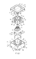
- variable resistor device according to the present invention is shown to comprise a seat casing 1, a seat cover 2, a predetermined number of resistor pieces 3, a spiral spring resistor 4, and a push button 5.
- the seat casing 1 has four square walls 11 and a square base 12 that confine a receiving space 10.
- each of the square walls 11 has a pair of inwardly projecting parallel retaining ribs 13.
- Each of the retaining ribs 13 are disposed equally distant from the center of each square wall 11 and extend from the top end of the square wall 11 to the square base 12.
- Each pair of vertical ribs 13 defines a groove 14.
- the square base 12 has an opening 15 directly beneath each groove 14.
- a pair of transverse raised ribs 16 extend from each pair of vertical ribs 13 at the square base 12.
- Each pair of transverse raised ribs 16 define a second groove 160.
- an outwardly protruding hook 17 projects from each of the two upper corners at the outer face of each square wall 11.
- a pair of spaced rail receiving hooks 18 projects from the lower edge of each square wall 11.
- the seat cover 2 has a square top wall 22 with a central square button opening 23.
- Four flanges 20 extend downward from the four outer edges of the top wall 22.
- Four engaging notches 21 are formed in the flanges 20 adjacent to four corners of the top wall 22.
- the seat cover 2 further includes four support posts 24 which extend downward from the top wall 22.
- each of the resistor pieces 3 can be made from materials of different resistivity.
- the first preferred embodiment has two resistor pieces 3.
- Each resistor piece 3 is formed as a strip with a contact portion 30 and a pair of downwardly extending leg portions 32.
- the resistor pieces 3 and the spiral spring resistor 4 preferably conform to one of the following combinations:
- the spiral spring resistor 4 comprises a series of concentric turns of increasing diameter: the topmost turn 41 of the spiral spring resistor 4 has the smallest diameter while the bottom endmost turn 42 of the spiral spring resistor 4 has the widest diameter. Applying a compressing force on the topmost turn 41 of the spiral spring resistor 4 causes the other turns of the spiral spring resistor 4 to contact the resistor pieces 3. The number of turns of the spiral spring resistor 4 which contact the resistor pieces 3 depends upon the magnitude of the pressing force applied.
- the push button 5 has four square walls 53 which form a square box that is to be fitted into the button opening 23 of the seat cover 2.
- the topmost turn 41 of the spiral spring resistor 4 surrounds a downward projection 51 that protrudes from a bottom wall of the push button 5.
- the push button 5 has inner wall portions 52 which confine a cross-shaped receiving space 50.
- the inner wall portions 52 and the square walls 53 of the push button 5 confine a clearance 54.
- a pair of transverse outward projections 55 extends from the two lower corners of each square wall 53.
- the outward projections 55 slidably contact the square walls 11 of the seat casing 1.
- Each square wall 53 has a pair of spaced vertical grooves 531 to form a resilient piece 56.
- Each resilient piece 56 has a horizontal outward projection 57 that is substantially triangular in shape. When a pressing force is applied to the horizontal projection 57, the resilient piece 56 is forced to lean into the clearance 54. Movement of the push button 5 relative to the seat cover 2 would cause the peripheral edges confining the button opening 23 to contact the horizontal projection 57 and thus cause the application of a pressing force thereat.
- a bent support rail 1 a is longitudinally disposed between each pair of receiving hooks 18.
- the support rail 1 a provides stability to the variable resistor device when a pressing force is applied on the push button 5.
- FIGs 8 and 8A illustrate the operation of the preferred embodiment.
- the leg portions 32 of the resistor pieces 3 are to be electrically connected to the control circuit of a computer keyboard (not shown).
- a key cap 6 of a conventional computer key is connected to the push button 5 at the cross-shaped receiving space 50.
- the spiral spring resistor 4 starts to compress and its second bottom endmost turn 42a contacts the resistor pieces 3.
- Current starts to flow through the resistor pieces 3 to signify a closed circuit condition.
- the magnitude of the pressing force applied is increased, the succeeding turns consecutively contact the resistor pieces 3.
- the seat cover 2 comes into contact with the horizontal projection 57 of the push button 5, thus forcing the resilient piece 56 of the push button 5 into the clearance 54.
- the peripheral edges of the seat cover 2 which define the button opening 23 prevent the spiral spring resistor 4 from expanding back into its uncompressed state when the horizontal projection 57 is disposed below the top wall 22 of the seat cover 2.
- the key cap 6 is pulled upward to move the horizontal projection 57 past the top wall 22 to permit the spring 4 to return to its uncompressed state.
- Figure 8B illustrates an alternative arrangement of the spiral spring resistor 4 and the resistor pieces 3.
- the bottom endmost turn 42 is coated with an insulating material and is in constant contact with the resistor pieces 3.
- Figure 9 is a second preferred embodiment of a pair of resistor pieces according to the present invention.
- the resistor pieces 3a and 3b each have a pair of downwardly extending leg portions 34 which extend through the square base 12 through the openings 15.
- the resistor pieces 3a and 3b each have a flat contact portion 30' for the spiral spring resistor 4.
- the resistor piece 3a is disposed transverse to and on top of the resistor piece 3b.
- the resistor piece 3a has an upwardly projecting bent portion 3c to prevent the resistor piece 3a from coming into contact with the resistor piece 3b.
- Figure 10 is another preferred embodiment of a resistor piece according to the present invention.
- the resistor piece 3' comprises an annular contact portion 3d with a central circular opening 3e and a pair of downwardly extending leg portions 3f.
- the pair of downwardly extending leg portions 3f extend through holes B1 of a seat member B.
- spiral spring resistors 4' may be used: (a) a spiral spring resistor 4a (not shown) comprising a series of turns of decreasing diameter with the topmost turn having the widest diameter and the bottom endmost turn having the smallest diameter; or (b) a spiral spring resistor 4b (shown in Figures 10A and 10B) comprising a series of turns with the centermost turn having the widest diameter and the topmost and bottom endmost turns having the smallest diameters.
- the topmost turn of the spiral spring resistor 4' is in contact with a push button piece A.
- the bottom endmost turn of the spiral spring resistor 4' is disposed in the central circular opening 3e and extends outward through the seat member B.
- the spring 4' is not in contact with the resistor piece 3' when it is in an uncompressed state.
- the spring 4' starts to compress, it contacts the resistor piece 3' to vary the resistance measured between one of the leg portions 3f of the resistor piece 3' and the bottom endmost turn of the spring 4'. As the contact area between the spring 4' and the resistor piece 3' increases, the resistance decreases.
- FIG 11 is an illustration of a keyboard incorporating the variable resistor device according to the present invention.
- a base plate 7A is fastened to the plate member 7.
- a plurality of cavity members 70 is provided between the plate member 7 and the base plate 7A. The cavity members 70 can be accessed through the openings 700.
- a predetermined number of inwardly protruding vertical rib pairs 71 project from each cavity member 70. Each vertical rib pair 71 confines a groove 72 similar to the groove 14 of the seat casing 1 (Refer to Figure 1).
- the base plate 7A has a plurality of screw holes 70A aligned with screw sockets 73 of the plate member 7 to receive screws for fastening the plate member 7 and the base plate 7A together.
- a printed circuit board 8 is fixed between the plate member 7 and the base plate 7A.
- a spiral spring resistor 4' is disposed inside each cavity member 70 and comprises a plurality of concentric turns including a topmost turn 41' and a bottom endmost turn 42'.
- a predetermined number of resistor pieces 3' is provided on the circuit board 8 below each of the spiral spring resistors 4'.
- Each resistor piece 3' has leg portions attached to the circuit board 8. The bottom endmost turn 42' is electrically isolated from the resistor pieces 3'.
- the topmost turn 41' of the spiral spring resistor 4' is disposed around a downward projection 93 of one of the push button members 9.
- a key cap 95 is attached to each push button member 9.
- Each of the push button members 9 has flange sections projecting into one of the grooves 72 of each cavity member 70 to guide the movement of the push button members 9 relative to the cavity members 70.
Landscapes
- Engineering & Computer Science (AREA)
- Microelectronics & Electronic Packaging (AREA)
- Push-Button Switches (AREA)
- Adjustable Resistors (AREA)
- Networks Using Active Elements (AREA)
- Stringed Musical Instruments (AREA)
- Electrical Discharge Machining, Electrochemical Machining, And Combined Machining (AREA)
- Amplifiers (AREA)
- Oscillators With Electromechanical Resonators (AREA)
- Control Of Electric Motors In General (AREA)
Applications Claiming Priority (2)
| Application Number | Priority Date | Filing Date | Title |
|---|---|---|---|
| US580596 | 1984-02-16 | ||
| US07/580,596 US5059939A (en) | 1990-09-11 | 1990-09-11 | Variable resistor device |
Publications (3)
| Publication Number | Publication Date |
|---|---|
| EP0474943A2 true EP0474943A2 (de) | 1992-03-18 |
| EP0474943A3 EP0474943A3 (en) | 1993-01-13 |
| EP0474943B1 EP0474943B1 (de) | 1995-04-12 |
Family
ID=24321730
Family Applications (1)
| Application Number | Title | Priority Date | Filing Date |
|---|---|---|---|
| EP90314118A Expired - Lifetime EP0474943B1 (de) | 1990-09-11 | 1990-12-21 | Einstellbarer Widerstand |
Country Status (5)
| Country | Link |
|---|---|
| US (1) | US5059939A (de) |
| EP (1) | EP0474943B1 (de) |
| AT (1) | ATE121215T1 (de) |
| DE (1) | DE69018632T2 (de) |
| ES (1) | ES2073544T3 (de) |
Cited By (1)
| Publication number | Priority date | Publication date | Assignee | Title |
|---|---|---|---|---|
| EP3671772A1 (de) * | 2018-12-21 | 2020-06-24 | Vestel Elektronik Sanayi ve Ticaret A.S. | Steuerungssystem mit drehknopf |
Families Citing this family (6)
| Publication number | Priority date | Publication date | Assignee | Title |
|---|---|---|---|---|
| US6262712B1 (en) * | 1997-04-24 | 2001-07-17 | Microsoft Corporation | Handle sensor with fade-in |
| US7133033B1 (en) * | 1999-12-02 | 2006-11-07 | Advanced Input Devices Uk Limited | Actuator for a switch |
| CN105556988B (zh) * | 2013-09-18 | 2019-03-22 | 领先仿生公司 | 助听装置和与其一起使用的用户界面 |
| US9435680B2 (en) | 2014-03-24 | 2016-09-06 | Deringer-Ney, Inc. | Apparatuses and methods for fuel level sensing |
| US9488515B2 (en) | 2014-03-24 | 2016-11-08 | Deringer-Ney, Inc. | Apparatuses and methods for fuel level sensing |
| CN113936875B (zh) * | 2021-10-18 | 2022-06-07 | 浙江玖维电子科技有限公司 | 一种贴片电阻 |
Family Cites Families (8)
| Publication number | Priority date | Publication date | Assignee | Title |
|---|---|---|---|---|
| US260623A (en) * | 1882-07-04 | starr | ||
| US488121A (en) * | 1892-12-13 | hougxxton g | ||
| US3134045A (en) * | 1960-12-01 | 1964-05-19 | Wells Gardner Electronics | Combined picture width and high voltage control circuit for television receiver |
| DE1763177A1 (de) * | 1968-04-17 | 1971-09-23 | Steinbock Gmbh | Stufenlos regelbarer Widerstand |
| DE2041850A1 (de) * | 1970-08-22 | 1972-02-24 | Bosch Gmbh Robert | Elektrischer Stellwiderstand |
| US4257305A (en) * | 1977-12-23 | 1981-03-24 | Arp Instruments, Inc. | Pressure sensitive controller for electronic musical instruments |
| US4430595A (en) * | 1981-07-29 | 1984-02-07 | Toko Kabushiki Kaisha | Piezo-electric push button switch |
| JPS63202809A (ja) * | 1987-02-19 | 1988-08-22 | 松下電器産業株式会社 | 携帯機用キ−ボ−ド |
-
1990
- 1990-09-11 US US07/580,596 patent/US5059939A/en not_active Expired - Fee Related
- 1990-12-21 ES ES90314118T patent/ES2073544T3/es not_active Expired - Lifetime
- 1990-12-21 EP EP90314118A patent/EP0474943B1/de not_active Expired - Lifetime
- 1990-12-21 AT AT90314118T patent/ATE121215T1/de not_active IP Right Cessation
- 1990-12-21 DE DE69018632T patent/DE69018632T2/de not_active Expired - Fee Related
Cited By (1)
| Publication number | Priority date | Publication date | Assignee | Title |
|---|---|---|---|---|
| EP3671772A1 (de) * | 2018-12-21 | 2020-06-24 | Vestel Elektronik Sanayi ve Ticaret A.S. | Steuerungssystem mit drehknopf |
Also Published As
| Publication number | Publication date |
|---|---|
| DE69018632D1 (de) | 1995-05-18 |
| EP0474943B1 (de) | 1995-04-12 |
| ES2073544T3 (es) | 1995-08-16 |
| EP0474943A3 (en) | 1993-01-13 |
| DE69018632T2 (de) | 1995-10-12 |
| ATE121215T1 (de) | 1995-04-15 |
| US5059939A (en) | 1991-10-22 |
Similar Documents
| Publication | Publication Date | Title |
|---|---|---|
| US3509296A (en) | Resilient variable-conductivity circuit controlling means | |
| USRE30435E (en) | Keyboard switch arrangement and key switch useable therein | |
| US5668358A (en) | Reconfigurable keyboard | |
| US4385218A (en) | Electric switch | |
| US5386091A (en) | Low profile keyswitch | |
| US4072840A (en) | Removable keyboard switch | |
| EP0474943B1 (de) | Einstellbarer Widerstand | |
| JPH09120748A (ja) | キー組立体 | |
| US4736076A (en) | Capacitance switching device for keyboard | |
| US4943694A (en) | Push-button cover assembly | |
| US6133539A (en) | Key switch | |
| US4325102A (en) | Variable capacitor for use in a keyboard | |
| US7102088B2 (en) | Multi-direction switch | |
| US4972056A (en) | Keyswitch | |
| US3671915A (en) | Sliding type variable resistor | |
| US4453052A (en) | Adjustable pressure switch | |
| US4466046A (en) | Capacitive keyboard switch | |
| CA1051194A (en) | Electronic experimenting kit | |
| JP4278529B2 (ja) | 多方向入力装置 | |
| JPH0357114A (ja) | 押釦スイッチ | |
| US4482932A (en) | Keyboard switch | |
| US2929893A (en) | Electric mat switch | |
| JPS6023869Y2 (ja) | 押釦スイツチ | |
| CN221177686U (zh) | 触摸按键装置 | |
| KR930009235B1 (ko) | 푸시 버튼 스위치 |
Legal Events
| Date | Code | Title | Description |
|---|---|---|---|
| PUAI | Public reference made under article 153(3) epc to a published international application that has entered the european phase |
Free format text: ORIGINAL CODE: 0009012 |
|
| AK | Designated contracting states |
Kind code of ref document: A2 Designated state(s): AT BE CH DE DK ES FR GB GR IT LI LU NL SE |
|
| PUAL | Search report despatched |
Free format text: ORIGINAL CODE: 0009013 |
|
| AK | Designated contracting states |
Kind code of ref document: A3 Designated state(s): AT BE CH DE DK ES FR GB GR IT LI LU NL SE |
|
| 17P | Request for examination filed |
Effective date: 19930707 |
|
| 17Q | First examination report despatched |
Effective date: 19940422 |
|
| GRAA | (expected) grant |
Free format text: ORIGINAL CODE: 0009210 |
|
| AK | Designated contracting states |
Kind code of ref document: B1 Designated state(s): AT BE CH DE DK ES FR GB GR IT LI LU NL SE |
|
| PG25 | Lapsed in a contracting state [announced via postgrant information from national office to epo] |
Ref country code: NL Free format text: LAPSE BECAUSE OF NON-PAYMENT OF DUE FEES Effective date: 19950412 Ref country code: LI Effective date: 19950412 Ref country code: GR Free format text: LAPSE BECAUSE OF FAILURE TO SUBMIT A TRANSLATION OF THE DESCRIPTION OR TO PAY THE FEE WITHIN THE PRESCRIBED TIME-LIMIT Effective date: 19950412 Ref country code: DK Effective date: 19950412 Ref country code: CH Effective date: 19950412 Ref country code: BE Effective date: 19950412 Ref country code: AT Effective date: 19950412 |
|
| REF | Corresponds to: |
Ref document number: 121215 Country of ref document: AT Date of ref document: 19950415 Kind code of ref document: T |
|
| ITF | It: translation for a ep patent filed | ||
| REF | Corresponds to: |
Ref document number: 69018632 Country of ref document: DE Date of ref document: 19950518 |
|
| ET | Fr: translation filed | ||
| PG25 | Lapsed in a contracting state [announced via postgrant information from national office to epo] |
Ref country code: SE Effective date: 19950712 |
|
| REG | Reference to a national code |
Ref country code: CH Ref legal event code: PL |
|
| REG | Reference to a national code |
Ref country code: ES Ref legal event code: FG2A Ref document number: 2073544 Country of ref document: ES Kind code of ref document: T3 |
|
| NLV1 | Nl: lapsed or annulled due to failure to fulfill the requirements of art. 29p and 29m of the patents act | ||
| PG25 | Lapsed in a contracting state [announced via postgrant information from national office to epo] |
Ref country code: LU Free format text: LAPSE BECAUSE OF NON-PAYMENT OF DUE FEES Effective date: 19951231 |
|
| PLBE | No opposition filed within time limit |
Free format text: ORIGINAL CODE: 0009261 |
|
| STAA | Information on the status of an ep patent application or granted ep patent |
Free format text: STATUS: NO OPPOSITION FILED WITHIN TIME LIMIT |
|
| 26N | No opposition filed | ||
| PGFP | Annual fee paid to national office [announced via postgrant information from national office to epo] |
Ref country code: GB Payment date: 19971210 Year of fee payment: 8 |
|
| PGFP | Annual fee paid to national office [announced via postgrant information from national office to epo] |
Ref country code: FR Payment date: 19971224 Year of fee payment: 8 |
|
| PGFP | Annual fee paid to national office [announced via postgrant information from national office to epo] |
Ref country code: ES Payment date: 19971231 Year of fee payment: 8 |
|
| PGFP | Annual fee paid to national office [announced via postgrant information from national office to epo] |
Ref country code: DE Payment date: 19980112 Year of fee payment: 8 |
|
| PG25 | Lapsed in a contracting state [announced via postgrant information from national office to epo] |
Ref country code: GB Free format text: LAPSE BECAUSE OF NON-PAYMENT OF DUE FEES Effective date: 19981221 |
|
| PG25 | Lapsed in a contracting state [announced via postgrant information from national office to epo] |
Ref country code: ES Free format text: LAPSE BECAUSE OF THE APPLICANT RENOUNCES Effective date: 19981222 |
|
| GBPC | Gb: european patent ceased through non-payment of renewal fee |
Effective date: 19981221 |
|
| PG25 | Lapsed in a contracting state [announced via postgrant information from national office to epo] |
Ref country code: FR Free format text: LAPSE BECAUSE OF NON-PAYMENT OF DUE FEES Effective date: 19990831 |
|
| REG | Reference to a national code |
Ref country code: FR Ref legal event code: ST |
|
| PG25 | Lapsed in a contracting state [announced via postgrant information from national office to epo] |
Ref country code: DE Free format text: LAPSE BECAUSE OF NON-PAYMENT OF DUE FEES Effective date: 19991001 |
|
| REG | Reference to a national code |
Ref country code: ES Ref legal event code: FD2A Effective date: 20010402 |
|
| PG25 | Lapsed in a contracting state [announced via postgrant information from national office to epo] |
Ref country code: IT Free format text: LAPSE BECAUSE OF NON-PAYMENT OF DUE FEES;WARNING: LAPSES OF ITALIAN PATENTS WITH EFFECTIVE DATE BEFORE 2007 MAY HAVE OCCURRED AT ANY TIME BEFORE 2007. THE CORRECT EFFECTIVE DATE MAY BE DIFFERENT FROM THE ONE RECORDED. Effective date: 20051221 |