EP0475008B1 - Procédé et dispositif de commande de la force appliquée au bras de support pour électrode d'un four à arc - Google Patents
Procédé et dispositif de commande de la force appliquée au bras de support pour électrode d'un four à arc Download PDFInfo
- Publication number
- EP0475008B1 EP0475008B1 EP91111325A EP91111325A EP0475008B1 EP 0475008 B1 EP0475008 B1 EP 0475008B1 EP 91111325 A EP91111325 A EP 91111325A EP 91111325 A EP91111325 A EP 91111325A EP 0475008 B1 EP0475008 B1 EP 0475008B1
- Authority
- EP
- European Patent Office
- Prior art keywords
- pressure
- electrode
- electrodes
- processor system
- operational cylinder
- Prior art date
- Legal status (The legal status is an assumption and is not a legal conclusion. Google has not performed a legal analysis and makes no representation as to the accuracy of the status listed.)
- Expired - Lifetime
Links
- 238000000034 method Methods 0.000 title claims abstract description 14
- 238000010891 electric arc Methods 0.000 title claims abstract description 13
- 230000003068 static effect Effects 0.000 claims abstract description 20
- 239000012530 fluid Substances 0.000 claims abstract description 7
- 238000005259 measurement Methods 0.000 claims description 4
- 230000002596 correlated effect Effects 0.000 claims description 2
- 238000003723 Smelting Methods 0.000 description 7
- 238000012544 monitoring process Methods 0.000 description 4
- 239000011810 insulating material Substances 0.000 description 2
- 230000001276 controlling effect Effects 0.000 description 1
- 230000000875 corresponding effect Effects 0.000 description 1
- 230000001419 dependent effect Effects 0.000 description 1
- 230000001627 detrimental effect Effects 0.000 description 1
- 238000010586 diagram Methods 0.000 description 1
- 238000010304 firing Methods 0.000 description 1
- 239000000463 material Substances 0.000 description 1
- 239000012811 non-conductive material Substances 0.000 description 1
- 230000000284 resting effect Effects 0.000 description 1
Images
Classifications
-
- H—ELECTRICITY
- H05—ELECTRIC TECHNIQUES NOT OTHERWISE PROVIDED FOR
- H05B—ELECTRIC HEATING; ELECTRIC LIGHT SOURCES NOT OTHERWISE PROVIDED FOR; CIRCUIT ARRANGEMENTS FOR ELECTRIC LIGHT SOURCES, IN GENERAL
- H05B7/00—Heating by electric discharge
- H05B7/02—Details
- H05B7/144—Power supplies specially adapted for heating by electric discharge; Automatic control of power, e.g. by positioning of electrodes
- H05B7/148—Automatic control of power
- H05B7/156—Automatic control of power by hydraulic or pneumatic means for positioning of electrodes
-
- Y—GENERAL TAGGING OF NEW TECHNOLOGICAL DEVELOPMENTS; GENERAL TAGGING OF CROSS-SECTIONAL TECHNOLOGIES SPANNING OVER SEVERAL SECTIONS OF THE IPC; TECHNICAL SUBJECTS COVERED BY FORMER USPC CROSS-REFERENCE ART COLLECTIONS [XRACs] AND DIGESTS
- Y02—TECHNOLOGIES OR APPLICATIONS FOR MITIGATION OR ADAPTATION AGAINST CLIMATE CHANGE
- Y02P—CLIMATE CHANGE MITIGATION TECHNOLOGIES IN THE PRODUCTION OR PROCESSING OF GOODS
- Y02P10/00—Technologies related to metal processing
- Y02P10/25—Process efficiency
Definitions
- This invention concerns a method and relative device to control the force applied to the electrode-bearing arms of an electric arc furnace.
- the invention concerns a method and device suitable to control constantly the force applied to the electrode-bearing arms of an electric arc furnace, the force being suitable to lift and position the electrode in a required manner in a vertical direction.
- Document DE-A-2.312.603 (and therewith also FR-A-2.402.993) is known and concerns a device to prevent breakage of electrodes in electric furnaces having electrical, electrohydraulic or electropneumatic regulation, in particular for smelting of scrap; this device consists of an operational cylinder actuated by a fluid under pressure so as to lift and lower the electrodes, the control means of the cylinder being adjustable by means of an electrical commutator device which responds in the event of excursions of the current of the electrodes from the nominal value.
- a pressure switch is connected to the circuit under pressure of the operational cylinder and transmits by means of its switch to the control means a signal to lift the electrodes in the event of a drop of pressure in the operational cylinder when the electrodes contact non-conductive materials and when a given response pressure is reached in the operational cylinder.
- the circuit is also connected to a switch which, upon reduction of pressure in the operational cylinder, interrupts simultaneously the current fed to the electrical regulation circuit and, upon attainment of the response pressure, restarts the current, which in turn transmits a signal for lowering of the electrodes.
- the circuit cannot monitor constantly and continuously by means of the pressure switch the variable value of the static pressure in the cylinder and therefore can perform neither an automatic control of the value of wear of the electrodes nor the memorisation of the value of the weight of the arm at every speedy descent of the electrodes for the beginning of smelting, nor regulation in a closed circuit with a servovalve having a speedy response for control of the electrodes by means of a pressure control; the circuit is not even able to carry out automatic regulation with an electronic system to regulate the electrodes so as to prevent any short circuits at the electic arc during smelting, nor can it prevent automatically an accidental breakage of the electrodes.
- the known document employs a pressure switch, which of necessity has to be set with a given minus step as compared to the minimum actual value; and therefore when the pressure switch senses the pressure of actuation, there is the danger that the electrode may be already broken since this step of interval may be too great for the typical requirements of the electrode.
- the prior art document DE-A-3.242.934 provides for measurement of the static pressure, when the adjustment cycle begins, and provides for the use of that pressure for the whole adjustment cycle. This value is adjusted to a value correlated with the current and has the purpose of achieving a determined speed of descent of the electrode. It is stated expressly in the document that the measurement of the static pressure takes place only once at the beginning of the cycle.
- DE-A-3.242.934 is not able to control the consumption of the electrode nor to study the electrode nor to compare its consumption on the basis of the curves of consumption; it is not even able to check whether there have been variations in the weight of the electrode-bearing arm nor what type of variations have taken place.
- this prior art document is not able to know whether the electrode, when rested on the scrap, should be raised or should be thrust towards the scrap.
- the present applicant has tackled the problem of obviating the above shortcomings and has designed, tested and embodied a device according to the invention.
- the method and device according to the invention enable the value of wear of the electrode to be controlled automatically,that is to say, they make an automatic control possible on the basis of the variation in the weight of the electrode.
- the invention makes possible the monitoring and storage of the value of the weight of the arm and of the electrode applied to that arm at each swift descent of the electrodes when the smelting begins.
- the invention enables regulation to take place in a closed circuit for control of the electrodes by means of a constant and continuous control of the pressure.
- the invention permits graduation of the weight of the electrodes on any insulating material present between the electrode and the metallic mass to be melted so as to perforate the material mechanically and thus to make possible the striking of the electric arc.
- the invention permits also an automatic regulation with an electronic electrode-regulation system to prevent any short-circuits at the electric arc during smelting.
- control of the position of the electrodes takes place by means of a limit switch or by linear position transducers, whether the latter be continuous or be positioned at the critical points involved.
- the invention by monitoring continuously the variation in pressure in the circuit and by controlling that pressure with the pressure corresponding to the weight of the arm at the time of each speedy descent, it is possible to maintain a position of balance of the weight of the electrode with variations of its weight and to lift the electrode swiftly in the event of a quick and undesired variation of the weight burdening the arm.
- the invention positions directly on the operational cylinders a continuous pressure transducer, which detects the pressure and converts it into analogue or digital values that are received by a processor system according to the regulation requirements.
- the pressure transducer is fitted directly on the cylinder to keep the value of dynamic pressure as close as possible to the value of static pressure.
- the transducer fitted to the cylinders is also equipped internally with a temperature compensator so as to keep always accurate the signal of monitoring of the hydraulic pressure.
- the processor system is connected to a servovalve, known in the state of the art and having a speedy response, which controls the operational cylinder and receives information from and supplies it to the system of regulation of the electrodes.
- a possible pressure storage vessel and a system of a known type to deliver fluid under pressure are included.
- the pressure transducer fitted directly to the cylinder remains always active in the circuit and monitors swiftly and accurately the dynamic pressure and can therefore detect and manage continuously the pressure existing in the circuit.
- the pressure is measured and memorised, and therefore the weight of the electrode is evaluated and taken as a reference point so as to have a precise reference element at each swift descent.
- the pressure transducer fitted to the cylinder reads the dynamic pressure and memorises the static pressure plus the differential of dynamic pressure.
- the transducer supplies this information to the processor system, which sets a control point value for corrective intervention differing by less than a preset percentage (about 1%) from the dynamic value memorised.
- the pressure control restores the system at once by means of the electrohydraulic servovalve having a swift response, and the system causes the electrode to be raised at once and keeps it at the set point value indicated by the regulation system.
- the raising of the electrode can be carried out to restore the desired pressure conditions; otherwise, if the electric arc has not fired, the electrode is kept resting on the scrap, an overpressure possibly being provided, so that the force of the weight of the electrode will cause perforation of the insulating layer which prevents the arc firing.
- the response times of the system are of the order of 50-80 milliseconds; the system normally responds in a maximum time of 100 milliseconds.
- the proposed system Owing to the very quick response time and to the interval of corrective intervention of about 1% of the value memorised, the proposed system obviates accidental breakages of the electrode and accidental short-circuits.
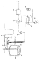
- the figure shows a diagram of an electric furnace with a relative electrode and an actuation and control circuit according to the invention.
- an electric arc furnace 10 with scrap 17 to be smelted within it cooperates with electrodes 11 borne by an arm 12 actuated vertically by an operational cylinder 13.
- Each electrode 11 is fed by its own high-voltage line 14 fed and controlled by its own regulation system.
- the operational cylinder 13 is fed by a system 21 which delivers fluid under pressure and which may cooperate with a pressure storage vessel 20.
- the operational cylinder 13 is fed through a quick-response control servovalve 18, and a continuous pressure transducer 15 is comprised in the immediate vicinity of the operational cylinder 13 and may be of a thermally compensated type.
- This continuous pressure transducer 15 which is substantially installed on the cylinder 13, provides continuous real information for a processor system 16, which on the one hand governs the servovalve 18 and on the other hand receives information from and supplies it to an interface 19 of the system which regulates the electrical current fed to the electrodes 11.
- the processor system 16 receives information from the pressure transducer 15 at preset and predeterminable intervals.
- systems with a linear transducer or a limit switch 22 may be comprised to control the terminal positions of the arm 12 that bears the electrodes 11.
- the pressure transducer 15 When the arm 12 is in a raised position, the pressure transducer 15 memorises the static pressure and supplies information to the processor system 16, which calculates the weight of the system consisting of the electrode, the arm and the burdening part of the operational cylinder 13.
- the pressure transducer 15 reads the dynamic pressure and supplies this information to the processor system 16, which stores the static pressure plus the dynamic pressure differential.
- the processor system 16 applies an intervention value differing by less than 1% (but any percentage intervention threshold could be selected) from the dynamic pressure value received from the pressure transducer 15 acting on the cylinder 13.
- the pressure transducer 15 monitoring continuously this variation in dynamic and static pressures, supplies this information to the processor system 16, which takes corrective action on the quick-response servovalve 18, which causes the electrode 11 to be lifted and keeps it at a static pressure value read by the pressure transducer 15 and required by the processor system 16.
- the processor system 16 does not intervene but lets the force of the weight of the electrode act upon and perforate the insulating layer.
- the processor system 16 can also apply a pressure to act on the electrode to assist the latter to perforate the insulating layer.
Landscapes
- Engineering & Computer Science (AREA)
- Power Engineering (AREA)
- Physics & Mathematics (AREA)
- Plasma & Fusion (AREA)
- Discharge Heating (AREA)
- Furnace Details (AREA)
Claims (8)
- Procédé de commande de la force appliquée sur les bras porte-électrode (12) d'un four à arc électrique (10), la régulation verticale des électrodes (11) étant réalisée avec un système électro-hydraulique ou électro-pneumatique (20-21) constitué d'un cylindre d'actionnement (13) actionné par un fluide sous pression de manière à relever et abaisser les électrodes (11), les moyens de contrôle du cylindre d'actionnement (13) pouvant être ajustés au moyen d'un dispositif électrique (18), procédé dans lequel la pression de travail du cylindre d'actionnement (13) est mesurée par un transducteur de pression (15) et est corrélée par un système à processeur (16) avec le poids des électrodes (11) et avec le niveau de pression statique, le système à processeur (16) gouvernant une servo-vanne (18) à réponse rapide et étant gouverné par un interface (19) du système qui ajuste le courant électrique alimentant les électrodes (11), procédé dans lequel la pression statique est lue et conservée chaque fois que l'électrode (11) est dans sa position relevée, tandis que lorsque l'électrode (11) passe de sa position relevée à sa position de travail le long d'un premier segment initial de son parcours, le transducteur de pression (15) lit la pression dynamique et fournit cette valeur au système à processeur (16) qui conserve en mémoire cette valeur de la pression dynamique et l'ajoute à la valeur de la pression statique, le système à processeur (16) fournissant une valeur d'intervention qui est définie par un seuil voulu de déviation par rapport à la valeur conservée en mémoire.
- Procédé selon la revendication 1, dans lequel le système à processeur (16) provoque le relèvement de l'électrode (11) sauf si l'interface (19) donne un avertissement contraire lorsque la pression dynamique se trouve à l'intérieur d'une plage déterminée.
- Procédé selon la revendication 1 ou 2, dans lequel chaque fois que l'interface (19) avertit que l'arc ne s'est pas allumé, le système à processeur (16) commande une surpression sur l'électrode (11) si la pression statique tombe rapidement en dessous de la valeur de la pression statique conservée en mémoire en liaison avec l'état où l'électrode (11) est en position relevée.
- Procédé selon l'une quelconque des revendications précédentes, dans lequel lorsque l'électrode (11) s'appuie sur les mitrailles (17), le transducteur de pression (15) avertit le système à processeur (16) qui commande la servo-vanne (18) et entraîne le relèvement et le maintien de l'électrode (11) à la valeur pré-réglée de la pression si l'interface (19) indique que l'arc s'est allumé.
- Dispositif de commande de la force appliquée sur les bras porte-électrode (12) d'un four à arc électrique (10), l'ajustement vertical des électrodes (11) étant réalisé avec un système électro-hydraulique ou électro-pneumatique (20-21) constitué d'un cylindre d'actionnement (13) actionné par un fluide sous pression de manière à relever et abaisser des électrodes (11), les moyens de contrôle du cylindre d'actionnement (13) pouvant être ajustés au moyen d'un dispositif électrique (18), ce dispositif convenant pour exécuter le procédé des revendications précédentes, tandis qu'une servo-vanne (18) à réponse rapide est disposée sur la conduite de fluide sous pression alimentant le cylindre d'actionnement (13), tandis que des moyens pour lire la pression correspondante du cylindre d'actionnement (13) sont agencés sur le cylindre d'actionnement (13) , ces moyens étant du type à transducteur de pression (15), le transducteur de pression (15) étant relié à un système à processeur (16) qui échange dans les deux sens des informations avec un interface (19) du système qui commande l'ajustement du courant électrique alimentant les électrodes (11) et commande également la servo-vanne (18) à réponse rapide, le dispositif étant caractérisé en ce que le système à processeur (16) est associé aux moyens (15) lisant la pression correspondante du cylindre d'actionnement (13), et en ce qu'il comprend des moyens pour conserver en mémoire le poids de l'électrode (11) lorsque cette dernière (11) est dans une position relevée quelconque, en même temps que des moyens pour conserver en mémoire le poids du bras (12) plus le poids chargeant le cylindre d'actionnement (13), et comprend également des moyens pour conserver en mémoire la pression dynamique chaque fois que l'électrode (11) commence sa descente depuis sa position relevée, et est également caractérisé en ce que le transducteur de pression (15) est installé au voisinage du cylindre d'actionnement (13).
- Dispositif selon la revendication 5, dans lequel le transducteur de pression (15) comporte des moyens pour la compensation de la température.
- Dispositif selon la revendication 5 ou 6, dans lequel le transducteur de pression (15) fournit périodiquement au système à processeur (16) une mesure de la pression de travail.
- Dispositif selon la revendication 5 ou 6, dans lequel le transducteur de pression (15) fournit en continu au système à processeur (16) une mesure de la pression de travail.
Applications Claiming Priority (2)
| Application Number | Priority Date | Filing Date | Title |
|---|---|---|---|
| IT8344690 | 1990-07-23 | ||
| IT83446A IT1242380B (it) | 1990-07-23 | 1990-07-23 | Procedimento e dispositivo per il controllo della forza applicata sui bracci porta elettrodi del forno elettrico ad arco |
Publications (2)
| Publication Number | Publication Date |
|---|---|
| EP0475008A1 EP0475008A1 (fr) | 1992-03-18 |
| EP0475008B1 true EP0475008B1 (fr) | 1995-09-06 |
Family
ID=11322014
Family Applications (1)
| Application Number | Title | Priority Date | Filing Date |
|---|---|---|---|
| EP91111325A Expired - Lifetime EP0475008B1 (fr) | 1990-07-23 | 1991-07-08 | Procédé et dispositif de commande de la force appliquée au bras de support pour électrode d'un four à arc |
Country Status (6)
| Country | Link |
|---|---|
| US (1) | US5274664A (fr) |
| EP (1) | EP0475008B1 (fr) |
| AT (1) | ATE127649T1 (fr) |
| DE (1) | DE69112744T2 (fr) |
| ES (1) | ES2075918T3 (fr) |
| IT (1) | IT1242380B (fr) |
Families Citing this family (12)
| Publication number | Priority date | Publication date | Assignee | Title |
|---|---|---|---|---|
| NO306439B1 (no) * | 1998-03-31 | 1999-11-01 | Elkem Materials | Veiing av forbrukbare elektroder i elektriske smelteovner |
| NO307110B1 (no) * | 1998-07-01 | 2000-02-07 | Elkem Materials | Fremgangsmåte for estimering av elektrodespissposisjon |
| WO2000008432A2 (fr) * | 1998-08-05 | 2000-02-17 | Cardio Technologies, Inc. | Dispositif de mesure de la pression |
| US7251693B2 (en) * | 2001-10-12 | 2007-07-31 | Direct Computer Resources, Inc. | System and method for data quality management and control of heterogeneous data sources |
| DE10311426B4 (de) * | 2002-12-20 | 2016-06-16 | Arndt Dung | Einspannung für eine auswechselbare Elektrode eines Elektroschmelzaggregats |
| CN100525552C (zh) * | 2006-03-10 | 2009-08-05 | 哈尔滨工业大学 | 用于等离子体电弧加热器的可在强电磁干扰环境下工作的气体工作介质转换装置 |
| KR101009884B1 (ko) | 2008-07-25 | 2011-01-19 | 현대제철 주식회사 | 전기로 전극 절손 방지 장치 및 그 방법 |
| DE102010052086A1 (de) * | 2010-03-10 | 2011-09-15 | Sms Siemag Ag | Elektrodentragarmsystem |
| EP2776770B1 (fr) * | 2011-11-07 | 2016-02-10 | GrafTech International Holdings Inc. | Système de surveillance de la consommation d'électrode |
| ITUB20160079A1 (it) * | 2016-01-19 | 2017-07-19 | Fast Tech S R L | Dispositivo di posizionamento di almeno un elettrodo per forni fusori. |
| DE102017001533B4 (de) * | 2017-02-15 | 2025-10-16 | Liebherr-Werk Ehingen Gmbh | Vorrichtung und Verfahren zur Ballastwiegung an einem Kran sowie ein entsprechender Kran |
| US12025376B2 (en) * | 2020-04-22 | 2024-07-02 | Billy Bryant | Method and system for detection of low quality graphite electrode on an EAF |
Family Cites Families (14)
| Publication number | Priority date | Publication date | Assignee | Title |
|---|---|---|---|---|
| US3614284A (en) * | 1969-04-12 | 1971-10-19 | Leybold Heraeus Verwaltung | Melting furnace with movable current carrying leads for a consumable electrode |
| US3650311A (en) * | 1969-05-14 | 1972-03-21 | Sandel Ind Inc | Method for homogeneous refining and continuously casting metals and alloys |
| SU418991A1 (ru) * | 1971-12-27 | 1974-03-05 | В. В. Салмик, Г. И. Поликарпов , Ф. Ф. иТаоуров | ЭЛЕКТРОД ОД ЕРЖАТЕЛЬ ДУГОВОЙ ЭЛЕКТРОПЕЧИ1Изобретение относитс к электротехнической !!рол1ь:шленпости, в частности к дуговым плавильным электропечам с гидравлическими приводами перемещени электродов.Дл за>&х:;л1а и освобождени электродов обыч'мо исасльзуегс ируж;:'!ло-];нсв:.;а, л-'е- СКИЙ vi/;H ирлокИ'ПНО-ГМДр? вличес <нп ^;av;:•MiЗлл,i причем зажим осуш,ествл етс пружиной, а освобождение — лневматкиеским или гидрав.и^-К Недостаткам таких механизмов относитс нестабильность уск:лч за/к^ша из-за л.ефслл:::- ций пружины и 1Пт01\ , оО;"ьи!ие габао^-гы и сложность {т^лчажшлх сисгем.Цель ипобретсник состоит в том, чтобы обес- не-ить )'вели':ен;1е давлени в контакте I'oловок л>&лгктродол,ср>&!^а'гелой с э .о;<1Л)олал1Л, умсньштпъ габариты элгктрол,одержате.л и упростить его констр\л\ц1по.В предлагаемом электрододержателе дуговой электроиечи это достигаетс тем, что полость цилиндра зажпма электрода еоединены с полостью ги.дроцилиндра перемещелик элек- трододержател через распределитель с электромагнитным управлением, соединенный I'n сливом гидросистемы гибким рукавом.На фиг. 1 изображен иредлагаемый электро- додержатель в разрезе, на фиг. 2 и 3 изобра- ;жена схема управлени зажимом электрода в двух положени х (зажатом и освобожденном).Элекгро.,олер'-чатель дугспои этектролечи состоит из стопчи / электрододержагел , рукава 2 с KopiAvoM 5, несуп],;;л! электрод 4, штока 5 дл за;-кил:г "^'ччтрода со слабей созврат- пой иружччой 6 ч ч ос;^обс>&кчеп1: эло.^гро.ча 4, н;:>&к:;м"С10 ччл ;;i .ча 7 с :'абочей поло:'1;>&ю 8, чоед]:?!с;;чс;! тчу;;ч л'чгзодом 9 с рч:',р::до.-!;;то- лем 'О с з,_ек:чг-.:аг!титпь::,1 учрал'::п;!ем, который в C!ic;o очсчсдь соедчиен тр^Ч)оироводол1 11 с рабочей I'o гостью 12 гчдрО:.1,;;л 1л;дра 13 перемчшччч э елтрододерч-гате, i5 со слив- глчд! Г1'б1-;;;л[ рук/чюм 14, в котор'чй через тру- бочпочсд lit с ч ччютс т; кже \Ч'счкп 1!3 ци-30делител Ш, трубопроводов 9 и 11 рабочей полости 12, гид!10;дплп;!дра 13 иереме;'(,ем!; электрододержател с pa6o4eii иочюсгыо 8 цилиндра 7 зал-:има электрода 4 1иток 5 выдвигаетс , зажима и удержива электрод 4 в корпусе 5 и сж]1^1а слабую возвратную пру-Ж'ИНу 6.Дл освобождени электрода 4 при иереиус- ке расиредел11тель 10 перекрывает трубопровод //, отсоедин полость J2 гидроцилиндра 13 от полости 8 цилиндра 7, одновременно соедин полость 8 и трубопровод 9 со сливным |
| DE2312603C2 (de) * | 1973-03-14 | 1974-10-03 | Demag Ag, 4100 Duisburg | Einrichtung zur Verhinderung von Elektrodenbrüchen bei Lichtbogenofen mit einer elektrohydraulischen bzw. pneumatischen Elektrodenregelung |
| US3937869A (en) * | 1974-10-08 | 1976-02-10 | Republic Steel Corporation | Force sensing control apparatus and method for electric arc furnaces |
| US4131754A (en) * | 1977-05-02 | 1978-12-26 | Consarc Corporation | Automatic melt rate control system for consumable electrode remelting |
| FR2402993A1 (fr) * | 1977-09-09 | 1979-04-06 | Siderurgie Fse Inst Rech | Procede et dispositif de prevention de la casse des electrodes dans un four a arcs |
| DE2930563A1 (de) * | 1979-07-27 | 1981-02-12 | Vitkovice Zelezarny | Einrichtung zur bruchverhinderung von lichtbogenelektroden in oefen |
| BE880472A (fr) * | 1979-12-06 | 1980-04-01 | Cockerill | Dispositif de securite pour electrodes d'un four electrique d'acierie |
| US4303797A (en) * | 1980-06-20 | 1981-12-01 | Consarc Corporation | Method and apparatus for controlling electrode drive speed in a consumable electrode furnace |
| SU936471A2 (ru) * | 1980-11-05 | 1982-06-15 | Специальное Проектно-Конструкторское И Технологическое Бюро Электротермического Оборудования | Устройство дл регулировани электрического режима дуговой электропечи |
| DE3242934A1 (de) * | 1982-11-20 | 1984-05-24 | Mannesmann Rexroth GmbH, 8770 Lohr | Regeleinrichtung fuer die hoehenverstellung der elektrode eines lichtbogenofens |
| SU1229980A1 (ru) * | 1984-07-11 | 1986-05-07 | Новоджамбулский Фосфорный Завод | Способ управлени гидроприводом перемещени электродов рудно-термической печи |
| DE3528867A1 (de) * | 1985-08-12 | 1987-02-19 | Leybold Heraeus Gmbh & Co Kg | Einrichtung zum kompensieren des einflusses des gewichts einer stromzufuehrungsleitung auf eine gewichtsmesseinrichtung |
-
1990
- 1990-07-23 IT IT83446A patent/IT1242380B/it active IP Right Grant
-
1991
- 1991-07-08 AT AT91111325T patent/ATE127649T1/de not_active IP Right Cessation
- 1991-07-08 ES ES91111325T patent/ES2075918T3/es not_active Expired - Lifetime
- 1991-07-08 EP EP91111325A patent/EP0475008B1/fr not_active Expired - Lifetime
- 1991-07-08 DE DE69112744T patent/DE69112744T2/de not_active Expired - Fee Related
- 1991-07-23 US US07/734,785 patent/US5274664A/en not_active Expired - Lifetime
Also Published As
| Publication number | Publication date |
|---|---|
| IT1242380B (it) | 1994-03-04 |
| ATE127649T1 (de) | 1995-09-15 |
| IT9083446A0 (it) | 1990-07-23 |
| IT9083446A1 (it) | 1992-01-23 |
| US5274664A (en) | 1993-12-28 |
| EP0475008A1 (fr) | 1992-03-18 |
| DE69112744T2 (de) | 1996-02-22 |
| DE69112744D1 (de) | 1995-10-12 |
| ES2075918T3 (es) | 1995-10-16 |
Similar Documents
| Publication | Publication Date | Title |
|---|---|---|
| US5274664A (en) | Method and device to control the force applied to the electrode-bearing arms of an electric arc furnace | |
| US4861960A (en) | Real time adaptive control for resistance spot welding process | |
| EP0042689B1 (fr) | Procédé et appareil pour régler la vitesse d'actionnement d'une électrode dans un four à électrode consumable | |
| US4718931A (en) | Method of controlling melting in a cold crown glass melter | |
| US4000361A (en) | Electroslag remelting furnace with relative displacement of a mould and an ingot being cast | |
| EP0095352A2 (fr) | Procédé et dispositif pour la production de bandes métalliques solidifiées rapidement par un système à deux cylindres | |
| US4131754A (en) | Automatic melt rate control system for consumable electrode remelting | |
| US4075414A (en) | Apparatus for regulating the immersion depth of electrodes in electrode-melting furnaces | |
| US5539768A (en) | Electric arc furnace electrode consumption analyzer | |
| US4730337A (en) | Method and apparatus for operating a direct-current arc furnace | |
| KR100442577B1 (ko) | 수치제어장치 | |
| CA1169899A (fr) | Methode et appareil utilises pour la regulation de la fusion d'une electrode au cours de la refonte de l'electrolaitier | |
| US3937869A (en) | Force sensing control apparatus and method for electric arc furnaces | |
| GB1426019A (en) | Process and apparatus for heating a furnace | |
| US4180121A (en) | Low pressure molten metal casting device | |
| FR2677284B1 (fr) | Procede et appareillage pour la coulee automatique de demi-produits. | |
| US3187078A (en) | Electrode regulating system for arc melting furnaces | |
| US3385920A (en) | Control system for consumable electrode furnace | |
| EP0189313A2 (fr) | Procédé et dispositif pour compenser la perte de pression métallostatique pendant la coulée d'un métal liquide sur une surface refroidie mouvante | |
| EP0137239A1 (fr) | Procédé et dispositif pour le contrôle automatique du niveau | |
| US4977951A (en) | Apparatus for flow control of molten material by force detection | |
| US20020141475A1 (en) | Control of electrode depth in electroslag remelting | |
| US5090603A (en) | Metal pouring system | |
| EP1068496B1 (fr) | Procede pour peser des electrodes dans des fours electriques de fusion | |
| US3994351A (en) | Scale controller |
Legal Events
| Date | Code | Title | Description |
|---|---|---|---|
| PUAI | Public reference made under article 153(3) epc to a published international application that has entered the european phase |
Free format text: ORIGINAL CODE: 0009012 |
|
| AK | Designated contracting states |
Kind code of ref document: A1 Designated state(s): AT BE CH DE DK ES FR GB GR IT LI LU NL SE |
|
| 17P | Request for examination filed |
Effective date: 19920904 |
|
| 17Q | First examination report despatched |
Effective date: 19931126 |
|
| GRAA | (expected) grant |
Free format text: ORIGINAL CODE: 0009210 |
|
| ITF | It: translation for a ep patent filed | ||
| AK | Designated contracting states |
Kind code of ref document: B1 Designated state(s): AT BE CH DE DK ES FR GB GR IT LI LU NL SE |
|
| PG25 | Lapsed in a contracting state [announced via postgrant information from national office to epo] |
Ref country code: DK Effective date: 19950906 Ref country code: NL Free format text: LAPSE BECAUSE OF FAILURE TO SUBMIT A TRANSLATION OF THE DESCRIPTION OR TO PAY THE FEE WITHIN THE PRESCRIBED TIME-LIMIT Effective date: 19950906 Ref country code: GR Free format text: LAPSE BECAUSE OF FAILURE TO SUBMIT A TRANSLATION OF THE DESCRIPTION OR TO PAY THE FEE WITHIN THE PRESCRIBED TIME-LIMIT Effective date: 19950906 Ref country code: LI Effective date: 19950906 Ref country code: CH Effective date: 19950906 |
|
| REF | Corresponds to: |
Ref document number: 127649 Country of ref document: AT Date of ref document: 19950915 Kind code of ref document: T |
|
| REF | Corresponds to: |
Ref document number: 69112744 Country of ref document: DE Date of ref document: 19951012 |
|
| ET | Fr: translation filed | ||
| REG | Reference to a national code |
Ref country code: ES Ref legal event code: FG2A Ref document number: 2075918 Country of ref document: ES Kind code of ref document: T3 |
|
| NLV1 | Nl: lapsed or annulled due to failure to fulfill the requirements of art. 29p and 29m of the patents act | ||
| REG | Reference to a national code |
Ref country code: CH Ref legal event code: PL |
|
| PLBQ | Unpublished change to opponent data |
Free format text: ORIGINAL CODE: EPIDOS OPPO |
|
| PLBI | Opposition filed |
Free format text: ORIGINAL CODE: 0009260 |
|
| PG25 | Lapsed in a contracting state [announced via postgrant information from national office to epo] |
Ref country code: LU Free format text: LAPSE BECAUSE OF NON-PAYMENT OF DUE FEES Effective date: 19960731 |
|
| 26 | Opposition filed |
Opponent name: MANNESMANN AKTIENGESELLSCHAFT Effective date: 19960606 |
|
| PLBF | Reply of patent proprietor to notice(s) of opposition |
Free format text: ORIGINAL CODE: EPIDOS OBSO |
|
| PLBF | Reply of patent proprietor to notice(s) of opposition |
Free format text: ORIGINAL CODE: EPIDOS OBSO |
|
| PLBO | Opposition rejected |
Free format text: ORIGINAL CODE: EPIDOS REJO |
|
| PLBN | Opposition rejected |
Free format text: ORIGINAL CODE: 0009273 |
|
| STAA | Information on the status of an ep patent application or granted ep patent |
Free format text: STATUS: OPPOSITION REJECTED |
|
| 27O | Opposition rejected |
Effective date: 19980319 |
|
| PGFP | Annual fee paid to national office [announced via postgrant information from national office to epo] |
Ref country code: SE Payment date: 20000705 Year of fee payment: 10 |
|
| PG25 | Lapsed in a contracting state [announced via postgrant information from national office to epo] |
Ref country code: SE Free format text: LAPSE BECAUSE OF NON-PAYMENT OF DUE FEES Effective date: 20010709 |
|
| REG | Reference to a national code |
Ref country code: GB Ref legal event code: IF02 |
|
| EUG | Se: european patent has lapsed |
Ref document number: 91111325.6 |
|
| PGFP | Annual fee paid to national office [announced via postgrant information from national office to epo] |
Ref country code: AT Payment date: 20060628 Year of fee payment: 16 |
|
| PG25 | Lapsed in a contracting state [announced via postgrant information from national office to epo] |
Ref country code: AT Free format text: LAPSE BECAUSE OF NON-PAYMENT OF DUE FEES Effective date: 20070708 |
|
| PGFP | Annual fee paid to national office [announced via postgrant information from national office to epo] |
Ref country code: ES Payment date: 20080718 Year of fee payment: 18 Ref country code: DE Payment date: 20080730 Year of fee payment: 18 |
|
| PGFP | Annual fee paid to national office [announced via postgrant information from national office to epo] |
Ref country code: FR Payment date: 20080730 Year of fee payment: 18 Ref country code: IT Payment date: 20080717 Year of fee payment: 18 |
|
| PGFP | Annual fee paid to national office [announced via postgrant information from national office to epo] |
Ref country code: GB Payment date: 20080630 Year of fee payment: 18 |
|
| PGFP | Annual fee paid to national office [announced via postgrant information from national office to epo] |
Ref country code: BE Payment date: 20080722 Year of fee payment: 18 |
|
| BERE | Be: lapsed |
Owner name: *DANIELI & C. OFFICINE MECCANICHE S.P.A. Effective date: 20090731 |
|
| GBPC | Gb: european patent ceased through non-payment of renewal fee |
Effective date: 20090708 |
|
| REG | Reference to a national code |
Ref country code: FR Ref legal event code: ST Effective date: 20100331 |
|
| PG25 | Lapsed in a contracting state [announced via postgrant information from national office to epo] |
Ref country code: FR Free format text: LAPSE BECAUSE OF NON-PAYMENT OF DUE FEES Effective date: 20090731 |
|
| PG25 | Lapsed in a contracting state [announced via postgrant information from national office to epo] |
Ref country code: GB Free format text: LAPSE BECAUSE OF NON-PAYMENT OF DUE FEES Effective date: 20090708 |
|
| PG25 | Lapsed in a contracting state [announced via postgrant information from national office to epo] |
Ref country code: BE Free format text: LAPSE BECAUSE OF NON-PAYMENT OF DUE FEES Effective date: 20090731 Ref country code: DE Free format text: LAPSE BECAUSE OF NON-PAYMENT OF DUE FEES Effective date: 20100202 |
|
| REG | Reference to a national code |
Ref country code: ES Ref legal event code: FD2A Effective date: 20090709 |
|
| PG25 | Lapsed in a contracting state [announced via postgrant information from national office to epo] |
Ref country code: ES Free format text: LAPSE BECAUSE OF NON-PAYMENT OF DUE FEES Effective date: 20090709 |
|
| PG25 | Lapsed in a contracting state [announced via postgrant information from national office to epo] |
Ref country code: IT Free format text: LAPSE BECAUSE OF NON-PAYMENT OF DUE FEES Effective date: 20090708 |