EP0475120A1 - Mécanisme d'alimentation en encre pour grandes vitesses - Google Patents
Mécanisme d'alimentation en encre pour grandes vitesses Download PDFInfo
- Publication number
- EP0475120A1 EP0475120A1 EP91113788A EP91113788A EP0475120A1 EP 0475120 A1 EP0475120 A1 EP 0475120A1 EP 91113788 A EP91113788 A EP 91113788A EP 91113788 A EP91113788 A EP 91113788A EP 0475120 A1 EP0475120 A1 EP 0475120A1
- Authority
- EP
- European Patent Office
- Prior art keywords
- roller
- ink
- transfer roller
- transfer
- contact
- Prior art date
- Legal status (The legal status is an assumption and is not a legal conclusion. Google has not performed a legal analysis and makes no representation as to the accuracy of the status listed.)
- Withdrawn
Links
Images


Classifications
-
- B—PERFORMING OPERATIONS; TRANSPORTING
- B41—PRINTING; LINING MACHINES; TYPEWRITERS; STAMPS
- B41F—PRINTING MACHINES OR PRESSES
- B41F31/00—Inking arrangements or devices
- B41F31/004—Driving means for ink rollers
-
- B—PERFORMING OPERATIONS; TRANSPORTING
- B41—PRINTING; LINING MACHINES; TYPEWRITERS; STAMPS
- B41F—PRINTING MACHINES OR PRESSES
- B41F31/00—Inking arrangements or devices
- B41F31/02—Ducts, containers, supply or metering devices
- B41F31/14—Applications of messenger or other moving transfer rollers
-
- B—PERFORMING OPERATIONS; TRANSPORTING
- B41—PRINTING; LINING MACHINES; TYPEWRITERS; STAMPS
- B41P—INDEXING SCHEME RELATING TO PRINTING, LINING MACHINES, TYPEWRITERS, AND TO STAMPS
- B41P2213/00—Arrangements for actuating or driving printing presses; Auxiliary devices or processes
- B41P2213/40—Auxiliary devices or processes associated with the drives
- B41P2213/42—Vibration-dampers for machine parts
Definitions
- the present invention relates to a printing machine, particularly a high speed ink supply mechanism for a printing machine.
- the ink fountain roller is driven to rotate at a relatively slow peripheral speed as it picks up ink from the ink fountain.
- the plate cylinder is driven so that it rotates at the relatively high surface speed of the running web to be printed.
- the distribution roller and the other ink transfer rollers are driven via a common gear train with the plate cylinder and at a relatively high speed in comparison to the ink fountain roller.
- the reciprocating lift roller is driven by surface contact with either the ink fountain roller or the friction roller depending on their position and therefore undergoes repeated changes in peripheral speed. As a result, the reciprocating lifting roller comes back from the ink fountain roller to the rubbing roller at a peripheral speed which is lower than that of the rubbing roller.
- the present invention provides a printing unit in which a colored printing image is transferred away from a plate cylinder with a minimum of impairment caused by a change in the peripheral speed of a lifting roller.
- a printing unit comprises an ink fountain containing a supply of ink, an ink fountain roller for receiving ink from the ink fountain, a first transfer roller, and a movable lifting roller for transferring ink from the ink fountain roller to the first transfer roller.
- the lifting roller has a first position in which it is in ink-transferring contact with the ink fountain roller and a second position in which it is not in ink-transferring contact with the ink fountain roller.
- a reciprocating mechanism is provided to move the lift roller between the first and second positions.
- a second transfer roller is held in ink transfer contact with the first transfer roller and a plate cylinder is provided which carries the image to be printed.
- a first drive mechanism drives the first transfer roller.
- a second drive mechanism drives the second transfer roller and the plate cylinder independently of the drive of the first transfer roller.
- the invention prevents the reciprocating lift roller from interfering with the rotation of the plate cylinder because the plate cylinder is driven independently of the drive of the transfer roller which is affected by the repeatedly changing speed of the reciprocating lift roller.
- the drive mechanism preferably comprises a first gear mechanism for driving the first transfer roller, a first motor for driving the first gear mechanism, a second gear mechanism independent of the first gear mechanism for driving the second transfer roller and the plate cylinder, and a second motor for driving the second gear mechanism.
- This arrangement ensures that the gear train which drives the second transfer roller and the plate cylinder is not affected by the changing speed of the reciprocating lifting roller.
- This embodiment of the invention also prevents the reciprocating lifting roller from interfering with the rotation of the plate cylinder, since the plate cylinder has a drive independent of the drive of the first transfer roller and consequently it is not affected by the impact of the reciprocating ones Lift roller on the first transfer roller experienced.
- the vibrating roller is held in a non-contact position so that it is not in ink-transferring contact with the second transfer roller when the lift roller strikes the first transfer roller. This ensures that the torsional vibration between the first and the second transfer roller surface is not transferred.
- the vibrating roller is movable between a first position in which it is not in ink-transferring contact with the second transfer roller and a second position in which it is in ink-transferring contact with the second transfer roller.
- a holding device is provided to keep the vibrating roller out of the second position when the lifting roller is in the first position.
- the elevating roller and the vibrating roller are mounted together on a frame which is pivoted about the axis of the first transfer roller to move the elevating roller and the vibrating roller into their respective positions.
- This alternative embodiment of the invention also prevents the lift roller from interfering with the rotation of the plate cylinder because the vibrating roller is kept out of ink transfer contact with the second transfer roller when the lift roller experiences a slowdown due to surface contact with the slower rotating ink fountain roller.
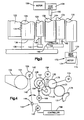
- the printing unit 10 is, for example, an offset printing machine which comprises a plurality of rollers for transferring printing ink from an ink fountain 11 to a plate cylinder 12 which bears an image to be printed.
- a blanket cylinder 14 transfers the inked print image from the plate cylinder 12 on the running paper web 16.
- An ink fountain roller 18 receives ink from the ink fountain 11.
- a lift roller 20 reciprocates between the ink fountain roller 18 and the first transfer roller 22 to transfer ink from the ink fountain roller 18 to the first transfer roller 22.
- the first transfer roller 22 is an axially reciprocating friction roller.
- the lifting roller 20 is moved between the ink fountain roller 18 and the first transfer roller 22 by a reciprocating mechanism 24.
- the reciprocating mechanism 24 comprises a pivotable arm 26 which carries the lifting roller 20 and is mounted on a hub 28 for pivoting movement.
- a reciprocating motor 29 moves the pivotable arm 26 around the hub 28 to repeatedly move the lift roller 20 in one cycle between the ink fountain roller 18 and the first transfer roller 22.
- a second transfer roller 30 and a series of additional transfer rollers 32 transfer ink from the first transfer roller 22 to a group of applicator rollers 34, which in turn transfer the ink to the plate cylinder 12.
- the printing unit 10 further comprises a fountain solution reservoir 40 and a series of dampening rollers 42 for transferring a dampening film to the plate cylinder 12.
- a second blanket cylinder 44 is only partially shown in FIG. 1 to show a second printing unit for simultaneous printing on the other side of the paper web 16 .
- the printing unit 10 also includes a series of drive mechanisms consisting of motors and gears for rotating the various rollers.
- the gears assigned to the various rollers are shown schematically in the figures by circular dotted lines. Individual gears and gear mechanisms for rotating the rolls can be of conventional construction known to those skilled in the art.
- An ink fountain roller motor 48 drives a gear mechanism 50 which rotates the ink fountain roller 18 at a relatively low peripheral speed to receive ink from the ink fountain 11.
- the second transfer roller 30, the additional transfer rollers 32, the applicator roller 34, the plate cylinder 12 and the blanket cylinder 14 are connected by a common gear train 51 to be rotated together.
- the conventional gear train 51 is independent of the gear mechanism 50.
- a gear gear motor 52 drives the common gear train 51 so that each roller connected thereto rotates at a peripheral speed which is approximately the same as the speed of the running paper web 16.
- a transfer roller motor 54 drives another gear mechanism 55 to rotate the first transfer roller 22 at a peripheral speed which is approximately the same as that of the running paper web. It is important that the transfer roller motor 54 and the further gear mechanism 55 rotate the first transfer roller 22, regardless of the rotation of the second transfer roller 30 and the other rollers which are driven together with the plate cylinder 12 by the gear train 51.
- the dampening rollers 42 are driven in a conventional manner by a dampening roller motor 56 and an associated gear train 58.
- the reciprocating mechanism 24 reciprocates the lift roller 20 between a first position shown in broken lines in FIG. 1 and a second position shown in solid lines.
- the surface of the lifting roller 20 In the first position, the surface of the lifting roller 20 is in ink-transferring contact with the surface of the ink fountain roller 18.
- the surface of the lifting roller 20 is also in rotationally driven contact with the surface of the rotating ink fountain roller 18. It goes without saying that in the state of the driven rotary contact there is a color film between the contacting roller surfaces.
- the lift roller 20 is held in the first position by the reciprocating mechanism 24 to receive an amount of ink and then moved to the second position.
- the lift roller 20 In the second position, the lift roller 20 is kept in rotational contact with the first transfer roller 22, with ink being transferred from the lift roller 20 to the first transfer roller 22 and then to the plate cylinder (12) and the blanket cylinder 14.
- a lifting cycle is completed when the lifting roller 20 is moved back to the first position for ink transfer contact with the ink fountain roller 18 to pick up ink again.
- the lift roller 20 In the first position, the lift roller 20 is driven by the relatively slow rotating ink fountain roller 18 and reaches a peripheral speed which is less than the peripheral speed of the first transfer roller 22.
- the first transfer roller 22 accelerates the lifting roller 20 to the higher peripheral speed of the first transfer roller 22.
- the impact of the slowly rotating lifting roller surface on the faster rotating transfer roller surface generates a torsional vibration which resists the uniform rotation of the first transfer roller 22 causes.
- This gate ionic vibration is transmitted to the gear mechanism 55 which is driven by the transfer roller motor 54.
- the reciprocating lifting roller 20 has this effect on the first transfer roller 22 and the gear mechanism 55 every time it is brought into contact with the first transfer roller 22.
- the second transfer roller 30 and the subsequent rollers which transfer ink from the second transfer roller 30 to the plate cylinder 12, are rotated together by the common gear mechanism 51 regardless of the rotation of the first transfer roller 22 by the gear mechanism 55
- the second transfer roller 30 and the subsequent rollers are isolated from the torsional vibration which is generated when the lifting roller 20 strikes the first transfer roller 22. In this way it is ensured that the inked printed image is transferred away from the plate cylinder 12 without experiencing interruptions caused by the repeated impacts of the reciprocating lifting roller 20.
- a printing unit 70 according to an alternative embodiment of the present invention is shown schematically in FIG. 2.
- the printing unit 70 comprises an ink fountain 71 with an ink fountain roller 72, a lifting roller 73, a first and a second transfer roller 74 and 75 and further transfer rollers 76, which lead to a plate cylinder (not shown).
- the lift roller 73 is held in position by a frame 78 where it is in continuous ink transfer contact with the first transfer roller 74.
- a regulating device comprises a bearing part 79, in which a journal shaft 80 of the lifting roller 73 is mounted.
- the bearing part 79 is located in a slot 82 in the frame 78 and can be adjusted so that the support position of the lifting roller 73 with respect to the first transfer roller 74 can be radially regulated.
- the frame 78 is mounted to pivot about the axis 84 of the first transfer roller 74 and is associated with a reciprocating mechanism 86 for movement between a first position shown in dashed lines and a second position shown in black lines.
- the reciprocating mechanism 86 consists of a pivotable arm 88 which is connected to the frame 78 and is mounted on a hub 90 for the pivoting movement.
- a reciprocating motor 91 moves the pivotable arm 88 about the hub 90 to move the frame 78 between the first and second positions in repeated cycles.
- the lift roller 73 is held in ink transfer and rotational contact with the ink fountain roller 72 when the frame 78 is in the first position, and is prevented from contacting the ink fountain roller 72 when the frame 78 is in the second position.
- the printing unit 70 also includes a device for rotating the rollers.
- a gear transmission motor 92 drives a gear transmission 93, through which the second transfer roller 75 and the additional transfer rollers 76 are rotated together with the plate cylinder.
- a separate transfer roller motor 94 drives a separate transmission mechanism 95 to rotate the first transfer roller 74 independently of the rollers which are driven by the gear transmission motor 92 via the gear transmission 93.
- the lift roller 73 transfers ink to the first transfer roller 74 as they rotate in contact with each other.
- the slowly moving surface of the ink fountain roller 72 causes resistance to the faster moving surface of the lift roller 73.
- This creates a torsional vibration where the surface of the lifting roller 73 is in contact with the surface of the first transfer roller 74.
- the torsional vibration is transmitted to the first transfer roller 74 and into the gear mechanism 95 which rotates the first transfer roller 74. Since the second transfer roller 75 is driven and rotated independently of the first, the torsional vibration is not transferred to the second transfer roller 75 and further via the gear train 93 to the plate cylinder.
- the torsional vibrations generated by these repeated impacts of the lifting roller 73 on the ink fountain roller 72 do not impair the smooth transfer of the inked printed image away from the plate cylinder.
- the regulating device enables that when the lifting roller 73 comes into contact with the first transfer roller 74, the pressing pressure on the contact surfaces can be regulated so that the lifting roller 73 is driven by the first transfer roller 74 and the lifting roller 73 simultaneously has a controlled slip with respect to the first transfer roller 74 is allowed in response to the resistance of the slow moving ink fountain roller 72 when the lift roller 73 is in the first position.
- the degree to which the first transfer roller 74 passes through the lifting roller 73 drives rotating surface contact, reduced by the slip created when the lifting roller 73 strikes the ink fountain roller 72. This reduces the torsional vibration between the contacted surfaces of the lifting roller 73 and the first transfer roller 74.
- a reduction in the amount of the torsional vibration also serves to avoid impairment of the rotating plate cylinder, since a strong vibration could hit the surfaces of the first and second transfer rollers 74 and 75 which are close to each other in color-transferring contact are transferred.
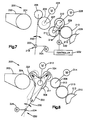
- a printing unit 120 comprises an ink fountain 122 with an ink fountain roller 124, a lifting roller 126, a first transfer roller 128 and a second transfer roller 130 at a distance from the first transfer roller 128. Furthermore, the printing unit 120 comprises an arrangement of rollers 131 leading to the plate cylinder (not shown) and an oscillating roller 132.
- the ink fountain 122 contains a quantity of ink and is equipped with metering knives 134 in a conventional manner.
- the ink fountain roller 124 has an axis 136 which is supported by an ink fountain roller drive mechanism 138 which includes a conventional type motor and transmission.
- the lifting roller 126 has an axis 140 which is supported by a pivotable arm 142 of a reciprocating mechanism 144 ( Figures 4 and 5).
- the pivotable arm 142 is supported on a hub 146 and is driven by a reciprocating motor 147 so that it rotates about the hub 146 around the lift roller 126 between positions for ink transfer contact with the ink fountain roller 124 and the first transfer roller 128 to move alternately.
- the first transfer roller 128 has an axis 150 which is supported at one end by a bearing part 152 and at the other end by a gear mechanism 154.
- the gear mechanism 154 is driven by a first motor 156 to rotate the first transfer roller 128.
- a movable frame 160 supports the axis 162 of the vibrating roller 132 so that it can be in continuous ink-transferring contact with the first transfer roller 128.
- the frame 160 may keep the vibrating roller 132 in rotational contact with the first transfer roller 128, or may include a gear mechanism for driving the vibrating roller 132 to rotate with the first transfer roller 128 driven by the first motor 156.
- the frame 160 is supported by the bearing part 152 so that it is rotatable about the axis 164 of the first transfer roller 128.
- a frame motor 166 is provided to move the frame 160 about the axis 164 and a control member 168 is pivoted to control the movement of the frame 160 by the frame motor 166 with the movement of the lift roller 126 to coordinate by the lift roller motor 147.
- a mechanical connection could be provided to coordinate the movements of a pivotable arm 142 and a frame 160.
- the second transfer roller 130 has an axis 170 which is supported by a drive mechanism 172.
- the drive mechanism 172 includes a motor 174 and a gear train 175 for driving the second transfer roller 130, the subsequent rollers 131 and the plate cylinder. These rollers are rotated independently of the first transfer roller 128 and the vibrating roller 132.
- the lifting roller 126 is moved back and forth between a first position in ink-transferring contact with the ink fountain roller 124 (FIG. 4) and a second position in ink-transferring contact with the first transfer roller 128 (FIG. 5).
- the reciprocating lift roller 126 encounters the first transfer roller 128, which has a peripheral speed that is less than the peripheral speed of the first transfer roller 128.
- the impact of the slower-moving elevator roller surface on the faster moving transfer roller surface generates a torsional vibration which causes resistance to the smooth rotation of the first transfer roller 128.
- the first transfer roller 128 is driven by the gear mechanism 154 and rotates independently of the second transfer roller 130, the subsequent rollers 131 and the plate cylinder, the torsional vibrations generated by the repeated impacts of the lifting roller 126 on the first transfer roller 128 are not applied to the gear transmission 175 Transfer which drives the plate cylinder.
- the inked print image is transferred away from the plate cylinder without being affected by the impact of the lifting roller 126 on the first transfer roller 128.
- the movement of the vibrating roller 132 on the frame 160 serves to prevent transmission of a torsional vibration from the surface of the first transfer roller 128 to the surface of the second transfer roller 130.
- the vibrating roller 132 has a contact position in which it is in ink-transferring contact with it and the second transfer roller 128 and 130 (Fig. 4) to bridge the gap between these rollers, and a non-contact position in which it is kept out of the ink-transferring contact with the second transfer roller 130 (Fig. 5) to the Open gap between these rollers.
- the controller 168 activates the frame motor 166 to move the frame 160 in a manner that the rocking roller 132 is kept out of the contact position when the lifting roller 126 is moved against the surface of the first transfer roller 128.
- the vibrating roller is only moved into the contact position after the torsional vibration caused by the impact of the lifting roller 126 has broken up.
- the torsional vibration can be broken up by the gear mechanism 154 before the lift roller 126 is moved out of contact position with the first transfer roller 128, and the movement of the vibration roller 132 on the frame 160 can be coordinated accordingly.
- a printing unit 200 comprises an ink fountain 202, an ink fountain roller 204, a lifting roller 206 and spaced apart first and second transfer rollers 208 and 210.
- the printing unit 200 also includes further successive rollers 212 which run from the second transfer roller 210 to a plate cylinder (not shown), and an oscillating roller 214 supported on a movable frame 216.
- a first motor 226 drives the first transfer roller 208 via a gear mechanism 227.
- a second motor 228 drives the second transfer roller 210, together with the successive rollers 212 and the plate cylinder, via a common gear mechanism 229, which is independent of the gear mechanism 227 driven by the first motor 226.
- the lifting roller 206 drives the first Transfer roller 208 isolates applied torsional vibrations from the gear train 229 which drives the plate cylinder.
- a frame motor 230 moves the frame 216 to move the vibrating roller 214 to a position where it is in ink transfer contact between the first and second transfer rollers 208 and 210 (FIG. 6) and a position where it is not in ink transfer contact with the first transfer roller 208 (Fig. 7).
- the printing unit 200 shown in FIGS. 6 and 7 differs from the printing unit shown in FIGS. 3 to 5 in that the frame 216 is mounted such that it can be pivoted about the axis of the second transfer roller 210 and not about the axis of the first Transfer roller 208.
- a control element 232 coordinates the movement of the vibrating roller 214 with the movement of the lifting roller 206 similar to the control element 168 to avoid the transmission of torsional vibrations from the surface of the first transfer roller 208 via the vibrating roller 214 to the surface of the second transfer roller 210 .
- a printing unit 300 according to a further alternative embodiment of the invention is shown in FIG. 8.
- the printing unit 300 comprises an ink fountain 302 with an ink fountain roller 304, spaced apart first and second transfer rollers 306 and 308, and additional transfer rollers 310, which lead to a plate cylinder (not shown).
- the first transfer roller 306 is rotated by a gear mechanism 311 which is driven by a first motor 312.
- the second transfer roller 308, the additional transfer rollers 310 and the plate cylinder are rotated by a gear transmission 313 which is driven by a second motor 314 and is independent of the gear mechanism 311 which rotates the first transfer roller 306.
- a movable frame 320 supports a lift roller 322 and an oscillating roller 324, which are in continuous ink-transferring and rotational contact with the first transfer roller 306.
- a pair of regulating members 326 allow regulating the degree to which the lift roller 322 and the vibratory roller 324 are held in rotational contact with the first transfer roller 306.
- the movable frame 320 is supported so that it can be pivoted about the axis of the first transfer roller 306 and is associated with a reciprocating mechanism 330 which is to be moved between a first position shown with black lines and a second position shown with dashed lines .
- the reciprocating mechanism 330 includes a pivotable arm 332 which is connected to the frame 320 and pivotally supported on a hub 334.
- the reciprocating arm 332 is moved about the hub 334 by the reciprocating motor 336 to repeatedly move the frame 320 in cycles between the first and second positions.
- the frame 320 When the frame 320 is in one second position is the lift roller 322 not in ink transfer contact with the ink fountain roller 304, and the vibratory roller 324 is in ink transfer contact with the second transfer roller 308 to bridge the gap between the first and second transfer rollers 306 and 308.
- the reciprocating motor 326 moves the frame 320 to move the lift roller 322 in and out of ink transfer contact with the ink fountain roller 304, the oscillation roller 324 moves in reverse out of and in ink transfer contact with the second transfer roller 308.
- the oscillation roller is prevented from the second transfer roller 308 when resistance to the rotation of the lift roller 322 by the first transfer roller 306 is caused by the slower rotating ink fountain roller 304, and the surface of the second transfer roller 308 is isolated from this rotation resistance.
- the plate cylinder which is rotated together with the second transfer roller 308 via the gear mechanism 313, is in turn isolated from the rotational resistance caused by the lifting roller 322.
Landscapes
- Inking, Control Or Cleaning Of Printing Machines (AREA)
- Rotary Presses (AREA)
Applications Claiming Priority (2)
| Application Number | Priority Date | Filing Date | Title |
|---|---|---|---|
| US58307490A | 1990-09-14 | 1990-09-14 | |
| US583074 | 1990-09-14 |
Publications (1)
| Publication Number | Publication Date |
|---|---|
| EP0475120A1 true EP0475120A1 (fr) | 1992-03-18 |
Family
ID=24331592
Family Applications (1)
| Application Number | Title | Priority Date | Filing Date |
|---|---|---|---|
| EP91113788A Withdrawn EP0475120A1 (fr) | 1990-09-14 | 1991-08-16 | Mécanisme d'alimentation en encre pour grandes vitesses |
Country Status (3)
| Country | Link |
|---|---|
| EP (1) | EP0475120A1 (fr) |
| JP (1) | JPH06340058A (fr) |
| CA (1) | CA2049154C (fr) |
Cited By (9)
| Publication number | Priority date | Publication date | Assignee | Title |
|---|---|---|---|---|
| DE4428403A1 (de) * | 1994-08-11 | 1996-02-15 | Roland Man Druckmasch | Verfahren und Heberantrieb zum Zuführen von Farbe im Heberfarbwerk einer Druckmaschine |
| DE19623224C1 (de) * | 1996-06-11 | 1997-09-11 | Roland Man Druckmasch | Antrieb für eine Druckmaschine |
| FR2761925A1 (fr) * | 1997-04-15 | 1998-10-16 | Roland Man Druckmasch | Unite d'encrage pour une machine d'impression rotative |
| EP0974461A3 (fr) * | 1998-07-21 | 2000-04-12 | MAN Roland Druckmaschinen AG | Système d'encrage à preneur pour une machine à imprimer |
| DE19732059C2 (de) * | 1997-07-25 | 2002-02-07 | Roland Man Druckmasch | Farbwerk für eine Rotationsdruckmaschine |
| US7117792B2 (en) | 2001-12-06 | 2006-10-10 | Koenig & Bauer Aktiengesellschaft | Method and devices for regulating at least one cylinder in a printing press |
| EP2127874A1 (fr) | 2008-05-27 | 2009-12-02 | Heidelberger Druckmaschinen AG | Procédé destiné au fonctionnement d'une presse |
| DE102004062876B4 (de) * | 2004-12-21 | 2012-07-12 | manroland sheetfed GmbH | Einstellbare Lagerung einer Heberwalze im Farbwerk einer Druckmaschine |
| CN113103759A (zh) * | 2020-12-29 | 2021-07-13 | 湖北天桥机械(风机)有限公司 | 一种曲面胶印机墨站装置 |
Citations (8)
| Publication number | Priority date | Publication date | Assignee | Title |
|---|---|---|---|---|
| GB403990A (en) * | 1932-05-06 | 1934-01-08 | Alfred Schlesinger | Improvements in inking apparatus and the method of operating the same |
| GB496110A (en) * | 1937-02-23 | 1938-11-23 | George Mann & Company 1932 Ltd | Improvements in and relating to inking apparatus for printing machines |
| US2248645A (en) * | 1938-03-14 | 1941-07-08 | Schlesinger Alfred | Inking device of printing machines |
| US2672093A (en) * | 1950-10-19 | 1954-03-16 | Cottrell C B & Sons Co | Ink distribution for high-speed rotary printing presses |
| FR2229551A1 (fr) * | 1973-05-16 | 1974-12-13 | Maschf Augsburg Nuernberg Ag | |
| EP0019073A1 (fr) * | 1979-05-18 | 1980-11-26 | M.A.N.-ROLAND Druckmaschinen Aktiengesellschaft | Dispositif d'encrage pour machine à imprimer |
| DE3929043A1 (de) * | 1988-09-06 | 1990-03-15 | Polygraph Leipzig | Farbwerk fuer druckmaschinen |
| DE3917074A1 (de) * | 1988-07-26 | 1990-05-10 | Polygraph Leipzig | Farbwerk |
-
1991
- 1991-08-14 CA CA 2049154 patent/CA2049154C/fr not_active Expired - Fee Related
- 1991-08-16 EP EP91113788A patent/EP0475120A1/fr not_active Withdrawn
- 1991-09-13 JP JP3261443A patent/JPH06340058A/ja active Pending
Patent Citations (8)
| Publication number | Priority date | Publication date | Assignee | Title |
|---|---|---|---|---|
| GB403990A (en) * | 1932-05-06 | 1934-01-08 | Alfred Schlesinger | Improvements in inking apparatus and the method of operating the same |
| GB496110A (en) * | 1937-02-23 | 1938-11-23 | George Mann & Company 1932 Ltd | Improvements in and relating to inking apparatus for printing machines |
| US2248645A (en) * | 1938-03-14 | 1941-07-08 | Schlesinger Alfred | Inking device of printing machines |
| US2672093A (en) * | 1950-10-19 | 1954-03-16 | Cottrell C B & Sons Co | Ink distribution for high-speed rotary printing presses |
| FR2229551A1 (fr) * | 1973-05-16 | 1974-12-13 | Maschf Augsburg Nuernberg Ag | |
| EP0019073A1 (fr) * | 1979-05-18 | 1980-11-26 | M.A.N.-ROLAND Druckmaschinen Aktiengesellschaft | Dispositif d'encrage pour machine à imprimer |
| DE3917074A1 (de) * | 1988-07-26 | 1990-05-10 | Polygraph Leipzig | Farbwerk |
| DE3929043A1 (de) * | 1988-09-06 | 1990-03-15 | Polygraph Leipzig | Farbwerk fuer druckmaschinen |
Non-Patent Citations (1)
| Title |
|---|
| DE-B-2 703 425 * |
Cited By (20)
| Publication number | Priority date | Publication date | Assignee | Title |
|---|---|---|---|---|
| DE4428403C2 (de) * | 1994-08-11 | 1996-07-11 | Roland Man Druckmasch | Heberantrieb einer Druckmaschine |
| US5685225A (en) * | 1994-08-11 | 1997-11-11 | Man Roland Druckmaschinen Ag | Apparatus and method for regulating ink distribution in a printing machine |
| US5784960A (en) * | 1994-08-11 | 1998-07-28 | Man Roland Druckmaschinen Ag | Apparatus and method for regulating ink distribution in a printing machine |
| DE4428403A1 (de) * | 1994-08-11 | 1996-02-15 | Roland Man Druckmasch | Verfahren und Heberantrieb zum Zuführen von Farbe im Heberfarbwerk einer Druckmaschine |
| US5826505A (en) * | 1996-06-11 | 1998-10-27 | Man Roland Druckmaschinen Ag | Drive for a printing press |
| DE19623224C1 (de) * | 1996-06-11 | 1997-09-11 | Roland Man Druckmasch | Antrieb für eine Druckmaschine |
| EP0812683A1 (fr) | 1996-06-11 | 1997-12-17 | MAN Roland Druckmaschinen AG | Entraînement pour une machine à imprimer |
| DE19715614B4 (de) * | 1997-04-15 | 2005-06-02 | Man Roland Druckmaschinen Ag | Farbwerk für eine Rotationsdruckmaschine |
| FR2761925A1 (fr) * | 1997-04-15 | 1998-10-16 | Roland Man Druckmasch | Unite d'encrage pour une machine d'impression rotative |
| DE19732059C2 (de) * | 1997-07-25 | 2002-02-07 | Roland Man Druckmasch | Farbwerk für eine Rotationsdruckmaschine |
| EP0974461A3 (fr) * | 1998-07-21 | 2000-04-12 | MAN Roland Druckmaschinen AG | Système d'encrage à preneur pour une machine à imprimer |
| US7117792B2 (en) | 2001-12-06 | 2006-10-10 | Koenig & Bauer Aktiengesellschaft | Method and devices for regulating at least one cylinder in a printing press |
| US7124683B2 (en) | 2001-12-06 | 2006-10-24 | Koenig & Bauer Aktiengesellschaft | Device for regulating cylinders in a printing machine |
| DE102004062876B4 (de) * | 2004-12-21 | 2012-07-12 | manroland sheetfed GmbH | Einstellbare Lagerung einer Heberwalze im Farbwerk einer Druckmaschine |
| EP2127874A1 (fr) | 2008-05-27 | 2009-12-02 | Heidelberger Druckmaschinen AG | Procédé destiné au fonctionnement d'une presse |
| DE102008025345A1 (de) | 2008-05-27 | 2009-12-03 | Heidelberger Druckmaschinen Ag | Verfahren zum Betreiben einer Druckmaschine |
| US8156865B2 (en) | 2008-05-27 | 2012-04-17 | Heidelberger Druckmaschinen Ag | Method of operating a printing machine and printing machine for carrying out the method |
| CN101590720B (zh) * | 2008-05-27 | 2012-05-23 | 海德堡印刷机械股份公司 | 用于运行印刷机的方法 |
| CN113103759A (zh) * | 2020-12-29 | 2021-07-13 | 湖北天桥机械(风机)有限公司 | 一种曲面胶印机墨站装置 |
| CN113103759B (zh) * | 2020-12-29 | 2022-10-28 | 湖北天桥机械(风机)有限公司 | 一种曲面胶印机墨站装置 |
Also Published As
| Publication number | Publication date |
|---|---|
| CA2049154C (fr) | 1994-07-26 |
| JPH06340058A (ja) | 1994-12-13 |
| CA2049154A1 (fr) | 1992-03-15 |
Similar Documents
| Publication | Publication Date | Title |
|---|---|---|
| EP0924072B1 (fr) | Procédé d'opération d'une machine rotative d'impression et dispositif dans une machine rotative d'impression | |
| DE19505625C2 (de) | Zwangsantrieb für eine Farbwerkwalze in einer Druckmaschine | |
| EP1036658B1 (fr) | Dispositif de mouillage d'une machine d'impression planographique | |
| EP1157830A1 (fr) | Dispositif et procédé pour changer l'image d'impression pendant l'opération d'une machine d'impression | |
| EP0692382B1 (fr) | Dispositif de nettoyage d'un encrier d'une machine à imprimer en offset | |
| DE3917074A1 (de) | Farbwerk | |
| DE19732059C2 (de) | Farbwerk für eine Rotationsdruckmaschine | |
| EP0267504B1 (fr) | Palier pour rouleaux applicateurs à mouvement de va-et-vient dans les machines d'impression | |
| DE3644982C2 (fr) | ||
| DE60101858T2 (de) | Betrieb einer Bogenoffsetdruckmaschine mit einer Changierwalze | |
| EP0467124B1 (fr) | Rouleau élévateur oscillant rapidement | |
| DE4214210C2 (de) | Kurbelbetrieb für eine Druckmaschine | |
| DE3621384A1 (de) | Vorrichtung zum antrieb eines schwingenden vorgreifers einer druckmaschine | |
| DE19715614B4 (de) | Farbwerk für eine Rotationsdruckmaschine | |
| DE10003026B4 (de) | Antrieb für eine Reibwalze | |
| EP0453844B1 (fr) | Commande auxiliaire pour le rouleau encrier d'une machine à imprimer offset | |
| DE2606590C2 (de) | Heberfeucht- bzw. Heberfarbwerk | |
| DE4402703A1 (de) | Druckwerk mit Mechanismus für Farbreibwalzen | |
| DE4141126B4 (de) | Farbheberantrieb für Druckmaschinen | |
| DE102011008488A1 (de) | Feuchtwerk einer Druckmaschine | |
| DE2259721C3 (de) | Farbwerk für eine von Hochdruck auf Offsetdruck umrüstbare Rollen-Rotationsdruckmaschine | |
| DE4203942C2 (de) | Farbwerk für eine Offset-Rotationsdruckmaschine für Heber- oder Filmbetrieb | |
| DE4140651C2 (de) | Feuchtauftragwalzenantrieb in Druckmaschinen | |
| DD285051A5 (de) | Heberfarbwerk fuer rotationsdruckmaschinen | |
| DE29821683U1 (de) | Heberfarbwerk für eine Druckmaschine |
Legal Events
| Date | Code | Title | Description |
|---|---|---|---|
| PUAI | Public reference made under article 153(3) epc to a published international application that has entered the european phase |
Free format text: ORIGINAL CODE: 0009012 |
|
| 17P | Request for examination filed |
Effective date: 19910816 |
|
| AK | Designated contracting states |
Kind code of ref document: A1 Designated state(s): CH DE FR GB IT LI |
|
| GBC | Gb: translation of claims filed (gb section 78(7)/1977) | ||
| 17Q | First examination report despatched |
Effective date: 19931206 |
|
| STAA | Information on the status of an ep patent application or granted ep patent |
Free format text: STATUS: THE APPLICATION HAS BEEN WITHDRAWN |
|
| 18W | Application withdrawn |
Withdrawal date: 19941019 |