EP0475193A1 - Beschlag für eine Falttür mit mehreren Flügelpaaren - Google Patents
Beschlag für eine Falttür mit mehreren Flügelpaaren Download PDFInfo
- Publication number
- EP0475193A1 EP0475193A1 EP91114409A EP91114409A EP0475193A1 EP 0475193 A1 EP0475193 A1 EP 0475193A1 EP 91114409 A EP91114409 A EP 91114409A EP 91114409 A EP91114409 A EP 91114409A EP 0475193 A1 EP0475193 A1 EP 0475193A1
- Authority
- EP
- European Patent Office
- Prior art keywords
- wing
- driver
- wedge
- pairs
- wings
- Prior art date
- Legal status (The legal status is an assumption and is not a legal conclusion. Google has not performed a legal analysis and makes no representation as to the accuracy of the status listed.)
- Granted
Links
- 239000000969 carrier Substances 0.000 claims description 2
- 230000008878 coupling Effects 0.000 claims description 2
- 238000010168 coupling process Methods 0.000 claims description 2
- 238000005859 coupling reaction Methods 0.000 claims description 2
- 238000002347 injection Methods 0.000 claims description 2
- 239000007924 injection Substances 0.000 claims description 2
- 230000015572 biosynthetic process Effects 0.000 description 1
- 238000010276 construction Methods 0.000 description 1
- 230000000694 effects Effects 0.000 description 1
- 238000009434 installation Methods 0.000 description 1
- 230000007774 longterm Effects 0.000 description 1
- 238000012423 maintenance Methods 0.000 description 1
- 238000004519 manufacturing process Methods 0.000 description 1
- 238000000034 method Methods 0.000 description 1
Images


Classifications
-
- E—FIXED CONSTRUCTIONS
- E06—DOORS, WINDOWS, SHUTTERS, OR ROLLER BLINDS IN GENERAL; LADDERS
- E06B—FIXED OR MOVABLE CLOSURES FOR OPENINGS IN BUILDINGS, VEHICLES, FENCES OR LIKE ENCLOSURES IN GENERAL, e.g. DOORS, WINDOWS, BLINDS, GATES
- E06B3/00—Window sashes, door leaves, or like elements for closing wall or like openings; Layout of fixed or moving closures, e.g. windows in wall or like openings; Features of rigidly-mounted outer frames relating to the mounting of wing frames
- E06B3/32—Arrangements of wings characterised by the manner of movement; Arrangements of movable wings in openings; Features of wings or frames relating solely to the manner of movement of the wing
- E06B3/48—Wings connected at their edges, e.g. foldable wings
- E06B3/481—Wings foldable in a zig-zag manner or bi-fold wings
-
- E—FIXED CONSTRUCTIONS
- E05—LOCKS; KEYS; WINDOW OR DOOR FITTINGS; SAFES
- E05D—HINGES OR SUSPENSION DEVICES FOR DOORS, WINDOWS OR WINGS
- E05D15/00—Suspension arrangements for wings
- E05D15/26—Suspension arrangements for wings for folding wings
-
- E—FIXED CONSTRUCTIONS
- E05—LOCKS; KEYS; WINDOW OR DOOR FITTINGS; SAFES
- E05Y—INDEXING SCHEME ASSOCIATED WITH SUBCLASSES E05D AND E05F, RELATING TO CONSTRUCTION ELEMENTS, ELECTRIC CONTROL, POWER SUPPLY, POWER SIGNAL OR TRANSMISSION, USER INTERFACES, MOUNTING OR COUPLING, DETAILS, ACCESSORIES, AUXILIARY OPERATIONS NOT OTHERWISE PROVIDED FOR, APPLICATION THEREOF
- E05Y2900/00—Application of doors, windows, wings or fittings thereof
- E05Y2900/10—Application of doors, windows, wings or fittings thereof for buildings or parts thereof
- E05Y2900/13—Type of wing
- E05Y2900/132—Doors
Definitions
- the invention relates to a fitting for the connection of the wing pairs of a folding door having a plurality of wing pairs, the individual wings of which are hingedly connected to one another, wherein in the hinge region of two adjacent wings of two adjacent wing pairs a driver is attached at least to the wing of one wing pair, which acts on an actuating device, which exerts a torque in the opening direction when the wing provided with the driver is pivoted onto the wing of the other wing pair adjacent in the hinge area.
- Such a fitting is known for example from DE GM 88 09 497.
- double-armed roller levers are provided, one lever of which, depending on the actuation, acts on one of the two wings by a driver and which transmits the actuating force to the other wing in the opening direction.
- the actuating levers In order to be able to achieve the desired opening paths, the actuating levers must each have a certain length. Due to the training as a double-arm angle lever, a large installation depth is required. This is disruptive with regard to the space to be used behind it.
- the invention has for its object to provide a fitting for folding doors that is simple in construction and requires only a small depth.
- the actuating device comprises a pulling wedge which is articulated at one end on the driver about an axis parallel to the hinge axis of the wing pairs and which is provided at its other end with diverging wedge surfaces, one of which is at one sliding surface of the wing and the other on the sliding surface of a carrier with pulling action of the driver.
- the pull wedge is easy to manufacture and also works in the long term. Since the parts can be easily made of plastic, no special maintenance is required.
- Another advantage is that the carrier can be used without the use of the pulling wedges and drivers, so that the same basic elements can be used for all articulation points of the individual wings of the folding door on the guide rail.
- the wedge surfaces run parallel to the pivot axis.
- the drawing wedge is preferably designed as a plastic part and the wedge surfaces are part of two arms which are arranged at the end and diverge.
- the end of the drawing wedge articulated on the driver has a swivel axis with a subsequent recess and the driver is provided with a snap hook-like closure and an elongated hole.
- the driver is also preferably designed as a plastic injection molded part.
- the carrier In order to be able to use the carrier for the attachment of the carrying and guide rollers at the same time, it is provided with corresponding bores and adjusting devices.
- the carrier and guide rollers can be connected to the carrier via separate carrier plates or sliders.
- the wings of the adjoining pairs of wings each have a carrier and driver and pulling wedges.
- the driver of one wing preferably has a part of the sliding surface for the pulling wedge associated with the driver of the other wing.
- the carriers are connected to one another via a coupling element.
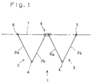
- a folding door 1 which is formed from two pairs of wings 2, 3.
- the two wing pairs 2, 3 each consist of wings 2a, 2b and 3a, 3b.
- the two wings 2a, 2b and 3a, 3b are each articulated to one another via hinges 4.
- the two wings 2b, 3a of the two adjoining wing pairs 2, 3 are connected to one another in an articulated manner by a fitting 6 and are guided in a hanging manner in an upper guide rail 7.
- the other ends of the outer wings 2a and 3b are also provided with fittings 5 with which they in the overhead guide rail 7 are slidably guided.
- the fitting 6 for connecting the two wings 2b, 3a of the two pairs of wings 2, 3 has the effect that, if, for example, the wing 3b is pulled by hand in the opening direction, also for moving the two wing pairs 2, 3 into the open position a force is exerted on the wing 2b of the first pair of wings 2b in the opening direction.
- a force is exerted on the wing 2b of the first pair of wings 2b in the opening direction.
- an opening force is exerted on the wing 2a of the first pair of wings 2.
- the wing 3a of the second pair of wings 3 is acted upon in the direction of rotation for pivoting into the open position.
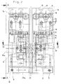
- the structure and parts of the fitting 6 are shown in more detail in Figures 2 to 7 and described below using the same.
- the fitting 6 is constructed from two supports 8, which are designed symmetrically with respect to the pivot axis.
- the two supports 8 are firmly connected to one another by a tab 10 screwed to them by screws 9.
- each support plates 11 can be screwed on by means of screws 12 which are passed through an elongated hole in the support 8 and engage in a threaded bore of the support plates 11.
- the support plates 11 carry the spaced support rollers 13, which are guided in the inner contour of the guide rail 7.
- the door leaves 3a, 2b are held on the carrier 8 via hinges 17 on a flange plate, to which the other leg 19 of the hinge 17 is fastened.
- the height is adjusted by means of an adjusting screw 15 which engages through a threaded hole in a bent tab 14 of the support plate 11 and is supported with its end against a web 16 of the carrier 8.
- the idlers 13 have horizontal axes of rotation.
- the guide rollers 19 have vertical axes of rotation and are attached to a slide 20 which is adjustable in the vertical direction relative to the support rollers 13.
- the slide has two elongated holes 21 which are arranged at a parallel distance from one another and which are penetrated by fastening screws 22 which can each be screwed into threaded holes in the support plates 11 and which serve to clamp the slide 20 opposite the support plate 11.
- the hinges 17 are recessed in a blind bore 23 which extends from the inner surface 24 of the wing 3 and are screwed by means of screws, not shown.
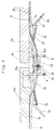
- drivers 25, 25a and drawing wedges 26, 26a are attached in the area of each of the hinges 17 arranged at a height from one another.
- the driver 25 is fixed in the wing 2b on its inner surface 24 by screws.
- the driver 25a is fastened to the inner surface 24 of the wing 3a by screws.
- the pull wedge 26a is assigned to this driver 25a.
- the two pulling wedges 26, 26a are passed through openings in the respective supports 8.
- the design of the pulling wedges 26, 26a can be seen from FIGS. 6 and 7. Starting from the end 27, which faces the driver 26, 26a, the drawing wedge 26, 26a is divided into two arms 28, 29 which are at an angle to one another and form two wedge surfaces 30, 31 which extend apart.
- the driver-side end 27 is provided with a recess 32 for threading and mounting the drawing wedge 26, 26a on the driver 25, 25a. Furthermore, it has a pivot pin 33, which with a like a snap hook formed end of the associated driver 25, 25a can be brought into engagement. As can be seen in relation to the driver 25a from FIG. 4, this has a tongue 34 which can spring back into an elongated hole 35 so that the pivot pin 33 can be inserted into the elongated hole 35. Then the tongue 34 springs back. The pivot pin 33 and thus the pull wedge 26, 26a is guided in the slot 35 via the pivot pin 33 and coupled to the driver 25, 25a. The closed position of the folding door 1 is shown in FIG.
- the driver 25a carries the pull wedge 26a, which is guided through a recess in the carrier 8 and at the end protrudes from a guide channel which contains a sliding surface 36.
- the two arms 28, 29 are with their wedge surfaces 30, 31 only in loose or no contact with the associated sliding surface 36, 37 which is on the carrier 8 or on the inner surface 24 of the wings 2b, 3a or in the direction of the above Guide part of the driver to which the respective pull wedge 26 or 26a is not fastened, the pair of door leaves 3 are present.
- the wing 3a is pivoted by hand about the hinge axis of the hinges 17.
- the driver 25a likewise measures a swivel path and, after measuring the play of the elongated hole in the driver, acts by pulling on the pulling wedge 26a via the swivel pin 33.
- This is drawn with its arms 28, 29 located at the other end into the gap between the inner surface 24 of the wing 2b or the sliding surface 37 of the driver 25 and the sliding surface 36 of the carrier 8.
- its wedge surfaces 30, 31 are supported on the inner surface 24 or the sliding surfaces 37, 36 of the door leaf 2b or driver 25 and carrier 8, so that on the leaf 2b a force in the sense of pivoting into the open position about the hinge axis of the Hinges 17 is exercised.
- This Swiveling facilitates the further unfolding of the adjoining wing 2a and following, so that the front surface can be opened.
- the operator would exert pressure on the wing 2b in the position shown in FIG. 5 when the position was partially open, this would not result in damage or tearing of the hinges 17 because the wedge surfaces 30, 31 were components of one another are spaced arms 28, 29 which can spring towards each other under pressure.
- a tensile force is exerted on the pulling wedge 26 via the driver 25, which engages on the one hand on the stationary sliding surface 36 with its wedge surface 30 and on the other hand on the sliding surface 37 or Inner surface 24 of the wing 3a and exerts a force in the opening direction on this wing.
- the resilient arms 28, 29 help to pull the wings back into the position in which they are in a plane once a certain position has been reached.
- the invention is also applicable to folding doors with more than two pairs of wings. When unfolding on the wing doors of the following adjacent wing pairs, a moment is progressively exerted in the opening direction.
Landscapes
- Engineering & Computer Science (AREA)
- Civil Engineering (AREA)
- Structural Engineering (AREA)
- Mechanical Engineering (AREA)
- Extensible Doors And Revolving Doors (AREA)
- Support Devices For Sliding Doors (AREA)
Abstract
Description
- Die Erfindung betrifft einen Beschlag für die Verbindung der Flügelpaare einer mehrere Flügelpaare aufweisenden Falttür, deren einzelne Flügel gelenkig miteinander verbunden sind, wobei im Scharnierbereich zweier benachbarter Flügel zweier aneinandergrenzender Flügelpaare mindestens am Flügel des einen Flügelpaares ein Mitnehmer angebracht ist, der auf eine Betätigungsvorrichtung einwirkt, die bei Verschwenken des mit dem Mitnehmer versehenen Flügels auf den im Scharnierbereich benachbarten Flügel des anderen Flügelpaares ein Drehmoment im Öffnungssinne ausübt.
- Ein solcher Beschlag ist beispielsweise aus dem DE GM 88 09 497 bekannt. Dabei sind jeweils doppelarmige Rollenhebel vorgesehen, deren einer Hebel je nach Betätigung eines der beiden Flügel von einem Mitnehmer beaufschlagt wird und der die Betätigungskraft auf den anderen Flügel im Öffnungssinne überträgt. Um die gewünschten Öffnungswege erreichen zu können, müssen die Betätigungshebel jeweils eine bestimmte Länge aufweisen. Aufgrund der Ausbildung als doppelarmiger Winkelhebel ist eine große Bautiefe erforderlich. Diese ist bezüglich des dahinterliegenden, zu nutzenden Raumes störend.
- Der Erfindung liegt die Aufgabe zugrunde, einen Beschlag für Falttüren zu schaffen, der einfach im Aufbau ist und nur eine geringe Bautiefe benötigt.
- Diese Aufgabe wird erfindungsgemäß dadurch gelöst, daß die Betätigungsvorrichtung einen Ziehkeil umfaßt, der mit einem Ende am Mitnehmer um eine zur Scharnierachse der Flügelpaare parallele Achse verschwenkbar angelenkt ist und der an seinem anderen Ende mit auseinander verlaufenden Keilflächen versehen ist, von denen sich die eine an einer Gleitfläche des Flügels und die andere an der Gleitfläche eines Trägers bei ziehender Einwirkung des Mitnehmers abstützt.
- Von Vorteil ist ferner, daß nur wenige und einfach herstellbare Bauteile benutzt werden können. Der Ziehkeil ist einfach herzustellen und auch auf Dauer funktionsfähig. Da die Teile ohne weiteres aus Kunststoff hergestellt werden können, bedarf es auch keiner besonderen Wartung.
- Ein weiterer Vorteil besteht darin, daß die Träger auch ohne die Verwendung der Ziehkeile und Mitnehmer eingesetzt werden können, so daß für sämtliche Anlenkstellen der einzelnen Flügel der Falttüre an der Führungsschiene die gleichen Grundelemente benutzt werden können.
- In weiterer Ausgestaltung der Erfindung ist vorgesehen, daß die Keilflächen parallel zur Schwenkachse verlaufen. Bevorzugt ist der Ziehkeil als Kunststoffteil ausgebildet und die Keilflächen sind Bestandteil zweier am Ende angeordneter, auseinanderverlaufender Arme. Hierbei wird ein wesentlicher Vorteil insofern erreicht, als beim unbeabsichtigten Schließen der Türe, ausgehend vom teilweise geöffneten Zustand, die beiden Arme des Ziehkeiles aufeinanderzu federn können, ohne daß wesentliche Kräfte auf die Anbringung der Scharniere ausgeübt werden. Hierdurch wird ein Ausbrechen der Scharniere vermieden. Die Lebensdauer der Verbindung wird also günstig beeinflußt.
- Zur Erleichterung der Montage ist vorgesehen, daß das am Mitnehmer angelenkte Ende des Ziehkeils eine Schwenkachse mit anschließender Ausnehmung aufweist und der Mitnehmer mit einem karabinerhakenartigen Verschluß und einem Langloch versehen ist. Bevorzugt ist auch der Mitnehmer als Kunststoffspritzgußteil ausgebildet.
- Um den Träger gleichzeitig für die Anbringung der Trag- und Führungsrollen nutzen zu können, ist dieser mit entsprechenden Bohrungen und Verstelleinrichtungen versehen. Die Trag- und Führungsrollen sind über separate Tragplatten bzw. Schieber an den Träger anschließbar.
- Bevorzugt sind für eine Falttüre, die zwei Flügelpaare aufweist und die frei in beide Schieberichtungen öffenbar ist, vorgesehen, daß die Flügel der aneinandergrenzenden Flügelpaare je einen Träger und Mitnehmer sowie Ziehkeile aufweisen. Der Mitnehmer des einen Flügels weist vorzugsweise einen Teil der Gleitfläche für den dem Mitnehmer des anderen Flügels zugeordneten Ziehkeil auf.
- Um eine starre Verbindung herstellen zu können, sind die Träger miteinander über ein Koppelelement verbunden.
- Es zeigt
- Figur 1
- schematisch eine Draufsicht auf eine Anordnung mit zwei Flügeltürpaaren,
- Figur 2
- eine Rückansicht auf die Falttür und zwar bezüglich der Darstellung des Beschlages zur Führung zweier aneinandergrenzender Flügelpaare,
- Figur 3
- einen Schnitt A-A gemäß Figur 2,
- Figur 4
- einen Schnitt B-B gemäß Figur 2 bei geschlossener Falttür,
- Figur 5
- einen Öffnungsvorgang, nachdem eines der Flügelpaare von Hand verschwenkt wurde,
- Figur 6
- den Ziehkeil als Einzelteil, teilweise geschnitten und
- Figur 7
- eine Draufsicht zu Figur 6.
- In Figur 1 ist eine Falttür 1 dargestellt, die aus zwei Flügelpaaren 2, 3 gebildet ist. Die beiden Flügelpaare 2, 3 bestehen jeweils aus Flügeln 2a, 2b und 3a, 3b. Die beiden Flügel 2a, 2b und 3a, 3b sind jeweils über Scharniere 4 gelenkig miteinander verbunden. Die beiden Flügel 2b, 3a der beiden aneinandergrenzenden Flügelpaare 2, 3 sind durch einen Beschlag 6 gelenkig miteinander verbunden und in einer oberen Führungsschiene 7 hängend geführt. Die anderen Enden der außenliegenden Flügel 2a und 3b sind ebenfalls mit Beschlägen 5 versehen, mit denen sie in der obenliegenden Führungsschiene 7 verschiebbar geführt sind. Der Beschlag 6 zur Verbindung der beiden Flügel 2b, 3a der beiden Fügelpaare 2, 3 bewirkt, daß dann, wenn beispielsweise auf den Flügel 3b ziehend im Öffnungssinne von Hand eingewirkt wird, auch für das Verschieben der beiden Flügelpaare 2, 3 in die geöffnete Stellung eine Kraft im Öffnungssinne auf den Flügel 2b des ersten Flügelpaare 2b ausgeübt wird. Gleiches gilt umgekehrt, wenn auf den Flügel 2a des ersten Flügelpaares 2 eine Öffnungskraft ausgeübt wird. In diesem Falle wird der Flügel 3a des zweiten Flügelpaares 3 im Drehsinne zur Verschwenkung in die geöffnete Stellung hinein beaufschlagt. Der Aufbau und Teile des Beschlages 6 sind in den Figuren 2 bis 7 näher dargestellt und an Hand derselben nachfolgend beschrieben. Zur Vereinfachung der Werkzeuge und der Ausbildung der Teile ist der Beschlag 6 aus zwei Trägern 8 aufgebaut, die bezüglich der Schwenkachse symmetrisch gestaltet sind. Die beiden Träger 8 sind durch eine an ihnen durch Schrauben 9 angeschraubte Lasche 10 fest miteinander verbunden. Am oberen Ende der beiden Träger 8 sind jeweils Tragplatten 11 über Schrauben 12, die durch ein Langloch im Träger 8 hindurchgeführt sind und in eine Gewindebohrung der Tragplatten 11 eingreifen, anschraubbar. Die Tragplatten 11 tragen die beabstandeten Tragrollen 13, die in der Innenkontur der Führungsschiene 7 geführt sind. Die Türflügel 3a, 2b sind über Scharniere 17 an einer Flanschplatte, an der der andere Schenkel 19 des Scharniers 17 befestigt ist, am Träger 8 gehalten. Die Höheneinstellung erfolgt über eine Stellschraube 15, die eine Gewindebohrung in einem abgebogenen Lappen 14 der Tragplatte 11 durchgreift und sich mit ihrem Ende gegen einen Steg 16 des Trägers 8 abstützt. Die Tragrollen 13 haben horizontale Drehachsen. Zusätzlich sind weitere im Abstand voneinander angeordnete Führungsrollen 19 vorhanden, die ebenfalls in die Führungsschiene 7 eingreifen und ein Kippen der Türen verhindern sollen. Die Führungsrollen 19 haben vertikal verlaufende Drehachsen und sind an einem Schieber 20 befestigt, der in Vertikalrichtung gegenüber den Tragrollen 13 verstellbar ist. Der Schieber weist zwei im parallelen Abstand zueinander angeordnete Langlöcher 21 auf, welche von Befestigungsschrauben 22 durchgriffen werden, die jeweils in Gewindebohrungen der Tragplatten 11 einschraubbar sind und zum Festklemmen des Schiebers 20 der Tragplatte 11 gegenüber dienen. Die Scharniere 17 sind in einer Sackbohrung 23, die von der Innenfläche 24 des Flügels 3 ausgeht, versenkt aufgenommen und über nicht dargestellte Schrauben verschraubt. Es sind zwei im Höhenabstand zueinander angeordnete Scharniere 17 vorhanden. Es ist aus Figur 2 erkennbar, daß jeder der beiden Träger 8 mit zwei solcher Scharniere 17 versehen ist.
- Im Bereich jeweils der im Höhenabstand zueinander angeordneten Scharniere 17 sind Mitnehmer 25, 25a und Ziehkeile 26, 26a angebracht. Der Mitnehmer 25 ist im Flügel 2b an dessen Innenfläche 24 durch Schrauben befestigt. Der Mitnehmer 25a ist an der Innenfläche 24 des Flügels 3a durch Schrauben befestigt. Diesen Mitnehmer 25a ist der Ziehkeil 26a zugeordnet. Die beiden Ziehkeile 26, 26a sind durch Öffnungen der jeweiligen Träger 8 hindurchgeführt. Aus den Figuren 6 und 7 ist die Gestaltung der Ziehkeile 26, 26a ersichtlich. Ausgehend von dem Ende 27, das dem Mitnehmer 26, 26a zugewandt ist, teilt sich der Ziehkeil 26, 26a in zwei Arme 28, 29, die im Winkel zueinander stehen und zwei auseinanderverlaufende Keilflächen 30, 31 bilden. Das mitnehmerseitige Ende 27 ist mit einer Ausnehmung 32 zum Einfädeln und Montieren des Ziehkeiles 26, 26a am Mitnehmer 25, 25a versehen. Ferner weist er einen Schwenkzapfen 33 auf, der mit einem wie ein Karabinerhaken ausgebildetes Ende des zugehörigen Mitnehmers 25, 25a in Eingriff bringbar ist. Wie in Bezug auf den Mitnehmer 25a aus Figur 4 erkennbar, besitzt dieser eine Zunge 34, welche in ein Langloch 35 zurückfedern kann, so daß der Schwenkzapfen 33 in das Langloch 35 eingeführt werden kann. Anschließend federt die Zunge 34 zurück. Der Schwenkzapfen 33 und damit der Ziehkeil 26, 26a ist im Langloch 35 über den Schwenkzapfen 33 geführt an den Mitnehmer 25, 25a angekoppelt. In Figur 4 ist die geschlossene Position der Falttür 1 dargestellt. Es sind nur Teile der aneinandergrenzenden Flügel 2b und 3a der benachbarten Flügelpaare 2, 3 ersichtlich. Es ist erkennbar, daß der Mitnehmer 25a den Ziehkeil 26a trägt, welcher durch eine Ausnehmung im Träger 8 hindurchgeführt ist und am Ende aus einem Führungskanal, der eine Gleitfläche 36 enthält, herausragt. Die beiden Arme 28, 29 sind mit ihren Keilflächen 30, 31 nur im losen bzw. gar keinen Kontakt zu der zugeordneten Gleitfläche 36, 37, welche am Träger 8 bzw. an der Innenfläche 24 der Flügel 2b, 3a oder in Richtung auf den vorstehenden Führungsteil des Mitnehmers an welchen der jeweilige Ziehkeil 26 oder 26a nicht befestigt ist, des Türflügelpaares 3 vorhanden sind. Von Hand wird der Flügel 3a um die Gelenkachse der Scharniere 17 verschwenkt. Dabei durchmißt der Mitnehmer 25a ebenfalls einen Schwenkweg und wirkt nach Durchmessen des Spiels des Langloches im Mitnehmer über den Schwenkzapfen 33 ziehend auf den Ziehkeil 26a ein. Dieser wird mit seinen am anderen Ende befindlichen Armen 28, 29 in den Spalt zwischen der Innenfläche 24 des Flügels 2b bzw. der Gleitfläche 37 des Mitnehmers 25 und der Gleitfläche 36 des Trägers 8 hineingezogen. Dabei stützen sich seine Keilflächen 30, 31 an der Innenfläche 24 bzw. den Gleitflächen 37, 36 von Türflügel 2b bzw. Mitnehmer 25 und Träger 8 ab, so daß auf den Flügel 2b eine Kraft im Sinne des Verschwenkens in die Öffnungsposition um die Gelenkachse der Scharniere 17 ausgeübt wird. Dieses Verschwenken erleichtert das weitere Auffalten des daran anschließenden Flügels 2a und folgende, so daß die Frontfläche geöffnet werden kann. Für den Fall, daß bei teilweise geöffneter Position die Bedienungsperson einen Druck auf den Flügel 2b in der in Figur 5 gezeigten Stellung ausüben würde, so hat dies keine Beschädigung oder ein Herausreißen der Scharniere 17 zur Folge, weil die Keilflächen 30, 31 Bestandteile von zueinander beabstandeten Armen 28, 29 sind, die unter dem Druck aufeinanderzu federn können.
- Für den Fall, daß im Öffnungssinne eine Kraft auf den Flügel 2b ausgeübt wird, wird eine Zugkraft über den Mitnehmer 25 auf den Ziehkeil 26 ausgeübt, dieser legt sich einerseits an die ortsfeste Gleitfläche 36 mit seiner Keilfläche 30 und andererseits an die Gleitfläche 37 bzw. Innenfläche 24 des Flügels 3a an und übt eine Kraft im Öffnungssinne auf diesen Flügel aus. Bei einem Überführen der Flügel 2b und 3a von der geöffneten Position in die geschlossene Postition helfen ab Erreichen einer bestimmten Position die zurückfedernden Arme 28, 29 mit, die Flügel in die Position in der sie in einer Ebene liegen, zurückzuziehen.
- Die Erfindung ist auch auf Falttüren mit mehr als zwei Flügelpaaren anwendbar. Wobei beim Auffalten auf die Flügeltüren der folgenden jeweils aneinandergrenzenden Flügelpaare ein Moment im Öffnungssinne fortschreitend ausgeübt wird.
-
- 1
- Falttür
- 2,3
- Flügelpaare
- 2a,2b; 3a, 3b
- Flügel
- 4
- Scharnier
- 5
- Beschlag
- 6
- Beschlag für die Verbindung der Flügelpaare
- 7
- Führungsschiene
- 8
- Träger
- 9
- Schrauben
- 10
- Lasche
- 11
- Tragplatte
- 12
- Schrauben
- 13
- Tragrollen
- 14
- Lappen
- 15
- Stellschraube
- 16
- Steg
- 17
- Scharnier
- 18
- Flanschplatte
- 19
- Führungsrolle
- 20
- Schieber
- 21
- Langloch
- 22
- Befestigungsschrauben
- 23
- Sackbohrung
- 24
- Innenfläche
- 25,25a
- Mitnehmer
- 26, 26a
- Ziehkeil
- 27
- mitnehmerseitiges Ende des Ziehkeils
- 28, 29
- Arme
- 30, 31
- Keilfläche
- 32
- Ausnehmung
- 33
- Schwenkzapfen
- 34
- Zunge
- 35
- Langloch
- 36, 37
- Gleitflächen
Claims (8)
- Beschlag für die Verbindung der Flügelpaare einer mehrere Flügelpaare aufweisenden Falttür, deren einzelne Flügel gelenkig miteinander verbunden sind, wobei im Scharnierbereich zweier benachbarter Flügel zweier aneinandergrenzender Flügelpaare mindestens am Flügel des einen Flügelpaares ein Mitnehmer angebracht ist, der auf eine Betätigungsvorrichtung einwirkt, die bei Verschwenken des mit dem Mitnehmer versehenen Flügels auf den im Scharnierbereich benachbarten Flügel des anderen Flügelpaares ein Drehmoment im Öffnungssinne ausübt,
dadurch gekennzeichnet,
daß die Betätigungsvorrichtung einen Ziehkeil (26, 26a) umfaßt, der mit einem Ende (27) am Mitnehmer (25, 25a) um eine zur Scharnierachse der Flügelpaare (2, 3) parallele Achse (33) verschwenkbar angelenkt ist und der an seinem anderen Ende mit auseinander verlaufenden Keilflächen (30, 31) versehen ist, von denen sich die eine an einer Gleitfläche (24, 37) des Flügels (2b, 3a) und die andere an der Gleitfläche (36) eines Trägers (8) bei ziehender Einwirkung des Mitnehmers (25, 25a) abstützt. - Beschlag nach Anspruch 1,
dadurch gekennzeichnet,
daß die Keilflächen (30, 31) parallel zur Schwenkachse (33) verlaufen. - Beschlag nach Anspruch 1,
dadurch gekennzeichnet,
daß der Ziehkeil (26, 26a) als Kunststoffteil ausgebildet ist und die Keilflächen (30, 31) Bestandteil zweier am Ende angeordneter, auseinander verlaufender Arme (28, 29) sind. - Beschlag nach Anspruch 1,
dadurch gekennzeichnet,
daß das am Mitnehmer (25, 25a) angelenkte Ende (27) des Ziehkeils (26, 26a) eine Schwenkachse (33) mit anschließender Ausnehmung (32) aufweist und der Mitnehmer (25, 25a) mit einem karabinerhakenartigen Verschluß (34) und einem Langloch (35) versehen ist. - Beschlag nach Anspruch 4,
dadurch gekennzeichnet,
daß der Mitnehmer (25, 25a) als Kunststoffspritzgußteil ausgebildet ist. - Beschlag nach Anspruch 1,
dadurch gekennzeichnet,
daß der Träger (8) zur Befestigung und Führung der beiden Flügel (2b, 3a) der aneinandergrenzenden Flügelpaare (2, 3) der Falttür (1) durch Trag- und Führungsrollen (13, 19) an einer Führungsschiene (7)ausgebildet ist. - Beschlag nach einem oder mehreren der Ansprüche 1 bis 6,
dadurch gekennzeichnet,
daß für die Flügel (2b, 3a) der aneinandergrenzenden Flügelpaare (2, 3) je ein Träger (8) und Mitnehmer (25, 25a) sowie Ziehkeil (26, 26a) vorhanden ist und daß der Mitnehmer (25, 25a) des einen Flügels (2b, 3a) die Gleitfläche (37) für den dem Mitnehmer (25, 25a) des anderen Flügels (3a, 2b) zugeordneten Ziehkeil (26a, 26) aufweist. - Beschlag nach Anspruch 7,
dadurch gekennzeichnet,
daß die Träger (8) miteinander über Koppelelemente (10) verbunden sind.
Priority Applications (1)
| Application Number | Priority Date | Filing Date | Title |
|---|---|---|---|
| AT91114409T ATE95879T1 (de) | 1990-09-11 | 1991-08-28 | Beschlag fuer eine falttuer mit mehreren fluegelpaaren. |
Applications Claiming Priority (2)
| Application Number | Priority Date | Filing Date | Title |
|---|---|---|---|
| DE4028760A DE4028760A1 (de) | 1990-09-11 | 1990-09-11 | Beschlag fuer eine falttuer mit mehreren fluegelpaaren |
| DE4028760 | 1990-09-11 |
Publications (2)
| Publication Number | Publication Date |
|---|---|
| EP0475193A1 true EP0475193A1 (de) | 1992-03-18 |
| EP0475193B1 EP0475193B1 (de) | 1993-10-13 |
Family
ID=6414003
Family Applications (1)
| Application Number | Title | Priority Date | Filing Date |
|---|---|---|---|
| EP91114409A Expired - Lifetime EP0475193B1 (de) | 1990-09-11 | 1991-08-28 | Beschlag für eine Falttür mit mehreren Flügelpaaren |
Country Status (4)
| Country | Link |
|---|---|
| EP (1) | EP0475193B1 (de) |
| AT (1) | ATE95879T1 (de) |
| DE (1) | DE4028760A1 (de) |
| ES (1) | ES2046836T3 (de) |
Cited By (2)
| Publication number | Priority date | Publication date | Assignee | Title |
|---|---|---|---|---|
| FR2704269A1 (fr) * | 1993-04-21 | 1994-10-28 | Hettich Paul Gmbh & Co | Ferrure pour porte coulissante et pliante. |
| CN108166899A (zh) * | 2018-02-09 | 2018-06-15 | 广东东泰五金精密制造有限公司 | 一种家具折叠门的调节机构 |
Families Citing this family (1)
| Publication number | Priority date | Publication date | Assignee | Title |
|---|---|---|---|---|
| DE4329739A1 (de) * | 1993-09-03 | 1995-03-09 | Holzaepfel Christian Gmbh | Türanordnung, insbesondere für Möbel, mit Faltschiebetür |
Citations (4)
| Publication number | Priority date | Publication date | Assignee | Title |
|---|---|---|---|---|
| DE1759226A1 (de) * | 1967-04-12 | 1971-06-03 | Bator Ag | Falttor |
| DE2506469A1 (de) * | 1974-02-13 | 1975-08-14 | Gunfred Ag Ab | Vorrichtung an zusammenfaltbaren trennwaenden |
| DE3507863A1 (de) * | 1985-03-06 | 1986-09-11 | Paul Hettich GmbH & Co, 4983 Kirchlengern | Falttuer |
| DE8809497U1 (de) * | 1988-07-26 | 1989-11-23 | Paul Hettich GmbH & Co, 4983 Kirchlengern | Falttür mit mehreren Flügelpaaren |
Family Cites Families (1)
| Publication number | Priority date | Publication date | Assignee | Title |
|---|---|---|---|---|
| NL190790C (nl) * | 1980-04-15 | 1994-08-16 | Pella Bv | Vouwwand. |
-
1990
- 1990-09-11 DE DE4028760A patent/DE4028760A1/de active Granted
-
1991
- 1991-08-28 AT AT91114409T patent/ATE95879T1/de active
- 1991-08-28 EP EP91114409A patent/EP0475193B1/de not_active Expired - Lifetime
- 1991-08-28 ES ES199191114409T patent/ES2046836T3/es not_active Expired - Lifetime
Patent Citations (4)
| Publication number | Priority date | Publication date | Assignee | Title |
|---|---|---|---|---|
| DE1759226A1 (de) * | 1967-04-12 | 1971-06-03 | Bator Ag | Falttor |
| DE2506469A1 (de) * | 1974-02-13 | 1975-08-14 | Gunfred Ag Ab | Vorrichtung an zusammenfaltbaren trennwaenden |
| DE3507863A1 (de) * | 1985-03-06 | 1986-09-11 | Paul Hettich GmbH & Co, 4983 Kirchlengern | Falttuer |
| DE8809497U1 (de) * | 1988-07-26 | 1989-11-23 | Paul Hettich GmbH & Co, 4983 Kirchlengern | Falttür mit mehreren Flügelpaaren |
Cited By (2)
| Publication number | Priority date | Publication date | Assignee | Title |
|---|---|---|---|---|
| FR2704269A1 (fr) * | 1993-04-21 | 1994-10-28 | Hettich Paul Gmbh & Co | Ferrure pour porte coulissante et pliante. |
| CN108166899A (zh) * | 2018-02-09 | 2018-06-15 | 广东东泰五金精密制造有限公司 | 一种家具折叠门的调节机构 |
Also Published As
| Publication number | Publication date |
|---|---|
| DE4028760A1 (de) | 1992-03-12 |
| ES2046836T3 (es) | 1994-02-01 |
| DE4028760C2 (de) | 1992-07-02 |
| ATE95879T1 (de) | 1993-10-15 |
| EP0475193B1 (de) | 1993-10-13 |
Similar Documents
| Publication | Publication Date | Title |
|---|---|---|
| DE68914595T2 (de) | Türscharnier mit Schnellkupplung. | |
| EP1959080B1 (de) | Beschlag für einen Schiebeflügel von Fenster oder Tür | |
| EP0065109B1 (de) | Scharnier | |
| AT519903B1 (de) | Schiene zur Führung eines Schlittens einer Möbeltüre | |
| EP0598364B1 (de) | Band für Türen, Fenster und dergleichen | |
| DE3805475A1 (de) | Vorrichtung zur walzgutfuehrung zwischen den walzen eines walzgeruestes | |
| EP0478639B1 (de) | Scharnier | |
| EP3201413B1 (de) | Beschlaganordnung | |
| DE3904210C2 (de) | ||
| EP0475193B1 (de) | Beschlag für eine Falttür mit mehreren Flügelpaaren | |
| DE2261946A1 (de) | Beschlag fuer aus metall- oder kunststoffprofilen gefertigte fenster und tueren od.dgl | |
| EP0255598A2 (de) | Kassenlade | |
| EP0790375B1 (de) | Fenster oder Fenstertür mit Drehflügel-oder Drehkippflügel-Beschlag | |
| DE19806727A1 (de) | Fenster- oder Türverschluß | |
| DE2507910B2 (de) | Fehlbedienungssicherung für das Betätigungsgestänge eines Dreh-Kipp-Fensters | |
| DE19605784C2 (de) | Fenster oder Fenstertüre mit Drehflügel- oder Drehkippflügelbeschlag | |
| EP0279274A2 (de) | Lamellenladen für Fenster oder Türen | |
| EP0246431A2 (de) | Ausstellvorrichtung für Kippflügel, insbesondere Drehkipp- oder auch Schiebekippflügel, von Fenstern, Türen od. dgl. | |
| DE2443036A1 (de) | Ausstellvorrichtung | |
| DE9101597U1 (de) | Scharnier | |
| DE3916348C2 (de) | ||
| EP1259691B1 (de) | Auflaufbock | |
| EP0429981B1 (de) | Verdeckt im Falz angeordneter Beschlag für Kipp-Schwenk-flügelfenster oder -türen, insb. mit Holzrahmen | |
| DE102004015427B4 (de) | Sicherheitsbeschlag | |
| DE516628C (de) | In Fuehrungsrinnen verschiebbares Schiebefenster |
Legal Events
| Date | Code | Title | Description |
|---|---|---|---|
| PUAI | Public reference made under article 153(3) epc to a published international application that has entered the european phase |
Free format text: ORIGINAL CODE: 0009012 |
|
| AK | Designated contracting states |
Kind code of ref document: A1 Designated state(s): AT BE DE ES FR GB IT |
|
| 17P | Request for examination filed |
Effective date: 19920205 |
|
| RTI1 | Title (correction) | ||
| 17Q | First examination report despatched |
Effective date: 19920727 |
|
| RBV | Designated contracting states (corrected) |
Designated state(s): AT BE ES FR GB IT |
|
| REG | Reference to a national code |
Ref country code: DE Ref legal event code: 8566 |
|
| GRAA | (expected) grant |
Free format text: ORIGINAL CODE: 0009210 |
|
| AK | Designated contracting states |
Kind code of ref document: B1 Designated state(s): AT BE ES FR GB IT |
|
| REF | Corresponds to: |
Ref document number: 95879 Country of ref document: AT Date of ref document: 19931015 Kind code of ref document: T |
|
| ITF | It: translation for a ep patent filed | ||
| GBT | Gb: translation of ep patent filed (gb section 77(6)(a)/1977) |
Effective date: 19931123 |
|
| REG | Reference to a national code |
Ref country code: ES Ref legal event code: FG2A Ref document number: 2046836 Country of ref document: ES Kind code of ref document: T3 |
|
| ET | Fr: translation filed | ||
| PLBE | No opposition filed within time limit |
Free format text: ORIGINAL CODE: 0009261 |
|
| STAA | Information on the status of an ep patent application or granted ep patent |
Free format text: STATUS: NO OPPOSITION FILED WITHIN TIME LIMIT |
|
| 26N | No opposition filed | ||
| PGFP | Annual fee paid to national office [announced via postgrant information from national office to epo] |
Ref country code: GB Payment date: 19950809 Year of fee payment: 5 |
|
| PGFP | Annual fee paid to national office [announced via postgrant information from national office to epo] |
Ref country code: FR Payment date: 19960810 Year of fee payment: 6 |
|
| PGFP | Annual fee paid to national office [announced via postgrant information from national office to epo] |
Ref country code: BE Payment date: 19960822 Year of fee payment: 6 Ref country code: AT Payment date: 19960822 Year of fee payment: 6 |
|
| PG25 | Lapsed in a contracting state [announced via postgrant information from national office to epo] |
Ref country code: GB Effective date: 19960828 |
|
| PGFP | Annual fee paid to national office [announced via postgrant information from national office to epo] |
Ref country code: ES Payment date: 19960830 Year of fee payment: 6 |
|
| GBPC | Gb: european patent ceased through non-payment of renewal fee |
Effective date: 19960828 |
|
| PG25 | Lapsed in a contracting state [announced via postgrant information from national office to epo] |
Ref country code: AT Free format text: LAPSE BECAUSE OF NON-PAYMENT OF DUE FEES Effective date: 19970828 |
|
| PG25 | Lapsed in a contracting state [announced via postgrant information from national office to epo] |
Ref country code: ES Free format text: LAPSE BECAUSE OF THE APPLICANT RENOUNCES Effective date: 19970829 |
|
| PG25 | Lapsed in a contracting state [announced via postgrant information from national office to epo] |
Ref country code: BE Free format text: LAPSE BECAUSE OF NON-PAYMENT OF DUE FEES Effective date: 19970831 |
|
| BERE | Be: lapsed |
Owner name: HUWIL-WERKE G.M.B.H. MOBELSCHLOSS- U. BESCHLAGFAB Effective date: 19970831 |
|
| PG25 | Lapsed in a contracting state [announced via postgrant information from national office to epo] |
Ref country code: FR Free format text: LAPSE BECAUSE OF NON-PAYMENT OF DUE FEES Effective date: 19980430 |
|
| REG | Reference to a national code |
Ref country code: FR Ref legal event code: ST |
|
| REG | Reference to a national code |
Ref country code: ES Ref legal event code: FD2A Effective date: 20001009 |
|
| PG25 | Lapsed in a contracting state [announced via postgrant information from national office to epo] |
Ref country code: IT Free format text: LAPSE BECAUSE OF NON-PAYMENT OF DUE FEES Effective date: 20050828 |