EP0475329B1 - Schaufelgitter für Turbomaschinen mit Saugschlitzen - Google Patents
Schaufelgitter für Turbomaschinen mit Saugschlitzen Download PDFInfo
- Publication number
- EP0475329B1 EP0475329B1 EP91115218A EP91115218A EP0475329B1 EP 0475329 B1 EP0475329 B1 EP 0475329B1 EP 91115218 A EP91115218 A EP 91115218A EP 91115218 A EP91115218 A EP 91115218A EP 0475329 B1 EP0475329 B1 EP 0475329B1
- Authority
- EP
- European Patent Office
- Prior art keywords
- blade
- wall
- port
- blades
- neck
- Prior art date
- Legal status (The legal status is an assumption and is not a legal conclusion. Google has not performed a legal analysis and makes no representation as to the accuracy of the status listed.)
- Expired - Lifetime
Links
- 238000007789 sealing Methods 0.000 claims description 4
- 238000012856 packing Methods 0.000 claims 5
- FNYLWPVRPXGIIP-UHFFFAOYSA-N Triamterene Chemical compound NC1=NC2=NC(N)=NC(N)=C2N=C1C1=CC=CC=C1 FNYLWPVRPXGIIP-UHFFFAOYSA-N 0.000 claims 3
- 238000003491 array Methods 0.000 claims 2
- 238000007599 discharging Methods 0.000 claims 1
- 239000012530 fluid Substances 0.000 description 6
- 230000007423 decrease Effects 0.000 description 3
- 230000000694 effects Effects 0.000 description 2
- 230000003068 static effect Effects 0.000 description 2
- 238000004891 communication Methods 0.000 description 1
- 238000005259 measurement Methods 0.000 description 1
- 238000000034 method Methods 0.000 description 1
- 210000003462 vein Anatomy 0.000 description 1
Images


Classifications
-
- F—MECHANICAL ENGINEERING; LIGHTING; HEATING; WEAPONS; BLASTING
- F01—MACHINES OR ENGINES IN GENERAL; ENGINE PLANTS IN GENERAL; STEAM ENGINES
- F01D—NON-POSITIVE DISPLACEMENT MACHINES OR ENGINES, e.g. STEAM TURBINES
- F01D5/00—Blades; Blade-carrying members; Heating, heat-insulating, cooling or antivibration means on the blades or the members
- F01D5/12—Blades
- F01D5/14—Form or construction
- F01D5/141—Shape, i.e. outer, aerodynamic form
- F01D5/145—Means for influencing boundary layers or secondary circulations
-
- F—MECHANICAL ENGINEERING; LIGHTING; HEATING; WEAPONS; BLASTING
- F04—POSITIVE - DISPLACEMENT MACHINES FOR LIQUIDS; PUMPS FOR LIQUIDS OR ELASTIC FLUIDS
- F04D—NON-POSITIVE-DISPLACEMENT PUMPS
- F04D29/00—Details, component parts, or accessories
- F04D29/66—Combating cavitation, whirls, noise, vibration or the like; Balancing
- F04D29/68—Combating cavitation, whirls, noise, vibration or the like; Balancing by influencing boundary layers
- F04D29/681—Combating cavitation, whirls, noise, vibration or the like; Balancing by influencing boundary layers especially adapted for elastic fluid pumps
- F04D29/682—Combating cavitation, whirls, noise, vibration or the like; Balancing by influencing boundary layers especially adapted for elastic fluid pumps by fluid extraction
-
- Y—GENERAL TAGGING OF NEW TECHNOLOGICAL DEVELOPMENTS; GENERAL TAGGING OF CROSS-SECTIONAL TECHNOLOGIES SPANNING OVER SEVERAL SECTIONS OF THE IPC; TECHNICAL SUBJECTS COVERED BY FORMER USPC CROSS-REFERENCE ART COLLECTIONS [XRACs] AND DIGESTS
- Y10—TECHNICAL SUBJECTS COVERED BY FORMER USPC
- Y10S—TECHNICAL SUBJECTS COVERED BY FORMER USPC CROSS-REFERENCE ART COLLECTIONS [XRACs] AND DIGESTS
- Y10S415/00—Rotary kinetic fluid motors or pumps
- Y10S415/914—Device to control boundary layer
Definitions
- the present invention relates to a grid of blades for a turbomachine comprising blades arranged between a floor and a ceiling and the floor and / or the ceiling of which is provided with a suction slot in the vicinity of at least certain blades, said slot having a first end situated along the upper surface in a region of the dawn going from the zone of maximum curvature to the neck of the channel between this dawn and the neighboring dawn.
- the known slots cross the channel and leave from the upper surface of a dawn to join the lower surface of the neighboring dawn.
- the slot making it possible to increase the efficiency is oriented along an isobaric line and has a length such that the second end is spaced from the upper surface of the blade by a distance between a quarter and the half the width of the canal neck.
- the pressure along the slit is constant so that the sucked fluid will not be discharged to another place in the slit as in the known grids.
- the invention also relates to a turbomachine comprising several stages each consisting of a grid of fixed blades followed by a grid of movable blades, said blades of a grid being arranged between a floor and a ceiling, the ceiling of the grids being provided with a seal defining several chambers with the part of the rotor opposite, the ceiling of the grid of fixed blades being provided with a suction slot in the vicinity of at least certain blades, said slot having a first end situated along the upper surface in a range from the zone of maximum curvature to the neck of the channel between this blade and the neighboring blade, characterized in that said slot is oriented along an isobaric line and has a length such that the second end is spaced from the upper surface a distance of between a quarter and a half of the width of the neck of the channel, said slot being connected to a point at lower pressure of the turbomachine.
- the slot is connected by a channel to one of the sealing chambers situated in the downstream part of the lining of the movable grid of the following stage.
- the floor of the grid of movable blades is provided with a suction slot in the vicinity of at least certain blades, said slot having a first end located at along the upper surface in a range from the zone of maximum curvature to the neck of the channel between this blade and the neighboring blade, said slot being oriented along an isobaric line and having a length such that the second end is spaced from the upper surfaces of a distance between a quarter and a half of the width of the neck of the channel, and said slot is connected to a conduit passing through the blade from bottom to top and emerging downstream of the seal or in the one of the last chambers of this trim.
- the second end of the slot is spaced from the upper surface of the corresponding blade by a distance close to one third of the width of the neck of the corresponding channel.
- FIG. 1 there are shown two blades A and B which are part of a crown and whose foot is fixed on a floor 1 and the head on a ceiling 2.
- the floor 1 and the ceiling 2 are usually cylindrical surfaces or frustoconical.
- the lower surface of dawn B, the upper surface of dawn A, the floor 1 and the ceiling 2 define a channel 3 with its neck 8 passing through the outlet edge of dawn B, said neck 8 corresponding to the minimum width of the channel.
- Figure 2 shows a slot arrangement 4 according to Japanese patent 52-54807.
- this slot 4 arranged in the floor and / or the ceiling is to aspirate part of the boundary layer.
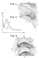
- FIG. 3 shows measurements of the local loss P according to the distance (y) to the floor 1 or to the ceiling 2 of the blade grid.
- the solid line curve (a) shows the evolution of the loss for a grid that does not have suction in the channel. Near the wall the loss is significant because of the boundary layer which forms on this wall. It decreases when you move away from the wall and then starts to grow again: these are the losses dissipated in the passing vortex: then the loss decreases again when you move away from the wall; far enough from the walls, the loss is simply due to the boundary layers which develop on the blades.
- Curves (b) and (c) represent these same changes in loss in the case of a grid of blades having a suction slot as shown in FIG. 2.
- the loss (curve b) is very markedly increased.
- the loss decreases (curve c) but for a percentage of suction flow of 3% of the main flow, which becomes very important, the overall loss is even greater than the loss in the blade grid without suction .
- the reason for this poor performance is to be found in the flow in the suction slot.
- the pressure is not constant along the suction slot; also at certain places in the slit, where the pressure is the highest, the fluid will be effectively sucked up, but it can be reinjected into the vein at another place in the slit where the pressure is weakest; this reinjection is accompanied, of course, by significant losses.
- Figure 4 shows two extreme positions of the slot according to the invention.
- the isobaric lines 5 drawn from a calculation of the grid of two-dimensional blades have been drawn.
- Such a calculation (accessible to all those skilled in the art who deal with turbomachines) makes it possible to know the characteristics of the flow sufficiently far from the walls. Near the walls the characteristics of the flow are very different, as regards the modulus and the direction of the velocities of the fluid, but we know that the static pressures are only very little modified compared to the static pressures in a section distant from the walls.
- Figure 4 shows two extreme positions of the slot 4, 4 '.
- the suction slot 4, 4 ′ is arranged in the vicinity of the vane A. Its first end 6 is located along the upper surface in a range from the zone of maximum curvature 7 to the neck 8 of channel 3.
- the slot 4, 4 ′ is rectilinear and directed along an isobaric line. Its second end 9 is separated by a third of the minimum width of the channel 3 which corresponds to the width of the neck 8.
- the slot is limited in length to its useful part near the upper surface to minimize the suction flow.
- FIG. 5 shows (curve d) the losses measured P with suction through a slot 4 according to the invention. There is a significant gain compared to the losses measured in the absence of any suction device (curve a).
- FIG. 6 shows another case of application of the invention to a grid of movable blades where the isobaric lines have a shape quite different from that of FIG. 4.
- FIG. 7 shows two stages 10 of the turbine, each consisting of a grid of fixed blades 11 and a grid of movable blades 12. This figure makes it possible to understand how the suction is carried out.
- the suction slot 4 is connected by a channel 13 which opens out through an orifice 14 in a chamber of the seal 15 located at the top of the movable grids 12 of the next stage.
- the significant expansion in the fixed grates allows the pressure difference necessary for suction to be obtained.
- a radial (or oblique) conduit 16 is drilled in the thickness of the blade which connects the slot 4, formed in the floor of the channel (radius R1) with the chamber 17 furthest downstream from the seal. located at the top (radius R2). The communication between the slot 4 and the radial duct 16 takes place via a link 18 (see FIG. 8).
- the total flow which arrives in the lining through the orifice 14 or through the conduit 16 is less than or equal to the leak flow which would normally pass through these linings in the absence of these aspirations: almost all of the gain due to the the improvement of secondary losses is thus saved.
Landscapes
- Engineering & Computer Science (AREA)
- Mechanical Engineering (AREA)
- General Engineering & Computer Science (AREA)
- Physics & Mathematics (AREA)
- Fluid Mechanics (AREA)
- Structures Of Non-Positive Displacement Pumps (AREA)
- Turbine Rotor Nozzle Sealing (AREA)
Claims (5)
- Schaufelgitter für eine Turbomaschine, das Schaufeln (A, B) zwischen einem Boden (1) und einer Decke (2) aufweist und bei dem der Boden (1) und/oder die Decke (2) mit einem Saugschlitz (4, 4') in der Nähe mindestens bestimmter Schaufeln (A) versehen ist, wobei ein erstes Ende (6) des Schlitzes (4, 4') sich entlang der Außenseite in einem Bereich der Schaufel (A) befindet, der von der maximalen Krümmungszone (7) bis zum Sattel (8) des Kanals (3) zwischen dieser Schaufel (A) und der benachbarten Schaufel (B) verläuft, dadurch gekennzeichnet, daß dieser Schlitz (4, 4') entlang einer Linie gleichen Drucks ausgerichtet ist und eine solche Länge hat, daß das zweite Ende (9) von der Außenseite der Schaufel (A) einen Abstand besitzt, der zwischen einem Viertel und der Hälfte der Breite des Sattels (8) des Kanals (3) liegt.
- Turbomaschine mit mehreren Stufen (10), die je aus einem festen Schaufelgitter (11) gefolgt von einem beweglichen Schaufelgitter (12) bestehen, wobei die Schaufeln eines Gitters (11, 12) sich zwischen einem Boden (1) und einer Decke (2) erstrecken, wobei die Decke (2) der beweglichen Gitter (12) mit einer Dichtung (15) versehen ist, die mit dem vor ihr liegenden Bereich des Rotors mehrere Kammern (17, 17') definiert, wobei die Decke (2) des festen Schaufelgitters (11) zumindest in der Nähe bestimmter Schaufeln einen Saugschlitz (4) aufweist, dessen erstes Ende (6) sich entlang der Außenseite in einem Bereich befindet, der von der maximalen Krümmungszone (7) zum Sattel (8) des Kanals (3) zwischen dieser Schaufel (A) und der benachbarten Schaufel (B) verläuft, dadurch gekennzeichnet, daß dieser Schlitz (4) entlang einer Linie gleichen Drucks ausgerichtet ist und eine solche Länge hat, daß das zweite Ende (9) von der Außenseite einen Abstand aufweist, der zwischen einem Viertel und der Hälfte der Breite des Sattels (8) des Kanals (3) liegt, wobei dieser Schlitz (4) mit einem Punkt (14) niedrigeren Drucks der Turbomaschine verbunden ist.
- Turbomaschine nach Anspruch 2, dadurch gekennzeichnet, daß der Schlitz (4) über einen Kanal mit einer der stromabwärtsliegenden Kammern (17) der Dichtung (15) des beweglichen Gitters (12) der folgenden Stufe (10) verbunden ist.
- Turbomaschine mit mehreren Stufen (10), die je aus einem festen Schaufelgitter (11) gefolgt von einem beweglichen Schaufelgitter (12) bestehen, wobei sich die Schaufeln eines Gitters (11, 12) zwischen einem Boden (1) und einer Decke (2) erstrecken und wobei die Decke (2) der beweglichen Gitter (12) mit einer Dichtung (15) versehen ist die mit dem vor ihr liegenden Bereich des Rotors mehrere Kammern (17, 17') definiert, dadurch gekennzeichnet, daß der Boden (1) der beweglichen Schaufelgitter (12) in der Nähe zumindest bestimmter Schaufeln (A) mit einem Saugschlitz (4) verbunden ist, dessen erstes Ende (6) sich entlang der Außenseite in einem Bereich befindet, der von der maximalen Krümmungszone (7) bis zum Sattel (8) des Kanals (3) zwischen dieser Schaufel (A) und der benachbarten Schaufel (B) verläuft, wobei dieser Schlitz (4) entlang einer Linie gleichen Drucks ausgerichtet ist und eine solche Länge hat, daß das zweite Ende (9) von der Außenseite einen Abstand hat, der zwischen einem Viertel und der Hälfte der Breite des Sattels (8) des Kanals (3) liegt, und daß dieser Schlitz (4) mit einem Kanal (16) verbunden ist, der die Schaufel von unten nach oben durchquert und hinter der Dichtung oder in eine der letzten Kammern (17, 17') dieser Dichtung (15) mündet.
- Turbomaschine nach einem der Ansprüche 2 bis 4, dadurch gekennzeichnet, daß das zweite Ende (9) des Schlitzes (4) zur Außenseite der entsprechenden Schaufel einen Abstand besitzt, der etwa einem Drittel der Breite des Sattels (8) des entsprechenden Kanals (3) entspricht.
Applications Claiming Priority (2)
| Application Number | Priority Date | Filing Date | Title |
|---|---|---|---|
| FR9011336A FR2666846B1 (fr) | 1990-09-13 | 1990-09-13 | Grille d'aubes pour turbomachine munie de fentes d'aspiration dans le plafond et/ou dans le plancher et turbomachine comportant ces grilles. |
| FR9011336 | 1990-09-13 |
Publications (3)
| Publication Number | Publication Date |
|---|---|
| EP0475329A2 EP0475329A2 (de) | 1992-03-18 |
| EP0475329A3 EP0475329A3 (en) | 1992-06-03 |
| EP0475329B1 true EP0475329B1 (de) | 1994-11-30 |
Family
ID=9400301
Family Applications (1)
| Application Number | Title | Priority Date | Filing Date |
|---|---|---|---|
| EP91115218A Expired - Lifetime EP0475329B1 (de) | 1990-09-13 | 1991-09-09 | Schaufelgitter für Turbomaschinen mit Saugschlitzen |
Country Status (10)
| Country | Link |
|---|---|
| US (1) | US5232338A (de) |
| EP (1) | EP0475329B1 (de) |
| JP (1) | JPH04279701A (de) |
| CN (1) | CN1060891A (de) |
| AT (1) | ATE114780T1 (de) |
| CS (1) | CS281991A3 (de) |
| DE (1) | DE69105418T2 (de) |
| FR (1) | FR2666846B1 (de) |
| MX (1) | MX9101073A (de) |
| ZA (1) | ZA917326B (de) |
Families Citing this family (26)
| Publication number | Priority date | Publication date | Assignee | Title |
|---|---|---|---|---|
| FR2675536B1 (fr) * | 1991-04-19 | 1994-12-09 | Alsthom Gec | Turbine a action a rotor tambour et perfectionnement a ces turbines. |
| US5632598A (en) * | 1995-01-17 | 1997-05-27 | Dresser-Rand | Shrouded axial flow turbo machine utilizing multiple labrinth seals |
| DE19620828C1 (de) * | 1996-05-23 | 1997-09-04 | Siemens Ag | Turbinenwelle sowie Verfahren zur Kühlung einer Turbinenwelle |
| US6004095A (en) * | 1996-06-10 | 1999-12-21 | Massachusetts Institute Of Technology | Reduction of turbomachinery noise |
| US5904470A (en) * | 1997-01-13 | 1999-05-18 | Massachusetts Institute Of Technology | Counter-rotating compressors with control of boundary layers by fluid removal |
| EP0894944A1 (de) * | 1997-07-29 | 1999-02-03 | Siemens Aktiengesellschaft | Turbinenbeschaufelung |
| EP1147291B1 (de) | 1998-02-26 | 2007-08-22 | Allison Advanced Development Company | Zapfsystem für eine kompressorwand sowie betriebsverfahren |
| US6595743B1 (en) * | 1999-07-26 | 2003-07-22 | Impsa International Inc. | Hydraulic seal for rotary pumps |
| US20040101410A1 (en) * | 2001-10-02 | 2004-05-27 | Oleg Naljotov | Axial flow fluid machine |
| US6632069B1 (en) * | 2001-10-02 | 2003-10-14 | Oleg Naljotov | Step of pressure of the steam and gas turbine with universal belt |
| US6682301B2 (en) * | 2001-10-05 | 2004-01-27 | General Electric Company | Reduced shock transonic airfoil |
| GB0200992D0 (en) * | 2002-01-17 | 2002-03-06 | Rolls Royce Plc | Gas turbine cooling system |
| UA81314C2 (en) * | 2003-04-18 | 2007-12-25 | Steam/gas turbine with shroud | |
| US20070069477A1 (en) * | 2003-06-20 | 2007-03-29 | Elliott Company | Stepped labyrinth damper seal |
| US20060267289A1 (en) * | 2003-06-20 | 2006-11-30 | Elliott Company | Hybrid abradable labyrinth damper seal |
| JP4346412B2 (ja) | 2003-10-31 | 2009-10-21 | 株式会社東芝 | タービン翼列装置 |
| DE10355241A1 (de) * | 2003-11-26 | 2005-06-30 | Rolls-Royce Deutschland Ltd & Co Kg | Strömungsarbeitsmaschine mit Fluidzufuhr |
| DE10355240A1 (de) * | 2003-11-26 | 2005-07-07 | Rolls-Royce Deutschland Ltd & Co Kg | Strömungsarbeitsmaschine mit Fluidentnahme |
| RU2279551C1 (ru) * | 2005-01-11 | 2006-07-10 | Открытое акционерное общество "Научно-производственное объединение по исследованию и проектированию энергетического оборудования им. И.И. Ползунова" (ОАО "НПО ЦКТИ") | Высокотемпературная многоступенчатая паровая турбина |
| DE102007027427A1 (de) * | 2007-06-14 | 2008-12-18 | Rolls-Royce Deutschland Ltd & Co Kg | Schaufeldeckband mit Überstand |
| DE102008029605A1 (de) * | 2008-06-23 | 2009-12-24 | Rolls-Royce Deutschland Ltd & Co Kg | Schaufeldeckband mit Durchlass |
| FR2958694B1 (fr) * | 2010-04-07 | 2014-04-18 | Snecma | Compresseur de moteur, en particulier de turboreacteur d'aeronef, muni d'un systeme de prelevement d'air |
| CN102364098A (zh) * | 2011-11-18 | 2012-02-29 | 三一电气有限责任公司 | 一种风力发电机组及其叶片 |
| EP2713009B1 (de) * | 2012-09-26 | 2015-03-11 | Alstom Technology Ltd | Kühlverfahren und -system zur Kühlung von Schaufeln mindestens einer Schaufelreihe in einer drehenden Strömungsmaschine |
| CN109413711B (zh) * | 2018-10-17 | 2021-02-05 | 中国运载火箭技术研究院 | 一种飞行器协同信息网络协议栈 |
| US11674406B2 (en) * | 2021-08-06 | 2023-06-13 | Pratt & Whitney Canada Corp. | Variable gap between impeller rotor and static structure |
Family Cites Families (12)
| Publication number | Priority date | Publication date | Assignee | Title |
|---|---|---|---|---|
| JPS501646B1 (de) * | 1970-07-11 | 1975-01-20 | ||
| DE2135286A1 (de) * | 1971-07-15 | 1973-01-25 | Wilhelm Prof Dr Ing Dettmering | Lauf- und leitradgitter fuer turbomaschinen |
| FR2166494A5 (de) * | 1971-12-27 | 1973-08-17 | Onera (Off Nat Aerospatiale) | |
| JPS5254809A (en) * | 1975-10-31 | 1977-05-04 | Hitachi Ltd | Axial-flow fluid machine construction |
| JPS5254807A (en) * | 1975-10-31 | 1977-05-04 | Hitachi Ltd | Axial-flow fluid machine |
| FR2438157A1 (fr) * | 1978-10-05 | 1980-04-30 | Alsthom Atlantique | Grille d'aubes pour turbine ou compresseur |
| FR2438155A1 (fr) * | 1978-10-05 | 1980-04-30 | Alsthom Atlantique | Grille d'aubes pour turbine ou compresseur et turbine ou compresseur comportant une telle grille d'aubes |
| DE2845094A1 (de) * | 1978-10-17 | 1980-05-08 | Freudenberg Carl Fa | Greifvorrichtung |
| FR2473290A1 (fr) * | 1980-01-14 | 1981-07-17 | Treboul Douarnenez Ctre Cure M | Plateau de relaxation et table comportant un tel plateau |
| JPS5752603A (en) * | 1980-09-17 | 1982-03-29 | Toshiba Corp | Leakage preventing device in turbine |
| SU1015082A1 (ru) * | 1981-07-13 | 1983-04-30 | Московский Ордена Ленина И Ордена Октябрьской Революции Энергетический Институт | Многоступенчата парова турбина |
| SU1159970A1 (ru) * | 1982-12-31 | 1985-06-07 | Всесоюзный Дважды Ордена Трудового Красного Знамени Теплотехнический Научно-Исследовательский Институт Им.Ф.Э.Дзержинского | Ступень турбомашины |
-
1990
- 1990-09-13 FR FR9011336A patent/FR2666846B1/fr not_active Expired - Lifetime
-
1991
- 1991-09-09 AT AT91115218T patent/ATE114780T1/de active
- 1991-09-09 EP EP91115218A patent/EP0475329B1/de not_active Expired - Lifetime
- 1991-09-09 DE DE69105418T patent/DE69105418T2/de not_active Expired - Fee Related
- 1991-09-12 MX MX9101073A patent/MX9101073A/es unknown
- 1991-09-13 US US07/759,372 patent/US5232338A/en not_active Expired - Fee Related
- 1991-09-13 CS CS912819A patent/CS281991A3/cs unknown
- 1991-09-13 JP JP3234871A patent/JPH04279701A/ja active Pending
- 1991-09-13 ZA ZA917326A patent/ZA917326B/xx unknown
- 1991-09-13 CN CN91109583A patent/CN1060891A/zh active Pending
Non-Patent Citations (1)
| Title |
|---|
| PATENT ABSTRACTS OF JAPAN vol. 1, no. 118 (M-77)(3758) 8 Octobre 1977, & JP-A-52 54 807 (HITACHI SEISAKUSHO K.K.) 05-04-1977 * |
Also Published As
| Publication number | Publication date |
|---|---|
| MX9101073A (es) | 1994-06-30 |
| EP0475329A2 (de) | 1992-03-18 |
| DE69105418D1 (de) | 1995-01-12 |
| US5232338A (en) | 1993-08-03 |
| ATE114780T1 (de) | 1994-12-15 |
| FR2666846A1 (fr) | 1992-03-20 |
| DE69105418T2 (de) | 1995-04-20 |
| ZA917326B (en) | 1992-05-27 |
| JPH04279701A (ja) | 1992-10-05 |
| EP0475329A3 (en) | 1992-06-03 |
| CS281991A3 (en) | 1992-03-18 |
| FR2666846B1 (fr) | 1992-10-16 |
| CN1060891A (zh) | 1992-05-06 |
Similar Documents
| Publication | Publication Date | Title |
|---|---|---|
| EP0475329B1 (de) | Schaufelgitter für Turbomaschinen mit Saugschlitzen | |
| EP3477050B1 (de) | Verdichter einer turbomaschine mit asymmetrisch konturiertem strömungsring | |
| CA2521983C (fr) | Procede de circulation d'air dans un compresseur de turbomachine, agencement de compresseur le mettant en oeuvre, etage de compression et compresseur comportant un tel agencement,et moteur d'aeronef equipe d'un tel compresseur | |
| BE1025961B1 (fr) | Passage annulaire entre une virole et une plateforme rotorique de turbomachine | |
| CA2946708C (fr) | Aube pour turbine de turbomachine comprenant un circuit de refroidissement a homogeneite amelioree | |
| EP2710268B1 (de) | Gasturbinendiffusorblasverfahren und entsprechender diffusor | |
| CA2926003C (fr) | Piece de turbomachine a surface non-axisymetrique | |
| BE1026579A1 (fr) | Aube a protuberance pour compresseur de turbomachine | |
| WO1982002418A1 (fr) | Etage de turbine | |
| EP3475532B1 (de) | Teil und verfahren zur herstellung eines teils mit reduziertem widerstand durch nicht konstante riblets | |
| WO2009103891A2 (fr) | Dispositif de soufflage de gaz sur une face d'un materiau en bande en defilement | |
| EP0020433B1 (de) | Schaufelgitter für turbine und turbine mit einem solchen schaufelgitter | |
| EP3794218A1 (de) | Turbinenschaufel mit einem passiven system zur reduzierung von wirbelphänomenen in einer über die schaufel strömenden luftströmung | |
| EP3477049B1 (de) | Axialer turbomaschinenverdichter mit ring mit erhebungen | |
| CA2838686C (fr) | Procede de diffusion d'un etage de compression d'une turbine a gaz et etage de diffusion de mise en oeuvre | |
| FR2978200A1 (fr) | Diffuseur d'echappement de turbine basse pression avec turbulateurs | |
| EP3803055B1 (de) | Profiliertes deckband für einen verdichter einer strömungsmaschine | |
| FR2927674A1 (fr) | Aube de soufflante avec aspiration en pied et soufflage au bord de fuite | |
| FR2927673A1 (fr) | Aube de soufflante avec aspiration en pied et soufflage en tete | |
| FR3065985A1 (fr) | Promoteur de turbulences d'ecoulements de ventilation pour une aube | |
| FR3152831A1 (fr) | Aubage de turbomachine | |
| EP3812548A1 (de) | Kompressorstufe einer strömungsmaschine mit optimierter innenendwand |
Legal Events
| Date | Code | Title | Description |
|---|---|---|---|
| PUAI | Public reference made under article 153(3) epc to a published international application that has entered the european phase |
Free format text: ORIGINAL CODE: 0009012 |
|
| AK | Designated contracting states |
Kind code of ref document: A2 Designated state(s): AT BE CH DE DK ES FR GB GR IT LI LU NL SE |
|
| PUAL | Search report despatched |
Free format text: ORIGINAL CODE: 0009013 |
|
| AK | Designated contracting states |
Kind code of ref document: A3 Designated state(s): AT BE CH DE DK ES FR GB GR IT LI LU NL SE |
|
| 17P | Request for examination filed |
Effective date: 19921124 |
|
| 17Q | First examination report despatched |
Effective date: 19940321 |
|
| GRAA | (expected) grant |
Free format text: ORIGINAL CODE: 0009210 |
|
| AK | Designated contracting states |
Kind code of ref document: B1 Designated state(s): AT BE CH DE DK ES FR GB GR IT LI LU NL SE |
|
| PG25 | Lapsed in a contracting state [announced via postgrant information from national office to epo] |
Ref country code: NL Effective date: 19941130 Ref country code: GR Free format text: LAPSE BECAUSE OF FAILURE TO SUBMIT A TRANSLATION OF THE DESCRIPTION OR TO PAY THE FEE WITHIN THE PRESCRIBED TIME-LIMIT Effective date: 19941130 Ref country code: ES Free format text: THE PATENT HAS BEEN ANNULLED BY A DECISION OF A NATIONAL AUTHORITY Effective date: 19941130 Ref country code: DK Effective date: 19941130 Ref country code: AT Effective date: 19941130 |
|
| REF | Corresponds to: |
Ref document number: 114780 Country of ref document: AT Date of ref document: 19941215 Kind code of ref document: T |
|
| GBT | Gb: translation of ep patent filed (gb section 77(6)(a)/1977) |
Effective date: 19941212 |
|
| REF | Corresponds to: |
Ref document number: 69105418 Country of ref document: DE Date of ref document: 19950112 |
|
| ITF | It: translation for a ep patent filed | ||
| PG25 | Lapsed in a contracting state [announced via postgrant information from national office to epo] |
Ref country code: SE Effective date: 19950228 |
|
| NLV1 | Nl: lapsed or annulled due to failure to fulfill the requirements of art. 29p and 29m of the patents act | ||
| PG25 | Lapsed in a contracting state [announced via postgrant information from national office to epo] |
Ref country code: LU Free format text: LAPSE BECAUSE OF NON-PAYMENT OF DUE FEES Effective date: 19950930 Ref country code: BE Effective date: 19950930 |
|
| PLBE | No opposition filed within time limit |
Free format text: ORIGINAL CODE: 0009261 |
|
| STAA | Information on the status of an ep patent application or granted ep patent |
Free format text: STATUS: NO OPPOSITION FILED WITHIN TIME LIMIT |
|
| 26N | No opposition filed | ||
| BERE | Be: lapsed |
Owner name: S.A. GEC ALSTHOM Effective date: 19950930 |
|
| PGFP | Annual fee paid to national office [announced via postgrant information from national office to epo] |
Ref country code: GB Payment date: 19990813 Year of fee payment: 9 |
|
| PGFP | Annual fee paid to national office [announced via postgrant information from national office to epo] |
Ref country code: CH Payment date: 19990816 Year of fee payment: 9 |
|
| PGFP | Annual fee paid to national office [announced via postgrant information from national office to epo] |
Ref country code: FR Payment date: 19990817 Year of fee payment: 9 |
|
| PGFP | Annual fee paid to national office [announced via postgrant information from national office to epo] |
Ref country code: DE Payment date: 19990820 Year of fee payment: 9 |
|
| PG25 | Lapsed in a contracting state [announced via postgrant information from national office to epo] |
Ref country code: GB Free format text: LAPSE BECAUSE OF NON-PAYMENT OF DUE FEES Effective date: 20000909 |
|
| PG25 | Lapsed in a contracting state [announced via postgrant information from national office to epo] |
Ref country code: LI Free format text: LAPSE BECAUSE OF NON-PAYMENT OF DUE FEES Effective date: 20000930 Ref country code: CH Free format text: LAPSE BECAUSE OF NON-PAYMENT OF DUE FEES Effective date: 20000930 |
|
| GBPC | Gb: european patent ceased through non-payment of renewal fee |
Effective date: 20000909 |
|
| REG | Reference to a national code |
Ref country code: CH Ref legal event code: PL |
|
| PG25 | Lapsed in a contracting state [announced via postgrant information from national office to epo] |
Ref country code: FR Free format text: LAPSE BECAUSE OF NON-PAYMENT OF DUE FEES Effective date: 20010531 |
|
| PG25 | Lapsed in a contracting state [announced via postgrant information from national office to epo] |
Ref country code: DE Free format text: LAPSE BECAUSE OF NON-PAYMENT OF DUE FEES Effective date: 20010601 |
|
| REG | Reference to a national code |
Ref country code: FR Ref legal event code: ST |
|
| PG25 | Lapsed in a contracting state [announced via postgrant information from national office to epo] |
Ref country code: IT Free format text: LAPSE BECAUSE OF NON-PAYMENT OF DUE FEES;WARNING: LAPSES OF ITALIAN PATENTS WITH EFFECTIVE DATE BEFORE 2007 MAY HAVE OCCURRED AT ANY TIME BEFORE 2007. THE CORRECT EFFECTIVE DATE MAY BE DIFFERENT FROM THE ONE RECORDED. Effective date: 20050909 |