EP0475332A2 - Entwicklerrührverfahren und -gerät - Google Patents
Entwicklerrührverfahren und -gerät Download PDFInfo
- Publication number
- EP0475332A2 EP0475332A2 EP91115222A EP91115222A EP0475332A2 EP 0475332 A2 EP0475332 A2 EP 0475332A2 EP 91115222 A EP91115222 A EP 91115222A EP 91115222 A EP91115222 A EP 91115222A EP 0475332 A2 EP0475332 A2 EP 0475332A2
- Authority
- EP
- European Patent Office
- Prior art keywords
- developer
- spiral
- toner
- agitating
- carrying
- Prior art date
- Legal status (The legal status is an assumption and is not a legal conclusion. Google has not performed a legal analysis and makes no representation as to the accuracy of the status listed.)
- Granted
Links
- 238000000034 method Methods 0.000 title claims abstract description 12
- 238000013019 agitation Methods 0.000 claims description 4
- 230000007423 decrease Effects 0.000 description 4
- 230000035699 permeability Effects 0.000 description 4
- 238000005192 partition Methods 0.000 description 3
- 238000012986 modification Methods 0.000 description 1
- 230000004048 modification Effects 0.000 description 1
- 108091008695 photoreceptors Proteins 0.000 description 1
Images




Classifications
-
- G—PHYSICS
- G03—PHOTOGRAPHY; CINEMATOGRAPHY; ANALOGOUS TECHNIQUES USING WAVES OTHER THAN OPTICAL WAVES; ELECTROGRAPHY; HOLOGRAPHY
- G03G—ELECTROGRAPHY; ELECTROPHOTOGRAPHY; MAGNETOGRAPHY
- G03G15/00—Apparatus for electrographic processes using a charge pattern
- G03G15/06—Apparatus for electrographic processes using a charge pattern for developing
- G03G15/08—Apparatus for electrographic processes using a charge pattern for developing using a solid developer, e.g. powder developer
- G03G15/0822—Arrangements for preparing, mixing, supplying or dispensing developer
-
- G—PHYSICS
- G03—PHOTOGRAPHY; CINEMATOGRAPHY; ANALOGOUS TECHNIQUES USING WAVES OTHER THAN OPTICAL WAVES; ELECTROGRAPHY; HOLOGRAPHY
- G03G—ELECTROGRAPHY; ELECTROPHOTOGRAPHY; MAGNETOGRAPHY
- G03G15/00—Apparatus for electrographic processes using a charge pattern
- G03G15/06—Apparatus for electrographic processes using a charge pattern for developing
- G03G15/08—Apparatus for electrographic processes using a charge pattern for developing using a solid developer, e.g. powder developer
- G03G15/0822—Arrangements for preparing, mixing, supplying or dispensing developer
- G03G15/0848—Arrangements for testing or measuring developer properties or quality, e.g. charge, size, flowability
- G03G15/0849—Detection or control means for the developer concentration
-
- G—PHYSICS
- G03—PHOTOGRAPHY; CINEMATOGRAPHY; ANALOGOUS TECHNIQUES USING WAVES OTHER THAN OPTICAL WAVES; ELECTROGRAPHY; HOLOGRAPHY
- G03G—ELECTROGRAPHY; ELECTROPHOTOGRAPHY; MAGNETOGRAPHY
- G03G15/00—Apparatus for electrographic processes using a charge pattern
- G03G15/06—Apparatus for electrographic processes using a charge pattern for developing
- G03G15/08—Apparatus for electrographic processes using a charge pattern for developing using a solid developer, e.g. powder developer
- G03G15/0822—Arrangements for preparing, mixing, supplying or dispensing developer
- G03G15/0848—Arrangements for testing or measuring developer properties or quality, e.g. charge, size, flowability
- G03G15/0849—Detection or control means for the developer concentration
- G03G15/0853—Detection or control means for the developer concentration the concentration being measured by magnetic means
-
- G—PHYSICS
- G03—PHOTOGRAPHY; CINEMATOGRAPHY; ANALOGOUS TECHNIQUES USING WAVES OTHER THAN OPTICAL WAVES; ELECTROGRAPHY; HOLOGRAPHY
- G03G—ELECTROGRAPHY; ELECTROPHOTOGRAPHY; MAGNETOGRAPHY
- G03G15/00—Apparatus for electrographic processes using a charge pattern
- G03G15/06—Apparatus for electrographic processes using a charge pattern for developing
- G03G15/08—Apparatus for electrographic processes using a charge pattern for developing using a solid developer, e.g. powder developer
- G03G15/0822—Arrangements for preparing, mixing, supplying or dispensing developer
- G03G15/0887—Arrangements for conveying and conditioning developer in the developing unit, e.g. agitating, removing impurities or humidity
- G03G15/0891—Arrangements for conveying and conditioning developer in the developing unit, e.g. agitating, removing impurities or humidity for conveying or circulating developer, e.g. augers
- G03G15/0893—Arrangements for conveying and conditioning developer in the developing unit, e.g. agitating, removing impurities or humidity for conveying or circulating developer, e.g. augers in a closed loop within the sump of the developing device
-
- G—PHYSICS
- G03—PHOTOGRAPHY; CINEMATOGRAPHY; ANALOGOUS TECHNIQUES USING WAVES OTHER THAN OPTICAL WAVES; ELECTROGRAPHY; HOLOGRAPHY
- G03G—ELECTROGRAPHY; ELECTROPHOTOGRAPHY; MAGNETOGRAPHY
- G03G2215/00—Apparatus for electrophotographic processes
- G03G2215/08—Details of powder developing device not concerning the development directly
- G03G2215/0802—Arrangements for agitating or circulating developer material
- G03G2215/0816—Agitator type
- G03G2215/0827—Augers
- G03G2215/0833—Augers with varying pitch on one shaft
Definitions
- the present invention relates to a developer agitating method and a developer agitating apparatus which are employed for image forming apparatuses such as electrophotographic copying machines, printers, etc.
- Multi-color electrophotographic copying machines are provided with a plurality of developer units. Therefore, in order to prevent the whole body of the copying machine from increasing in size, it is required to make each developer unit compact.
- a method for compact developer units, where an agitation direction is increased, as shown in Fig. 1, by circulating the developer by use of a spirals 10a and 10b on an agitating passage 45 along a partition 15 in a direction along a development sleeve 20.
- the arrows in Fig. 1 show the direction of the flow of the developer.
- a T/D (wherein T represents an amount of toner and D represents an amount of developer) of the developer is sensed by a toner density sensor 30 consisting of a permeability sensor provided at the bottom of the agitating passage 45 to control an amount of toner supplied through a toner supply mouth 60.
- the amount of developer which is provided in a developer unit is an important factor for controlling the T/D of the developer.
- the amount of the developer temporarily decreases, so that the spiral 10a is over-exposed out of the developer.
- the carrier included in the developer hardly contacts the toner density sensor 30 provided at the bottom of the agitating passage 45 because of an increase of air included in the developer, so that a sensing voltage decreases to stop the toner supply.
- the toner density sensor 30 senses a carrier density in the developer from a permeability of the developer to obtain the T/D.
- the toner density temporarily exceeds a reference value so that a fan 12 of the spiral 10a is nearly covered with the developer such as when the original to be copied is changed from an original having a large toner consumption area to an original having a small area
- the developer on the surface is carried without mixed with the supplied toner.
- the supplied toner is carried with the developer on the surface of the developer and is never sensed by the toner density sensor 30 provided at the bottom of the agitating passage 45. Therefore, the toner supply never stops, so that toner is over-supplied to further increase the amount of the developer.
- a vicious cycle arises where the fan 12 of the spiral 10a is covered with the developer and the further supplied toner is never sensed by the toner density sensor 30 so that the toner scatters out of the developer unit.
- An object of the present invention is to provide a developer agitating method and a developer agitating apparatus where an erroneous sensing of toner density in the developer by the toner density sensor can be prevented.
- carrier which is previously provided on an agitating passage and toner which is supplied on the agitating passage through a toner supply mouth are mixed by use of a spiral and where a developer consisting of said toner and carrier is circulated in a direction along to an axis of said spiral by use of said spiral, and a section where a speed of carrying the developer is high and a section where a speed of carrying the developer is low are provided in a direction along the axis of the spiral and an agitation is performed so that a part of said spiral is exposed out of the developer in the section where the carrying speed is high.
- a developer agitating apparatus is provided with an agitating passage to which carrier and toner are supplied as a developer, a spiral provided on said agitating passage and having a restricting member, between a part of portions between its fans, for reducing a performance of carrying the developer, a toner density sensor provided at a bottom of a portion, of said agitating passage, where said restricting member is provided and a toner supply mouth provided at an upper part, of said agitating passage, where said restricting plate is not provided.
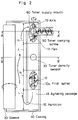
- Fig. 2 is a plan view of a developing apparatus where the present invention is incorporated.
- a development sleeve 20 is provided at a position opposite to a photoreceptor drum (not shown) so that it is partly exposed out of the casing 40.
- a partition 15 is provided parallelly to a direction along the development sleeve 20.
- a toner supply mouth 60 is provided at a portion on the upper surface of the side, with the partition 15 in the center, where the development sleeve 20 is not provided of the casing 40.
- a toner carrying screw 50 is rotated, a toner 70 is supplied into the casing 40 through the toner supply mouth 60 as shown in Fig. 4 (a cross-sectional view taken on the line A-A' of Fig. 2). Then, the toner 70 is immediately mixed with a developer 80 by a fan 12 of a first spiral 10a which is partly exposed out of the developer 80.
- the toner supply mouth 60 is provided at an upper surface of the casing 40 as shown in Figs. 2 and 4, and a toner density sensor 30, at a bottom of the casing 40 as shown in Figs. 2 and 5.
- the first spiral 10a is provided on an agitating passage 45.
- the toner density sensor 30 consists of a permeability sensor.
- a motor 200 which rotates the toner carrying screw 50 is controlled by an output of the toner density sensor 30, whereby a toner supply from the toner supply mouth 60 to the agitating passage 45 is controlled.
- the numeral 300 represents a toner hopper.
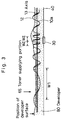
- a pitch W1 of the portions of the first spiral 10a which are located below the toner supply mouth 60 is, as shown in Fig. 3, longer than a pitch W2 of the portions of the first spiral 10a which are located above the toner density sensor 30. Therefore, the speed of carrying the developer 80 is higher at the portions where the pitch is longer than the portions above the toner density sensor 30.
- Fig. 2 shows only portions of the first spiral 10a where the pitch is longer (that is, where the carrying speed is high) in order to show a condition where the fan 12 of the first spiral 10a and an axis 13 are exposed out of the developer 80 because of the high speed of carrying the developer 80.
- the pitch W2 of the portions of the first spiral 10a which is located above the toner density sensor 30 is shorter than the pitch W1 of the portions of the first spiral 10a which is located below the toner supply mouth 60. Therefore, the speed of carrying the developer 80 is lower at the portions where the pitch is shorter than at the portions where the pitch is longer. Therefore, the first spiral 10a is sufficiently covered with the developer 80 as shown in Fig. 5 (a cross-sectional view taken on the line B-B' of Fig. 2), so that the toner density sensor 30 and the developer 80 satisfactorily contact.
- the motor 200 rotates to rotate the toner carrying screw 50, so that the toner 70 is supplied through the toner supply mouth 60.
- the portion where the pitch is short (a low-speed section) L and the portion where the pitch is longer (a high-speed section) H are alternately formed. Therefore, as shown in Fig. 3, the longer the pitch is, the more the first spiral 10a is exposed out of the developer 80, and the shorter the pitch is, the more the first spiral 10a is covered with the developer 80.
- the amount of the developer 80 is controlled so that a part of the first spiral 10a is exposed out of the developer 80, for example, so that the height of the developer 80 does not exceed the height (a height from the bottom of the agitating passage 45) of an axis 90 of the first spiral 10a at the portions where the pitch is longer.
- the toner supplied at the portions where the pitch is longer is swallowed by the developer crumbling like an avalanche against a rotation direction of the first spiral 10a and is mixed with the developer.
- the developer 80 is heaped up on the portion where the pitch is shorter, and due to the dead load, the excessive developer 80 flows toward the portion where the pitch is longer.
- Fig. 3 shows a manner in which the developer 80 is distributed on the agitating passage 45 when the first spiral 10a is operated.
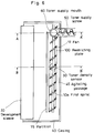
- Fig. 6 shows another embodiment of the present invention.
- the portions the same as those shown in Fig. 2 are represented by the same numerals.
- a restricting plate 100 for restricting the amount of carried toner is provided between the fans 12 of a portion of the first spiral 10a other than the portion in the vicinity of the position below the toner supply mouth.
- the restricting plate 100 sufficiently rotates the developer in a rotation direction of the spiral 10a. Thus, the speed of carrying toner in a direction along the axis decreases.
- the first spiral 10a is sufficiently covered with the developer 80 in the vicinity of the toner density sensor 30, so that the toner density sensor 30 and the developer 80 satisfactorily contact.
- a T/D sensed by the toner density sensor 30 is smaller than a predetermined value
- the toner 70 is supplied through the toner supply mouth 60.
- the restriction plate 100 is not provided between the fans 12 of the first spiral 10a in the vicinity of the portion below the toner supply mouth 60. Therefore, the portion of the spiral barely rotates the developer around the axis, and thus, the speed of carrying the developer along the axis increases. For this reason, the developer remains for only a short period of time and the amount of the developer decreases. As a result, the fan of the spiral is exposed, and the toner supplied therein is swallowed up by the developer crumbling like an avalanche between the fans against a rotation direction, is immediately mixed with the developer and is uniformly dispersed in the developer.
- Fig. 7 shows a manner in which the developer 80 is distributed on the agitating passage 45 when the first spiral 10a is operated.
- the toner supply mouth is provided in the portion where the speed is high, and the toner density sensor is provided in the portion where the speed is low.
- the developer remains for only a short period of time in the vicinity of a position below the toner supply mouth so that only a small quantity of developer exists.
- a part of the spiral is exposed out of the developer. Therefore, the toner supplied therein is swallowed up by the developer crumbling like an avalanche between the fans against a rotation direction, is immediately mixed with the developer and is uniformly dispersed in the developer.
- the speed of carrying the developer is low, so that the developer remains there for a longer period of time to increase the amount of the developer. Therefore, the toner is easily contact the toner density sensor, so that a correct toner density is detected.
Landscapes
- Physics & Mathematics (AREA)
- General Physics & Mathematics (AREA)
- Dry Development In Electrophotography (AREA)
Applications Claiming Priority (4)
| Application Number | Priority Date | Filing Date | Title |
|---|---|---|---|
| JP2245284A JP2633982B2 (ja) | 1990-09-14 | 1990-09-14 | 現像剤撹拌装置 |
| JP245284/90 | 1990-09-14 | ||
| JP2245283A JP2633981B2 (ja) | 1990-09-14 | 1990-09-14 | 現像剤攪拌装置 |
| JP245283/90 | 1990-09-14 |
Publications (3)
| Publication Number | Publication Date |
|---|---|
| EP0475332A2 true EP0475332A2 (de) | 1992-03-18 |
| EP0475332A3 EP0475332A3 (en) | 1992-05-20 |
| EP0475332B1 EP0475332B1 (de) | 1996-03-20 |
Family
ID=26537147
Family Applications (1)
| Application Number | Title | Priority Date | Filing Date |
|---|---|---|---|
| EP91115222A Expired - Lifetime EP0475332B1 (de) | 1990-09-14 | 1991-09-09 | Entwicklerrührverfahren und -gerät |
Country Status (3)
| Country | Link |
|---|---|
| US (1) | US5166732A (de) |
| EP (1) | EP0475332B1 (de) |
| DE (1) | DE69118063T2 (de) |
Cited By (7)
| Publication number | Priority date | Publication date | Assignee | Title |
|---|---|---|---|---|
| EP0529807A3 (en) * | 1991-08-26 | 1993-05-12 | Xerox Corporation | Improved developer auger for use in an electrophotographic printing machine |
| EP0997790A3 (de) * | 1998-10-29 | 2001-08-01 | Canon Kabushiki Kaisha | Entwicklerempfangvorrichtung |
| EP1437627A1 (de) | 2003-01-09 | 2004-07-14 | Ricoh Company | Toner-Zuführvorrichtung, Toner, elektrophotographisches Gerät mit Toner-Zuführvorrichtung und Toner |
| CN102103344A (zh) * | 2009-12-21 | 2011-06-22 | 京瓷美达株式会社 | 显影装置以及具有该显影装置的图像形成装置 |
| EP2511773A1 (de) * | 2011-04-15 | 2012-10-17 | Kyocera Document Solutions Inc. | Entwicklerkartusche und Bilderzeugungsvorrichtung, auf die die Entwicklerkartusche angewandt wird |
| EP2511771A1 (de) * | 2011-04-15 | 2012-10-17 | Kyocera Document Solutions Inc. | Bilderzeugungsvorrichtung |
| EP2511775A3 (de) * | 2011-04-14 | 2013-05-15 | Kyocera Document Solutions Inc. | Bilderzeugungsvorrichtung |
Families Citing this family (7)
| Publication number | Priority date | Publication date | Assignee | Title |
|---|---|---|---|---|
| US5532790A (en) * | 1992-11-13 | 1996-07-02 | Minolta Camera Kabushiki Kaisha | Device for optically detecting an amount of remaining developer in an image forming apparatus |
| US5682583A (en) * | 1993-06-10 | 1997-10-28 | Minolta Camera Kabushiki Kaisha | Developing device for mixing and supplying developer |
| DE69502043T2 (de) * | 1994-03-11 | 1998-08-13 | Xeikon N.V., Mortsel | Entwicklungseinheit für die Verwendung in einem elektrostatographischen Druckgerät |
| JP4330608B2 (ja) * | 2006-11-09 | 2009-09-16 | シャープ株式会社 | 現像装置および画像形成装置 |
| JP4605258B2 (ja) * | 2008-06-12 | 2011-01-05 | コニカミノルタビジネステクノロジーズ株式会社 | 現像装置および画像形成装置 |
| JP5586556B2 (ja) * | 2011-09-30 | 2014-09-10 | 京セラドキュメントソリューションズ株式会社 | 現像剤補給装置、およびそれを備えた現像装置および画像形成装置 |
| US9014577B2 (en) | 2012-12-17 | 2015-04-21 | Xerox Corporation | Carrier dispense rate measurement |
Family Cites Families (11)
| Publication number | Priority date | Publication date | Assignee | Title |
|---|---|---|---|---|
| US3167455A (en) * | 1963-01-31 | 1965-01-26 | Dick Co Ab | Developer for facsimile printing machine |
| US3664299A (en) * | 1970-12-07 | 1972-05-23 | Eg & G Inc | Electrostatic recording paper toner section |
| JPS5995581A (ja) * | 1982-11-25 | 1984-06-01 | Ricoh Co Ltd | 回収トナ−の搬送装置 |
| JPS59100472A (ja) * | 1982-12-01 | 1984-06-09 | Fuji Xerox Co Ltd | トナ−供給装置 |
| US4784081A (en) * | 1986-01-17 | 1988-11-15 | Siemens Aktiengesellschaft | Mixing device for cross-blending of developer mix in developing stations of electrophotographic printer devices |
| JPS63298369A (ja) * | 1987-05-29 | 1988-12-06 | Canon Inc | 現像装置 |
| JPS6435579A (en) * | 1987-07-31 | 1989-02-06 | Toshiba Corp | Image forming device |
| DE3826568A1 (de) * | 1987-08-05 | 1989-02-16 | Minolta Camera Kk | Reinigungseinrichtung fuer toner-detektorsensor |
| US4937625A (en) * | 1987-08-28 | 1990-06-26 | Sharp Kabushiki Kaisha | Developing device for copier |
| JPS6461779A (en) * | 1987-09-02 | 1989-03-08 | Fuji Xerox Co Ltd | Toner collecting device |
| JPH0193759A (ja) * | 1987-10-05 | 1989-04-12 | Canon Inc | カラー画像形成方法及びその装置 |
-
1991
- 1991-09-06 US US07/756,032 patent/US5166732A/en not_active Expired - Lifetime
- 1991-09-09 DE DE69118063T patent/DE69118063T2/de not_active Expired - Fee Related
- 1991-09-09 EP EP91115222A patent/EP0475332B1/de not_active Expired - Lifetime
Cited By (11)
| Publication number | Priority date | Publication date | Assignee | Title |
|---|---|---|---|---|
| EP0529807A3 (en) * | 1991-08-26 | 1993-05-12 | Xerox Corporation | Improved developer auger for use in an electrophotographic printing machine |
| EP0997790A3 (de) * | 1998-10-29 | 2001-08-01 | Canon Kabushiki Kaisha | Entwicklerempfangvorrichtung |
| US6456809B1 (en) | 1998-10-29 | 2002-09-24 | Canon Kabushiki Kaisha | Developing-agent receiving device featuring a storage part and first and second stirring members |
| EP1437627A1 (de) | 2003-01-09 | 2004-07-14 | Ricoh Company | Toner-Zuführvorrichtung, Toner, elektrophotographisches Gerät mit Toner-Zuführvorrichtung und Toner |
| US7024140B2 (en) | 2003-01-09 | 2006-04-04 | Ricoh Company, Ltd. | Toner feeder, toner, and electrophotographic image forming apparatus using the toner feeder and toner |
| CN102103344A (zh) * | 2009-12-21 | 2011-06-22 | 京瓷美达株式会社 | 显影装置以及具有该显影装置的图像形成装置 |
| CN102103344B (zh) * | 2009-12-21 | 2013-03-06 | 京瓷办公信息系统株式会社 | 显影装置以及具有该显影装置的图像形成装置 |
| EP2511775A3 (de) * | 2011-04-14 | 2013-05-15 | Kyocera Document Solutions Inc. | Bilderzeugungsvorrichtung |
| EP2511773A1 (de) * | 2011-04-15 | 2012-10-17 | Kyocera Document Solutions Inc. | Entwicklerkartusche und Bilderzeugungsvorrichtung, auf die die Entwicklerkartusche angewandt wird |
| EP2511771A1 (de) * | 2011-04-15 | 2012-10-17 | Kyocera Document Solutions Inc. | Bilderzeugungsvorrichtung |
| US8693927B2 (en) | 2011-04-15 | 2014-04-08 | Kyocera Document Solutions Inc. | Developer case and image forming apparatus to which developer case is applied |
Also Published As
| Publication number | Publication date |
|---|---|
| EP0475332B1 (de) | 1996-03-20 |
| DE69118063T2 (de) | 1996-08-08 |
| DE69118063D1 (de) | 1996-04-25 |
| EP0475332A3 (en) | 1992-05-20 |
| US5166732A (en) | 1992-11-24 |
Similar Documents
| Publication | Publication Date | Title |
|---|---|---|
| EP0475332A2 (de) | Entwicklerrührverfahren und -gerät | |
| JP4070387B2 (ja) | 現像装置及び画像形成装置 | |
| US5214476A (en) | Image forming apparatus | |
| US4956668A (en) | Developer mix monitoring for replaceable developer stations | |
| JP3120562B2 (ja) | 現像装置 | |
| US5724635A (en) | Developing device and image forming apparatus using the developing device | |
| EP0658825A2 (de) | Entwicklungsgerät für latente elektrostatische Bilder | |
| US5950056A (en) | Developing device provided with three developer transport members | |
| JP2633981B2 (ja) | 現像剤攪拌装置 | |
| US5043764A (en) | Replaceable developer station having indicator for determining whether developer station is used or new | |
| US5034773A (en) | Developing unit with a member for agitating the toners in a developer | |
| JPH04125661A (ja) | 電子写真装置の現像剤撹拌装置 | |
| JP3398486B2 (ja) | 画像形成装置 | |
| JP4180687B2 (ja) | トナー供給方法およびその装置 | |
| JP2633982B2 (ja) | 現像剤撹拌装置 | |
| JPH04119378A (ja) | 現像装置 | |
| JP2875610B2 (ja) | 現像装置 | |
| JPH0683184A (ja) | 現像装置 | |
| JP2506225Y2 (ja) | 現像装置 | |
| JPS59114557A (ja) | 現像剤撹「はん」装置 | |
| JPH0836294A (ja) | 現像装置及び画像形成装置 | |
| JPH0732657U (ja) | 現像装置 | |
| EP0529325B1 (de) | Vorrichtung zum Zuführen von Entwicklerpulver in einem Bilderzeugungsgerät | |
| KR100260425B1 (ko) | 전자사진 프로세서의 화상형성장치 | |
| JP3237084B2 (ja) | 現像装置 |
Legal Events
| Date | Code | Title | Description |
|---|---|---|---|
| PUAI | Public reference made under article 153(3) epc to a published international application that has entered the european phase |
Free format text: ORIGINAL CODE: 0009012 |
|
| AK | Designated contracting states |
Kind code of ref document: A2 Designated state(s): DE FR GB IT |
|
| PUAL | Search report despatched |
Free format text: ORIGINAL CODE: 0009013 |
|
| AK | Designated contracting states |
Kind code of ref document: A3 Designated state(s): DE FR GB IT |
|
| 17P | Request for examination filed |
Effective date: 19921113 |
|
| 17Q | First examination report despatched |
Effective date: 19940524 |
|
| GRAA | (expected) grant |
Free format text: ORIGINAL CODE: 0009210 |
|
| ITF | It: translation for a ep patent filed | ||
| AK | Designated contracting states |
Kind code of ref document: B1 Designated state(s): DE FR GB IT |
|
| REF | Corresponds to: |
Ref document number: 69118063 Country of ref document: DE Date of ref document: 19960425 |
|
| ET | Fr: translation filed | ||
| PLBE | No opposition filed within time limit |
Free format text: ORIGINAL CODE: 0009261 |
|
| STAA | Information on the status of an ep patent application or granted ep patent |
Free format text: STATUS: NO OPPOSITION FILED WITHIN TIME LIMIT |
|
| 26N | No opposition filed | ||
| PGFP | Annual fee paid to national office [announced via postgrant information from national office to epo] |
Ref country code: GB Payment date: 19980902 Year of fee payment: 8 |
|
| PGFP | Annual fee paid to national office [announced via postgrant information from national office to epo] |
Ref country code: FR Payment date: 19980909 Year of fee payment: 8 |
|
| PGFP | Annual fee paid to national office [announced via postgrant information from national office to epo] |
Ref country code: DE Payment date: 19980921 Year of fee payment: 8 |
|
| PG25 | Lapsed in a contracting state [announced via postgrant information from national office to epo] |
Ref country code: GB Free format text: LAPSE BECAUSE OF NON-PAYMENT OF DUE FEES Effective date: 19990909 |
|
| GBPC | Gb: european patent ceased through non-payment of renewal fee |
Effective date: 19990909 |
|
| PG25 | Lapsed in a contracting state [announced via postgrant information from national office to epo] |
Ref country code: FR Free format text: LAPSE BECAUSE OF NON-PAYMENT OF DUE FEES Effective date: 20000531 |
|
| PG25 | Lapsed in a contracting state [announced via postgrant information from national office to epo] |
Ref country code: DE Free format text: LAPSE BECAUSE OF NON-PAYMENT OF DUE FEES Effective date: 20000701 |
|
| REG | Reference to a national code |
Ref country code: FR Ref legal event code: ST |
|
| PG25 | Lapsed in a contracting state [announced via postgrant information from national office to epo] |
Ref country code: IT Free format text: LAPSE BECAUSE OF NON-PAYMENT OF DUE FEES;WARNING: LAPSES OF ITALIAN PATENTS WITH EFFECTIVE DATE BEFORE 2007 MAY HAVE OCCURRED AT ANY TIME BEFORE 2007. THE CORRECT EFFECTIVE DATE MAY BE DIFFERENT FROM THE ONE RECORDED. Effective date: 20050909 |