EP0475342B1 - Einen Gleichstrom nicht übertragenden Streckentrenner - Google Patents
Einen Gleichstrom nicht übertragenden Streckentrenner Download PDFInfo
- Publication number
- EP0475342B1 EP0475342B1 EP91115254A EP91115254A EP0475342B1 EP 0475342 B1 EP0475342 B1 EP 0475342B1 EP 91115254 A EP91115254 A EP 91115254A EP 91115254 A EP91115254 A EP 91115254A EP 0475342 B1 EP0475342 B1 EP 0475342B1
- Authority
- EP
- European Patent Office
- Prior art keywords
- circuit
- runner
- attached
- insulator
- current
- Prior art date
- Legal status (The legal status is an assumption and is not a legal conclusion. Google has not performed a legal analysis and makes no representation as to the accuracy of the status listed.)
- Expired - Lifetime
Links
- 239000012212 insulator Substances 0.000 title claims abstract description 36
- 230000007704 transition Effects 0.000 claims description 17
- 230000000903 blocking effect Effects 0.000 claims description 5
- 239000000725 suspension Substances 0.000 description 5
- 238000010276 construction Methods 0.000 description 4
- 230000003137 locomotive effect Effects 0.000 description 4
- 238000009413 insulation Methods 0.000 description 3
- 238000004873 anchoring Methods 0.000 description 2
- 238000000034 method Methods 0.000 description 2
- 238000005065 mining Methods 0.000 description 2
- 230000001419 dependent effect Effects 0.000 description 1
- 230000000694 effects Effects 0.000 description 1
- 238000004880 explosion Methods 0.000 description 1
- 230000007935 neutral effect Effects 0.000 description 1
- 230000000737 periodic effect Effects 0.000 description 1
- 238000010791 quenching Methods 0.000 description 1
- 230000000171 quenching effect Effects 0.000 description 1
Images
Classifications
-
- B—PERFORMING OPERATIONS; TRANSPORTING
- B60—VEHICLES IN GENERAL
- B60M—POWER SUPPLY LINES, AND DEVICES ALONG RAILS, FOR ELECTRICALLY- PROPELLED VEHICLES
- B60M1/00—Power supply lines for contact with collector on vehicle
- B60M1/12—Trolley lines; Accessories therefor
- B60M1/18—Section insulators; Section switches
Definitions
- This invention relates to a method and structure for insulating separate power circuits of overhead electrical contact lines used by light rail vehicles and the like and more particularly relates to a structure which prevents arcing between such power circuits as the vehicle's current collector passes along such lines.
- Electrified light rail vehicles, trolleys, small railroad trains and the like use a pantograph contact, shoe contact or other type of current collector to supply the vehicle with power from a suspended overhead power line.
- Such overhead lines generally utilize a plurality of separate circuits along their length separated by insulators.
- the problem of arcing between the circuits in the prior art occurs when the pantograph or other current collector passes from one circuit to another along the overhead power line.
- Such arcing between the circuits creates significant heat and causes damage to the power lines and to the section insulators between the separate circuits which damage shortens the useful life of the power lines.
- This arcing problem is especially significant when the traveling pantograph or shoe does not bridge the gap between the two power circuits as it passes across the section insulator.
- a typical overlap can be from 3 - 30 meters in length depending on the type of line construction and voltage.
- Insulating links with neutral inserts are attached to the contact wire, and the pantograph passes from the first circuit's contact wire by the first insulating link, by the central insulating link, by the second insulating link, and then onto the second circuit contact wire.
- an arc is created when the pantograph passes from the contact wire through the insulating link, and the created arc is deionized in time due to the passage of current through a diode chain.
- This structure is designed for use on alternating current electric railroads using a catenary support system and requires heavy overlapping-type construction where anchoring locations in such catenary system must have additional poles with support spans and bracket arms with significant extra hardware.
- the structure cannot be placed at other locations on the line unless a specific overlap anchoring system is first installed. This structure is also subjected to significant electrical wear from half-wave arcing since it diminishes, but does not eliminate, the arcing factor. There is always the possibility of a locomotive or vehicle stopping with its pantograph between contact wire and the insulating link which, if occurring, would cause a continuous electrical arc to be drawn due to the auxiliary loads of the vehicle (heat, light, and compressor) and such arc would continue to burn until the contact wire was broken.
- the current collectors pass freely through and by the structure of this invention with no interruption to the current flow of the vehicle while at the same time not bridging the two power circuits to which the structure of this invention is interconnected.
- the design of this invention is especially useful for low voltage direct current service in the 3,000 volt or less range with either pantograph or trolley pole/shoe current type collector devices and can be used with light rail vehicles, trolley buses, mine locomotives, or electric railroad direct current locomotives.
- the structure of this invention further provides for an easily replaceable wear surface that can be replaced without disturbing the tension in the contact wires and can be suspended with a soft-style parallelogram suspension support system.
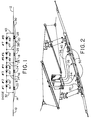
- Figure 1 illustrates first circuit 10 separated from a circuit 12 by the structure of this invention.
- the collector pantograph or shoe travels along first circuit 10 and then travels along entering transition clamp 14 while still receiving current from the first circuit.
- a series of runners are disposed having insulators therebetween.
- Runner A 16 is insulated from the transition clamp 14 by insulator 22.
- Runner B 18 is insulated from runner A 16 by insulation 24 and
- runner C 20 is insulated from runner B 18 by insulator 26.
- Runner C 20 extends to the leaving transition clamp 30 which clamp is insulated from runner C 20 by insulating piece 28. Leaving transition clamp 30 extends to second circuit 12.
- Transition clamps 14 and 30 are energized due to their direct connection to their associated power circuit.
- the entering transition clamp 14 is bolted or otherwise attached to the contact wire of first circuit 10, and the leaving transition clamp is likewise bolted or attached to the contact wire of second circuit 12.
- Runners A, B and C are energized by connections to a series of power circuits through jumper cables as will be described below.
- First jumper cable 32 attached to first circuit 10 which jumper 32 passes the current through first and second diodes 41 and 42, respectively, through second jumper cable 34 to runner A 16. No current can flow from second circuit 12 to main runner A because it is blocked by third and fourth diodes 43 and 44, respectively.
- the current from second circuit 12 cannot pass into first circuit 10 nor can the current from first circuit 10 pass to second circuit 12 because of the blocking nature of fifth and sixth diodes 45 and 46 preventing any current going in that direction.
- the current collector When the current collector is completely on runner B 18, it receives power from both the first and second circuits as described above.
- the current collector passes on to runner C 20 and is still on runner B, it receives power from first circuit 10 through third jumper 36 with current passing through first, second, third and fourth diodes, 41, 42, 43 and 44, respectively, but current from the first circuit 10 cannot flow into second circuit 12 due to the blocking action of seventh and eighth diodes 47 and 48.
- the current collector also receives power from second circuit 12 through third jumper 36 attached to runner B 18 through fifth and sixth diodes 46 and 45, respectively, directing power to runner C 20 over fourth jumper 38 and through the eighth and seventh diodes 48 and 47, respectively.
- Current from second circuit 12 cannot flow into first circuit 10 due to the blocking action of fourth and third diodes 44 and 43, respectively.
- all of the current flowing to the current collector is from second circuit 12 through fourth jumper 38 extending to runner C 20 through the eighth and seventh diodes 48 and 47.
- the fifth and sixth diodes 45 and 46 prevent current from first circuit 10 from flowing to runner C 20 and the fourth and third diodes 44 and 43 prevent current from second circuit 12 from flowing to first circuit 10.
- power is transmitted from the contact wire of second circuit 12 and from the fourth jumper cable 38 connected to runner C 20.
- Current in fourth jumper 38 flows from second circuit 12 through fifth jumper 40 and through eighth and seventh diodes 48 and 47.
- the current collector travels off main runner C onto the leaving transition clamp 30 and directly onto second circuit 12, it will receive all of its power from the trolley contact wires of second circuit 12.
- the arcing and burning of the prior art does not take place because the insulators 22, 24, 26 and 28 between the transition clamps and runners A, B and C are shorter than the length of the conducting strips of the pantograph current collectors or trolley pole/shoe current collectors.
- running/wearing surfaces 50 of runners A, B and C can easily be replaced when worn out without disturbing the tension in the contact wires by simply unbolting the wearing surface from the contact wires and removing it after first disconnecting the jumper cables.
- the new wearing surface can then be attached to the contact wires with the jumper wires then being reconnected.
- the suspension system can be attached only to the contact wires and does not have to be disturbed or dismantled during wear surface replacement procedures.
- This structure of this invention can be used with direct current overhead contact wire systems with voltages of 3,000 volts or less for electric railroads, light rail systems, trolley bus lines and underground mining operations. In underground mining operations, the structure of this invention is particularly useful because the absence of electrical arcing would help eliminate any explosions of gas which might be caused by such arcing.
- the structure of this invention can be installed on any type of contact wire system, either catenary or single contact wire. A suspension trapeze, as seen in Figure 2, with the attached parallelogram wires can be utilized for soft suspension.
- the structure of this invention can also be used in catenary or direct hard suspension systems in locations where contact wire support bars or tube-running surface construction is needed at junctions or turnouts.
- the structure of this invention can be pre-bent or field-bent for use in curved construction.
- the diode enclosure can be supported at the trapeze on a catenary messenger or at a cross-span pole; or if utilized in a mine or subway, on the wall or ceiling.
- the structure of this invention can be placed anywhere in a length of contact wire even if it is under constant tension, and it does not require an overlap to be installed.
- the structure of this invention further is subjected to much less electrical wear because no arcing will take place and even though it is subject to mechanical wear from the current collectors, the replacement of the separate wear surfaces, not being under tension, is easier. Also, since the runners can be of large cross-sectional area with a high profile, extreme wear can be tolerated before replacement is needed and should the structure wear down to a point where it breaks and fails, only the wearing surface will be affected and the contact wires will remain intact.
- an existing cut-in section insulator can be used to provide insulation in the contact wires and the wear surface conducting pieces can be attached under this insulator with the diode array enclosure placed on the existing section insulator support span.
- This arrangement would allow for the use of the structure at a section break using a non-bridging but arc-creating insulator or bridging insulator which would then become a constant-current non-bridging section insulator without the necessity of adding spanning supports.
Landscapes
- Engineering & Computer Science (AREA)
- Mechanical Engineering (AREA)
- Current-Collector Devices For Electrically Propelled Vehicles (AREA)
- Rectifiers (AREA)
- Materials For Medical Uses (AREA)
- Cable Accessories (AREA)
Claims (2)
- Gleichstrom nicht übertragender Streckentrenner zwischen einem ersten Stromkreis (10) einer ersten Oberleitung und einem zweiten Stromkreis (12) einer zweiten Oberleitung für ein elektrisch betriebenes Fahrzeug mit einem Stromabnehmer, wobei der Streckentrenner Mittel zur Verhinderung des Stromübertritts von einem der Stromkreise (10, 12) auf den anderen Stromkreis aufweist und wobei diese Mittel ein Eingangsstück, das mit dem ersten Stromkreis (10) und ein Ausgangsstück, das mit dem zweiten Stromkreis (12) verbunden ist, sowie zwei elektrisch leitende Laufschienen, die von dem Eingangsstück durch ein erstes Isolierstück, von dem Ausgangsstück durch ein zweites Isolierstück und voneinander durch ein drittes Isolierstück getrennt sind, aufweisen, wobei das erste Isolierstück durch eine erste Diodenkette und das zweite Isolierstück durch eine letzte Diodenkette, die beide entgegengesetzt zueinander geschaltet sind, überbrückt wird, dadurch gekennzeichnet, daß die Mittel zur Verhinderung des Stromübertritts eine weitere elektrisch leitende Laufschiene (18), die zwischen den beiden elektrisch leitenden Laufschienen (16, 20) und gegen diese isoliert angeordnet ist und zwei weitere, in entgegengesetzter Durchlaßrichtung geschaltete Diodenketten (43, 44; 45, 46), welche die weitere Laufschiene (18) mit den beiden Laufschienen (16, 20) verbindet, aufweisen, wobei die Dioden (41 bis 48) Stromübertritt von einem der beiden Stromkreise (10, 12) zu dem anderen Stromkreis (10, 12) verhindern, indem sie den Stromdurchgang durch diese Dioden (41 bis 48) blockieren und worin Lichtbogenbildung zwischen den Stromkreisen (10, 12) verhindert wird, wenn der Stromabnehmer von einer der elektrisch leitenden Laufschienen (16, 18, 20) zur nächsten übergeht, indem durch die weiteren Dioden (43 bis 46) an der weiteren elektrisch leitenden Laufschiene (18) Spannungsausgleich zwischen den Stromkreisen (10, 12) erfolgt, ohne daß zwischen dem ersten (10) und zweiten Stromkreis (12) eine elektrisch leitende Verbindung entsteht.
- Streckentrenner gemäß Patentanspruch 1, dadurch gekennzeichnet, daß er eine Eingangs-Endklemme (14) mit einem ersten und einem zweiten Ende, wobei das erste Ende der Eingangs-Endklemme (14) mit dem Kontaktdraht des ersten Stromkreises (10) verbunden ist; einen ersten Isolator (22) mit einem ersten und einem zweiten Ende, wobei der erste Isolator (22) kürzer ist als die Kontaktlänge des Stromabnehmers und wobei das erste Ende des ersten Isolators (22) mit dem zweiten Ende der Eingangs-Endklemme (14) verbunden ist; eine erste elektrisch leitende Laufschiene A (16) mit einem ersten und einem zweiten Ende, wobei das erste Ende mit dem zweiten Ende des ersten Isolators (22) verbunden ist; einen zweiten Isolator (24) mit einem ersten und einem zweiten Ende, wobei das erste Ende des zweiten Isolators (24) mit dem zweiten Ende der ersten Laufschiene A (16) verbunden ist; eine zweite elektrisch leitende Laufschiene B (18) mit einem ersten und einem zweiten Ende, wobei das erste Ende der zweiten Laufschiene B (18) mit dem zweiten Ende des zweiten Isolators (24) verbunden ist; einen dritten Isolator (26) mit einem ersten und einem zweiten Ende, wobei der dritte Isolator kürzer ist als die Kontaktlänge des Stromabnehmers und wobei das erste Ende des dritten Isolators (26) mit dem zweiten Ende der zweiten Laufschiene (18) verbunden ist; eine dritte elektrisch leitende Laufschiene C (20) mit einem ersten und einem zweiten Ende, wobei das erste Ende der dritten Laufschiene C (20) mit dem zweiten Ende des dritten Isolators (26) verbunden ist; einen vierten Isolator (28) mit einem ersten und einem zweiten Ende, wobei der vierte Isolator (28) kürzer ist als die Kontaktlänge des Stromabnehmers und wobei das erste Ende des vierten Isolators (28) mit dem zweiten Ende der dritten Laufschiene verbunden ist; eine Ausgangs-Endklemme (30) mit einem ersten und einem zweiten Ende, wobei das erste Ende mit dem zweiten Ende des vierten Isolators (28) und das zweite Ende mit dem Kontaktdraht des zweiten Stromkreises (12) verbunden ist; eine erste Kurzschlußbrücke (32) mit einem ersten und einem zweiten Ende, wobei das erste Ende mit dem Kontaktdraht des ersten Stromkreises (10) verbunden ist; eine Starkstromleitung, die sich von dem zweiten Ende der ersten Kurzschlußbrücke erstreckt; eine erste (41) und eine zweite Diode (42), die sich auf der Starkstromleitung des ersten Stromkreises (10) befindet, wobei die erste (41) und zweite Diode (42) so eingerichtet sind, daß sie Strom von dem ersten Stromkreis (10) durch die Dioden (41, 42) fließen lassen, daß sie jedoch jeden Strom in der Gegenrichtung blockieren; eine zweite Kurzschlußbrücke (34) mit einem ersten und einem zweiten Ende, wobei das erste Ende mit der Starkstromleitung verbunden ist und sich auf der Starkstromleitung hinter der ersten (41) und zweiten Diode (42) befindet und wobei das zweite Ende der zweiten Kurzschlußbrücke (34) mit der ersten Laufschiene A (16) verbunden ist; eine dritte (43) und vierte Diode (44), die sich auf der Starkstromleitung hinter der zweiten Kurzschlußbrücke (34) befinden, wobei die dritte (43) und vierte Diode (44) so angeordnet sind, daß sie Strom von dem ersten Stromkreis (10) hindurchtreten lassen, daß sie jedoch jeden Strom in der Gegenrichtung blockieren; eine dritte Kurzschlußbrücke (36) mit einem ersten und einem zweiten Ende, wobei das erste Ende mit der Starkstromleitung an einem Punkt hinter der dritten (43) und vierten Diode (44) verbunden ist und wobei das zweite Ende der dritten Kurzschlußbrücke (36) mit der zweiten Laufschiene B (18) verbunden ist; eine fünfte (45) und sechste Diode (46), die sich auf der Starkstromleitung hinter der dritten Kurzschlußbrücke (36) befinden, wobei die fünfte (45) und sechste Diode (46) so angeordnet sind, daß sie verhindern, daß Strom von dem zweiten Stromkreis (12) zu dem ersten Stromkreis (10) fließt, daß sie jedoch Strom von der Starkstromleitung zu der zweiten Laufschiene B (18) hindurchfließen lassen; eine vierte Kurzschlußbrücke (38) mit einem ersten und einem zweiten Ende, wobei das erste Ende der vierten Kurzschlußbrücke (38) mit einem Punkt auf der Starkstromleitung hinter der fünften (45) und sechsten Diode (46) verbunden ist und wobei das zweite Ende der vierten Kurzschlußbrücke (38) mit der dritten Laufschiene C (20) verbunden ist; eine siebte (47) und achte Diode (48), die sich auf der Starkstromleitung hinter der vierten Kurzschlußbrücke (38) befinden, und die so angeordnet sind, daß sie verhindern, daß Strom von dem ersten Stromkreis (10) zu dem zweiten Stromkreis (12) fließt, aufweist;
und wobei sich die Starkstromleitung hinter der siebten (47) und achten Diode (48) zu dem Kontaktdraht des zweiten Stromkreises (12) erstreckt; und wobei der Streckentrenner so ausgebildet ist, daß er Strom sowohl vom ersten (10) als auch vom zweiten Stromkreis (12) erhält und die erste (41), zweite (42), dritte und vierte Diode (44) so ausgebildet sind, daß sie verhindern, daß Strom von dem zweiten Stromkreis (12) zu dem ersten Stromkreis (10) fließt, selbst wenn die Laufschienen (16, 18, 20) durch den elektrischen Kontakt des Stromabnehmers, der so ausgebildet ist, daß er nie mehr als zwei Laufschienen (16, 18, 20) gleichzeitig überbrückt, und wobei die fünfte (45), sechste (46), siebte (47) und achte Diode (48) so ausgebildet sind, daß sie verhindern, daß Strom von dem ersten Stromkreis (10) zu dem zweiten Stromkreis (12) fließt.
Applications Claiming Priority (2)
| Application Number | Priority Date | Filing Date | Title |
|---|---|---|---|
| US58178090A | 1990-09-13 | 1990-09-13 | |
| US581780 | 1990-09-13 |
Publications (2)
| Publication Number | Publication Date |
|---|---|
| EP0475342A1 EP0475342A1 (de) | 1992-03-18 |
| EP0475342B1 true EP0475342B1 (de) | 1997-07-23 |
Family
ID=24326532
Family Applications (1)
| Application Number | Title | Priority Date | Filing Date |
|---|---|---|---|
| EP91115254A Expired - Lifetime EP0475342B1 (de) | 1990-09-13 | 1991-09-10 | Einen Gleichstrom nicht übertragenden Streckentrenner |
Country Status (3)
| Country | Link |
|---|---|
| EP (1) | EP0475342B1 (de) |
| AT (1) | ATE155750T1 (de) |
| DE (1) | DE69126932D1 (de) |
Families Citing this family (2)
| Publication number | Priority date | Publication date | Assignee | Title |
|---|---|---|---|---|
| US5341906A (en) * | 1993-10-15 | 1994-08-30 | White Paul F | Constant current wire crossing apparatus for overhead electrically operated vehicles |
| EP3922508B1 (de) | 2020-06-10 | 2024-10-09 | ALSTOM Holdings | Isolierträgeranordnung für eine fahrleitung zum antrieb eines elektrofahrzeugs, insbesondere einer strassenbahn oder eines fahrleitungsomnibusses sowie zugehörige fahrleitung |
Family Cites Families (5)
| Publication number | Priority date | Publication date | Assignee | Title |
|---|---|---|---|---|
| AT170462B (de) * | 1948-02-23 | 1952-02-25 | Karl Dipl Ing Wanisch | Elektrische Trennung von Kettenfahrleitungen an rasch befahrbaren Stellen |
| DE882250C (de) * | 1951-07-28 | 1953-07-06 | Licentia Gmbh | Trennstrecke zwischen zwei mit phasenverschobenen Spannungen betriebenen Fahrleitungsabschnitten |
| JPS4860206A (de) * | 1971-12-01 | 1973-08-23 | ||
| CH558267A (de) * | 1972-08-05 | 1975-01-31 | Pfisterer Karl Fabrik Elektote | Streckentrenner fuer oberleitungen. |
| AT377483B (de) * | 1983-04-07 | 1985-03-25 | Poechhacker & Co Elektrotechni | Gleis- oder streckentrenner |
-
1991
- 1991-09-10 AT AT91115254T patent/ATE155750T1/de not_active IP Right Cessation
- 1991-09-10 EP EP91115254A patent/EP0475342B1/de not_active Expired - Lifetime
- 1991-09-10 DE DE69126932T patent/DE69126932D1/de not_active Expired - Lifetime
Also Published As
| Publication number | Publication date |
|---|---|
| DE69126932D1 (de) | 1997-09-04 |
| EP0475342A1 (de) | 1992-03-18 |
| ATE155750T1 (de) | 1997-08-15 |
Similar Documents
| Publication | Publication Date | Title |
|---|---|---|
| JP4744605B2 (ja) | 剛体電車線用セクションインシュレータ | |
| RU2675765C2 (ru) | Энергосистема электрифицированной железной дороги без обратной последовательности во всем процессе и без сетей электропитания на интервалах | |
| US9845024B2 (en) | Gantry type movable catenary system at a railway crossing | |
| JP2017522229A (ja) | 電気鉄道におけるケーブルによる給電システム | |
| US7038125B2 (en) | Low-frequency de-icing of cableways | |
| US5117072A (en) | Constant current non-bridging section insulator | |
| KR20170043221A (ko) | 강체전차선용 지지클램프 | |
| EP0475342A1 (de) | Einen Gleichstrom nicht übertragenden Streckentrenner | |
| RU2485656C1 (ru) | Способ подогрева проводов контактной подвески | |
| KR20130087778A (ko) | 신축이음장치 | |
| US4187934A (en) | Section insulator for catenary systems | |
| JP2000118270A (ja) | 鉄道用超電導き電システム | |
| Mak | Adoption of overhead rigid conductor rail system in MTR extensions | |
| CN115782701B (zh) | 一种接触网锚段关节电连接系统 | |
| RU2307036C1 (ru) | Система тягового электроснабжения постоянного тока (варианты) | |
| RU2726592C1 (ru) | Способ электропитания управляемой вставки контактной сети переменного тока со съездом | |
| SU1425109A1 (ru) | Электрическа т гова сеть переменного тока | |
| DK2613962T3 (en) | Stretch separation device for a busbar conduit system | |
| US2001357A (en) | Electric traction | |
| CN115742886B (zh) | 一种apm枢轴道岔用供电轨系统 | |
| GB2328663A (en) | Electric current supply; sectioned conductor rail | |
| US2239582A (en) | Overhead line construction for trolley bus systems | |
| CN215322106U (zh) | 一种接触网交叉线索隔离装置 | |
| SU1323424A1 (ru) | Устройство дл плавки гололеда на контактной сети станции | |
| SU1675133A1 (ru) | Способ временного восстановлени контактной сети на двухпутном участке |
Legal Events
| Date | Code | Title | Description |
|---|---|---|---|
| PUAI | Public reference made under article 153(3) epc to a published international application that has entered the european phase |
Free format text: ORIGINAL CODE: 0009012 |
|
| AK | Designated contracting states |
Kind code of ref document: A1 Designated state(s): AT CH DE FR IT LI NL |
|
| 17P | Request for examination filed |
Effective date: 19920910 |
|
| 17Q | First examination report despatched |
Effective date: 19940422 |
|
| GRAG | Despatch of communication of intention to grant |
Free format text: ORIGINAL CODE: EPIDOS AGRA |
|
| GRAH | Despatch of communication of intention to grant a patent |
Free format text: ORIGINAL CODE: EPIDOS IGRA |
|
| GRAH | Despatch of communication of intention to grant a patent |
Free format text: ORIGINAL CODE: EPIDOS IGRA |
|
| GRAA | (expected) grant |
Free format text: ORIGINAL CODE: 0009210 |
|
| AK | Designated contracting states |
Kind code of ref document: B1 Designated state(s): AT CH DE FR IT LI NL |
|
| PG25 | Lapsed in a contracting state [announced via postgrant information from national office to epo] |
Ref country code: NL Free format text: LAPSE BECAUSE OF FAILURE TO SUBMIT A TRANSLATION OF THE DESCRIPTION OR TO PAY THE FEE WITHIN THE PRESCRIBED TIME-LIMIT Effective date: 19970723 Ref country code: AT Effective date: 19970723 |
|
| REF | Corresponds to: |
Ref document number: 155750 Country of ref document: AT Date of ref document: 19970815 Kind code of ref document: T |
|
| REG | Reference to a national code |
Ref country code: CH Ref legal event code: EP |
|
| REF | Corresponds to: |
Ref document number: 69126932 Country of ref document: DE Date of ref document: 19970904 |
|
| PGFP | Annual fee paid to national office [announced via postgrant information from national office to epo] |
Ref country code: FR Payment date: 19970910 Year of fee payment: 7 |
|
| ITF | It: translation for a ep patent filed | ||
| PG25 | Lapsed in a contracting state [announced via postgrant information from national office to epo] |
Ref country code: DE Effective date: 19971024 |
|
| ET | Fr: translation filed | ||
| REG | Reference to a national code |
Ref country code: CH Ref legal event code: NV Representative=s name: DR.-ING. ULRICH TIEMANN PATENTANWALT |
|
| NLV1 | Nl: lapsed or annulled due to failure to fulfill the requirements of art. 29p and 29m of the patents act | ||
| PLBE | No opposition filed within time limit |
Free format text: ORIGINAL CODE: 0009261 |
|
| STAA | Information on the status of an ep patent application or granted ep patent |
Free format text: STATUS: NO OPPOSITION FILED WITHIN TIME LIMIT |
|
| 26N | No opposition filed | ||
| PGFP | Annual fee paid to national office [announced via postgrant information from national office to epo] |
Ref country code: CH Payment date: 19981022 Year of fee payment: 8 |
|
| PG25 | Lapsed in a contracting state [announced via postgrant information from national office to epo] |
Ref country code: FR Free format text: LAPSE BECAUSE OF NON-PAYMENT OF DUE FEES Effective date: 19990531 |
|
| REG | Reference to a national code |
Ref country code: FR Ref legal event code: ST |
|
| PG25 | Lapsed in a contracting state [announced via postgrant information from national office to epo] |
Ref country code: LI Free format text: LAPSE BECAUSE OF NON-PAYMENT OF DUE FEES Effective date: 19990930 Ref country code: CH Free format text: LAPSE BECAUSE OF NON-PAYMENT OF DUE FEES Effective date: 19990930 |
|
| REG | Reference to a national code |
Ref country code: CH Ref legal event code: PL |
|
| PG25 | Lapsed in a contracting state [announced via postgrant information from national office to epo] |
Ref country code: IT Free format text: LAPSE BECAUSE OF NON-PAYMENT OF DUE FEES Effective date: 20050910 |