EP0475362B1 - Appareil de traitement d'images pour déterminer la proportion d'enlèvement de la sous-couleur - Google Patents
Appareil de traitement d'images pour déterminer la proportion d'enlèvement de la sous-couleur Download PDFInfo
- Publication number
- EP0475362B1 EP0475362B1 EP91115297A EP91115297A EP0475362B1 EP 0475362 B1 EP0475362 B1 EP 0475362B1 EP 91115297 A EP91115297 A EP 91115297A EP 91115297 A EP91115297 A EP 91115297A EP 0475362 B1 EP0475362 B1 EP 0475362B1
- Authority
- EP
- European Patent Office
- Prior art keywords
- max
- color
- ucr
- area
- circuit
- Prior art date
- Legal status (The legal status is an assumption and is not a legal conclusion. Google has not performed a legal analysis and makes no representation as to the accuracy of the status listed.)
- Expired - Lifetime
Links
- 238000004042 decolorization Methods 0.000 claims description 16
- 230000007704 transition Effects 0.000 claims 4
- 238000013459 approach Methods 0.000 claims 1
- 230000007423 decrease Effects 0.000 claims 1
- 230000008707 rearrangement Effects 0.000 description 12
- 238000000034 method Methods 0.000 description 10
- 230000007935 neutral effect Effects 0.000 description 10
- 238000006243 chemical reaction Methods 0.000 description 9
- 238000010586 diagram Methods 0.000 description 9
- 238000000926 separation method Methods 0.000 description 8
- 239000003086 colorant Substances 0.000 description 6
- 239000000654 additive Substances 0.000 description 4
- 230000000996 additive effect Effects 0.000 description 4
- 230000001052 transient effect Effects 0.000 description 3
- 230000000295 complement effect Effects 0.000 description 2
- 238000001514 detection method Methods 0.000 description 2
- 238000002474 experimental method Methods 0.000 description 2
- 230000002542 deteriorative effect Effects 0.000 description 1
- 230000000873 masking effect Effects 0.000 description 1
Images


Classifications
-
- H—ELECTRICITY
- H04—ELECTRIC COMMUNICATION TECHNIQUE
- H04N—PICTORIAL COMMUNICATION, e.g. TELEVISION
- H04N1/00—Scanning, transmission or reproduction of documents or the like, e.g. facsimile transmission; Details thereof
- H04N1/46—Colour picture communication systems
- H04N1/56—Processing of colour picture signals
- H04N1/60—Colour correction or control
- H04N1/6016—Conversion to subtractive colour signals
- H04N1/6022—Generating a fourth subtractive colour signal, e.g. under colour removal, black masking
- H04N1/6025—Generating a fourth subtractive colour signal, e.g. under colour removal, black masking using look-up tables
Definitions
- the present invention relates to an image processing apparatus for determining a rate of under color removal (UCR) for each of input color signals of yellow (Yi), magenta (Mi), and cyan (Ci) at each pixel, using an arithmetic function of a corresponding input color signal and a minimum value (Min) among the input color signals.
- the apparatus is capable of obtaining a color separation plate whose image quality is superb particularly at a shadow area.
- An image processing apparatus is also known from EP-A-0327278, which provides an under color removal for each color by calculating UCR color signals by arithmetic functions of the specific color signal and a minimum signal among the three color signals.
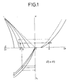
- FIGS. 1 and 2 One example illustrative of such a method will now be described with reference to FIGS. 1 and 2.
- a characteristic representing the relationship between an equivalent neutral density Dp and a black-printer value K to be reproduced on a print or printed matter a characteristic showing the relationship between an equivalent neutral density D 3 created by three forms or plates of Y (yellow), M (magenta) and C (cyan) and a halftone %, and a characteristic showing the relationship between Y, M, C with respect to the black-printer value K and an equivalent neutral density D 4 created by the black printer.
- a point C indicative of the equivalent neutral density obtained by Y, M, C forms subjected to the under color removal and the black printer can be determined from a black-printer value B with respect to a desired density A on the print.
- a point Q indicative of the equivalent neutral density obtained by Y, M and C subjected to the under color removal can be determined by setting K equal to 0.
- Yj, Mj and Cj each indicative of the equivalent neutral density, of Y, M and C as the three primary colors are inputted to a minimum value detection circuit 42 and supplied as address data to look-up tables 46Y, 46M and 46C.
- the minimum value detection circuit 42 serves to determine a signal indicative of the minimum value of the equivalent neutral density, which is selected from Yj, Mj and Cj each indicative of the equivalent neutral density, i.e., the minimum value of Yj, Mj and Cj each indicative of the equivalent neutral density.
- the minimum value thus determined is applied to a black-printer generating circuit 44 used to generate a black-printer value.
- the output KS of the black-printer generating circuit 44 is supplied to each of the look-up tables 46Y, 46M and 46C as address data.
- Each of the look-up tables 46Y, 46M and 46C is used to store therein data about the rate of the UCR, which has previously been determined by an experiment.
- the look-up tables 46Y, 46M and 46C respectively output UR Y , UR M and UR C each indicative of the rate of the UCR in accordance with the input KS as the address data and Yj, KS and Mj, and KS and Cj.
- the above-described method has, however, the problem that noise independently produced for each color at each of the input signals exerts an influence on other color forms or plates, thereby greatly deteriorating the quality of an image of each color separation form or plate at a shadow area in particular.
- FIG. 10 is an image processing apparatus according to one embodiment of the present invention.
- Each of color signals delivered from a photoelectric converting device (not shown) using, for example, a CCD is inputted to the image processing apparatus 10 as an input signal.
- symbols Yi, Mi and Ci are of color input signals indicative of yellow, magenta and cyan, respectively.
- the color input signals are supplied to a color correction circuit 12, a rearrangement circuit 20 and a UCR-rate calculation circuit 22.
- the color correction circuit 12 performs color correction on the color input signals based on signals delivered from the re-arrangement circuit 20.
- the re-arrangement circuit 20 is used to rearrange the input signals Yi, Mi and Ci in order of their levels or magnitude.
- a gradation or tone conversion circuit 14 is a circuit having a table for correcting gradation or tones.
- the color correction circuit 12 is activated to electrically process a Y color.
- the input signals Yi, Mi and Ci are supplied to the re-arrangement circuit 20.
- the re-arrangement circuit 20 is constructed as shown in FIG. 5.
- the signals Yi, Mi and Ci, which are inputted to the re-arrangement circuit 20, are delivered to corresponding comparators 72, 74 and 76, where the levels of these input signals Yi, Mi and Ci are compared with one another.
- the comparator 72 compares Yi and Mi in level
- the comparator 74 compares the level of Mi with that of Ci.
- the comparator 76 compares the level of Ci with that of Yi.
- the outputs of the comparators 72, 74 and 76 are inputted to inputs A 1 to A 3 , respectively, of a logic circuit 78.
- a logical combination is thus defined as given in Table 1 shown below.
- the outputs B 1 , B 2 and B 3 of the logic circuit 78 are inputted to selectors 80, 82 and 84 respectively.
- the selector 80 selects, i.e., outputs one indicative of the Max color out of the input signals Yi, Mi and Ci supplied thereto.
- the selector 82 outputs the other indicative of the Mid color out of these signals applied thereto.
- the selector 84 outputs the remaining one indicative of the Min color out of these signals supplied thereto.
- the logic circuit 78 outputs a primary color factor selection signal H 1 as B 1 and a secondary color factor selection signal H 2 as B 3 .
- the color correction circuit 12 may perform an arithmetic operation on only factors of the two hues subjected to hue discrimination or determination.
- the two hues are the Max color and the complementary color of the Min color of the three primary colors. Therefore, the two hues can be achieved by the following Table 2 showing the relation between H 1 , H 2 and factors to be selected. TABLE 2 H 1 Factors to be selected H 2 Factors to be selected 0 A Y/Y 0 A Y/B 1 A Y/M 1 A Y/G 2 A Y/C 2 A Y/R
- a i/j is indicative of a color correction factor
- its suffix represents a correction factor of an i form or plate with respect to a hue j.
- the intensity of each of the two hues, i.e., H 1 and H 2 to be color-corrected is calculated from each of the following equations represented by I 1 and I 2 .
- I 1 (Max value) - (Mid value)
- I 2 (Mid value) - (Min value)
- I 1 represents the saturation of Y
- I 2 shows the saturation of R complementary to C.
- a value to be corrected with respect to each input signal can be determined by the following equation obtained by multiplying the intensity I 1 by a factor A Y/H 1 and the intensity I 2 by a factor A Y/H 2 respectively and adding the two together.
- ⁇ Y I 1 ⁇ A Y/H 1 +I 2 ⁇ A Y/H 2
- An under color removal (hereinafter be abbreviated "UCR") circuit 16 is used to remove an under color.
- the UCR-rate calculation circuit 22 is used to calculate the rate of UCR with respect to each color.
- a density vs. halftone % conversion circuit 18 is used to convert each of color signals into a signal indicative of a halftone-dot area percentage, i.e., dot percentage for printing.
- a color original image is photoelectrically scanned to produce a color separation signal, which is subjected to a fundamental masking arithmetic process. Then, digitized signals Yi, Mi and Ci are inputted to the color correction circuit 12 and simultaneously supplied to the re-arrangement circuit 20 as well.
- the re-arrangement circuit 20 compares the levels of the input signals Yi, Mi and Ci with one another. Thereafter, the outputs of the re-arrangement circuit 20 are supplied to the color correction circuit 12.
- the color correction circuit 12 performs a color correction process so as to output signals Y 1 , M 1 and C 1 subjected to the color correction and a black-printer signal K 1 .
- the signals which have been subjected to the color correction by the color correction circuit 12, are inputted to the tone conversion circuit 14, where they are subjected to tone conversion.
- the signals subjected to the tone conversion are then inputted to the UCR circuit 16.
- the UCR circuit 16 is supplied with output signals (each indicative of the rate of under color removal) Y U , M U and C U from the UCR-rate calculation circuit 22, and with values I Y , I M and I C each providing the intensity of UCR.
- the UCR circuit 16 performs an under color removal process for each color.
- the respective signals subjected to the under color removal process by the UCR circuit 16 are supplied to the density vs. halftone % conversion circuit 18 from which Y 0 , M 0 , C 0 and K 0 are outputted as platemaking signals.
- the UCR circuit 16 will now be described with reference to FIG. 6.
- the UCR circuit 16 comprises sub UCR circuits 24, 26, 28 which correspond to colors of Y (yellow), M(magenta), and C(cyan), respectively.
- the UCR circuit 24 corresponding to the Y is supplied with, for example, Y 2 of the outputs of the tone conversion circuit 14 and Y U of the outputs of the UCR-rate calculation circuit 22 so as to hold these Y 2 and Y U in a look-up table as address data. Then, the rate of the UCR, which has previously been determined by experiments, is outputted from the look-up table. Thereafter, the rate of the UCR is multiplied by the value I Y providing the UCR intensity, and the result of its multiplication is subtracted from Y 2 , thereby making it possible to obtain Y 3 as the output of the UCR circuit 24.
- the UCR circuits 26 and 28 are supplied with M 2 from the tone conversion circuit 14 and M U from the UCR-rate calculation circuit 22, and with C 2 from the tone conversion circuit 14 and C U from the UCR-rate calculation circuit 22, respectively so as to hold these data M 2 , M U and C 2 , C U in corresponding look-up tables. Then, the rate of the UCR is outputted from each of the two look-up tables, and thereafter multiplied by each of the values I M and I C providing the UCR intensity. Then, the two results of their multiplication are subtracted from M 2 and C 2 respectively, thereby making it possible to determine M 3 and C 3 .
- the respective values I Y , I M and I C each indicative of the UCR intensity are of externally-set values.
- the outputs Y U , M U and C U each indicative of the rate of the under color removal, which are inputted to the UCR circuit 16, are determined by the maximum and minimum values Max and Min of each of the input signals Yi, Mi, Ci and respective functions F Y , F M and F C of the input signals Yi, Mi and Ci.
- each of the functions F Y , F M and F C is set up as a look-up table.
- Each of the outputs Y U , M U and C U indicative of the rate of the UCR is equivalent to an output KS shown in FIG. 2.
- the under color removal process is carried out based on Yi, Mi, Ci each indicative of an equivalent neutral density and the output KS.
- a signal corresponding to the output KS as a black-printer value is determined from the input signals Yi, Mi, Ci and their maximum and minimum values.
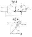
- This circuit comprises a look-up table 32, additive circuits 36, 40, and multiplication circuits 34, 38.
- the look-up table 32 is supplied as inputs thereof with the maximum value Max and the minimum value Min from the re-arrangement circuit 20 shown in FIG. 3. Then, the output of the look-up table 32 is multiplied by an input signal Yi in the multiplication circuit 34, and subtracted from a signal 1 in the additive circuit 36.
- the output of the additive circuit 36 is multiplied by the minimum value Min in the multiplication circuit 38.
- the outputs of the multiplication circuits 34 and 38 are added together in the additive circuit 40 so as to generate Y U therefrom.
- the remaining outputs M U and C U can be processed in the same manner as described above.
- the rate of UCR for each color is determined from the maximum and minimum values of the three primary colors and the respective color signals without using only a signal determined from the minimum value of values of input signals indicative of the three primary colors. Therefore, noise independently produced for each color at each of the input signals can be prevented from appearing at other color separation forms or plates. As a consequence, the quality of an image of each color separation plate can be improved at the shadow area in particular.
Landscapes
- Engineering & Computer Science (AREA)
- Multimedia (AREA)
- Signal Processing (AREA)
- Color Image Communication Systems (AREA)
- Color, Gradation (AREA)
- Facsimile Image Signal Circuits (AREA)
Claims (4)
- Un appareil de traitement d'images destiné à déterminer un taux de suppression de couleur de fond (UCR) pour chacun des signaux de couleurs d'entrée pour le jaune (Yi), le magenta (Mi) et le cyan (Ci) à chaque pixel, en utilisant une fonction arithmétique d'un signal de couleur d'entrée correspondant et une valeur minimale (Min) parmi les signaux de couleurs d'entrée,
caractérisé en ce qu'il comprenddes moyens (20, 80) pour déterminer une valeur maximale (Max) parmi les signaux de couleurs d'entrée (Yi, Mi, Ci) ; etdes moyens (22) pour déterminer le taux de suppression de couleur de fond (UCR) pour chaque couleur : Yu, Mu et Cu, sur la base des signaux de couleurs d'entrée, des valeurs minimales et des valeurs maximales, respectivement Yi, Mi, Ci, Max, Min, et d'un paramètre t, ces taux de suppression de couleur de fond (UCR) Yu, Mu et Cu étant donnés par les équations suivantes :


 et la fonction Ft (Max, Min) étant définie de façon que t varie de 0 à 1 conformément à la position d'un jeu des valeurs Max et Min dans un plan Max-Min.
 - Un appareil de traitement d'images selon la revendication 1, dans lequel la fonction Ft est définie par référence à une table, de façon que t soit inférieur ou égal à 1 dans une région sombre représentant une région sombre dans une image, qui est définie par une ligne limite prédéterminée dans le plan Max-Min, et t soit égal à 0 dans la région autre que la région sombre.
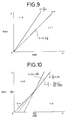
- Un appareil de traitement d'images selon la revendication 1, dans lequel la fonction Ft est définie de façon que :t soit égal à 1 lorsque les signaux de couleurs d'entrée correspondent à une région de gris dans laquelle les valeurs Max et Min sont presque mutuellement égales ;t varie de 0 à 1 lorsque les signaux de couleurs d'entrée correspondent à une région de transition entre la région de gris et une région autre que du gris, et diminue dans la plage 1 > t >0 lorsque la position du jeu de valeurs de Max et Min s'éloigne de la région de gris et s'approche d'une ligne limité prédéterminéee qui définit la région de transition dans le plan Max-Min ; ett soit égal à 0 lorsque les signaux de couleurs d'entrée correspondent à la région autre que la région de gris, dans laquelle le jeu de valeurs de Max et Min se trouve sur la ligne limite ou à l'extérieur de la région de transition.
- Un appareil de traitement d'images selon la revendication 3, dans lequel la région de gris, la région de transition et la région autre que la région de gris sont définies dans une région sombre dans le plan Max-Min.
Applications Claiming Priority (2)
| Application Number | Priority Date | Filing Date | Title |
|---|---|---|---|
| JP2245608A JP2815474B2 (ja) | 1990-09-14 | 1990-09-14 | 画像処理装置 |
| JP245608/90 | 1990-09-14 |
Publications (3)
| Publication Number | Publication Date |
|---|---|
| EP0475362A2 EP0475362A2 (fr) | 1992-03-18 |
| EP0475362A3 EP0475362A3 (en) | 1992-12-09 |
| EP0475362B1 true EP0475362B1 (fr) | 1996-12-27 |
Family
ID=17136240
Family Applications (1)
| Application Number | Title | Priority Date | Filing Date |
|---|---|---|---|
| EP91115297A Expired - Lifetime EP0475362B1 (fr) | 1990-09-14 | 1991-09-10 | Appareil de traitement d'images pour déterminer la proportion d'enlèvement de la sous-couleur |
Country Status (4)
| Country | Link |
|---|---|
| US (1) | US5255084A (fr) |
| EP (1) | EP0475362B1 (fr) |
| JP (1) | JP2815474B2 (fr) |
| DE (1) | DE69123800T2 (fr) |
Families Citing this family (5)
| Publication number | Priority date | Publication date | Assignee | Title |
|---|---|---|---|---|
| JP2815474B2 (ja) * | 1990-09-14 | 1998-10-27 | 富士写真フイルム株式会社 | 画像処理装置 |
| US5305119A (en) * | 1992-10-01 | 1994-04-19 | Xerox Corporation | Color printer calibration architecture |
| US5459590A (en) * | 1993-04-08 | 1995-10-17 | Linotype-Hell Ag | Method and apparatus for freely selectable substitution of the achromatic part in multi color printing with the black ink |
| JP4018755B2 (ja) * | 1995-08-22 | 2007-12-05 | 富士フイルム株式会社 | 色信号変換用トーンカーブ作成方法及び装置 |
| US6031630A (en) * | 1998-05-05 | 2000-02-29 | Hewlett-Packard Company | Method and apparatus for undercolor removal during page pipeline processing |
Family Cites Families (10)
| Publication number | Priority date | Publication date | Assignee | Title |
|---|---|---|---|---|
| DE3109190C2 (de) * | 1981-03-11 | 1985-07-11 | Dr.-Ing. Rudolf Hell Gmbh, 2300 Kiel | Verfahren zur Reproduktion farbiger Vorlagen im Vierfarbendruck unter Farbrücknahme |
| JPS60249469A (ja) * | 1984-05-25 | 1985-12-10 | Fuji Xerox Co Ltd | 墨信号分離装置 |
| JPS6250014A (ja) * | 1986-06-06 | 1987-03-04 | Hitachi Cable Ltd | 複合線条体の製造方法 |
| JPS63151263A (ja) * | 1986-12-16 | 1988-06-23 | Victor Co Of Japan Ltd | 感熱記録装置の色補正回路 |
| US4839722A (en) * | 1987-10-30 | 1989-06-13 | Colorocs Corporation | Method and apparatus for providing improved color correction in a subtrative color printing system |
| EP0327278B1 (fr) * | 1988-01-29 | 1994-05-04 | Canon Kabushiki Kaisha | Dispositif pour la formation d'images en couleurs et procédé et dispositif de traitement d'images en couleurs |
| JPH01284074A (ja) * | 1988-05-10 | 1989-11-15 | Fuji Xerox Co Ltd | カラー記録方式 |
| JPH02118680A (ja) * | 1988-10-28 | 1990-05-02 | Fuji Xerox Co Ltd | 画像形成装置の下色除去方式 |
| EP0409474B1 (fr) * | 1989-07-17 | 1995-11-29 | Matsushita Electric Industrial Co., Ltd. | Appareil pour la formation d'images en couleur |
| JP2815474B2 (ja) * | 1990-09-14 | 1998-10-27 | 富士写真フイルム株式会社 | 画像処理装置 |
-
1990
- 1990-09-14 JP JP2245608A patent/JP2815474B2/ja not_active Expired - Fee Related
-
1991
- 1991-09-05 US US07/755,373 patent/US5255084A/en not_active Expired - Fee Related
- 1991-09-10 EP EP91115297A patent/EP0475362B1/fr not_active Expired - Lifetime
- 1991-09-10 DE DE69123800T patent/DE69123800T2/de not_active Expired - Fee Related
Also Published As
| Publication number | Publication date |
|---|---|
| JP2815474B2 (ja) | 1998-10-27 |
| DE69123800T2 (de) | 1997-04-17 |
| US5255084A (en) | 1993-10-19 |
| EP0475362A3 (en) | 1992-12-09 |
| JPH04124666A (ja) | 1992-04-24 |
| EP0475362A2 (fr) | 1992-03-18 |
| DE69123800D1 (de) | 1997-02-06 |
Similar Documents
| Publication | Publication Date | Title |
|---|---|---|
| US5483361A (en) | Color image copying with resolution control | |
| US5331442A (en) | Identification of graphic and character areas in color image processor | |
| EP0495914B2 (fr) | Methode demi-teinte numerique de couleurs par diffusion d'erreur vectorielle | |
| US5729360A (en) | Color image processing method and system | |
| US5886797A (en) | Method and apparatus for controlling a spatial filtering process based on characteristics of image data | |
| US5075767A (en) | Digital color image signal processing apparatus | |
| US5781709A (en) | Method of and apparatus for generating proof | |
| US6002806A (en) | Method of and apparatus for correcting color | |
| US6734899B1 (en) | Method of establishing color correction functions | |
| JP2906974B2 (ja) | カラー画像処理方法および装置 | |
| US5255084A (en) | Image processing apparatus for determining rates of OCR for every colors by functions of respective color signals | |
| JPH04335771A (ja) | 色修正装置 | |
| JPH07152904A (ja) | 画像処理装置 | |
| Jiang et al. | Color halftoning based on neugebauer primary area coverage | |
| US7012719B1 (en) | Sign sensitive aperture correction system and method | |
| JPH07203231A (ja) | カラー画像処理装置 | |
| JP3728025B2 (ja) | 画像処理方法及び装置 | |
| US20040234134A1 (en) | Image processing apparatus and image processing method | |
| JP3251617B2 (ja) | 画像処理装置および方法 | |
| JPH0581418A (ja) | 彩度調整装置 | |
| JPH09130622A (ja) | 画像処理装置 | |
| JP2996500B2 (ja) | 画像処理装置 | |
| JP3190527B2 (ja) | カラー画像処理装置 | |
| JP2618893B2 (ja) | カラー画像処理装置 | |
| JP3305013B2 (ja) | 画像処理装置およびその方法 |
Legal Events
| Date | Code | Title | Description |
|---|---|---|---|
| PUAI | Public reference made under article 153(3) epc to a published international application that has entered the european phase |
Free format text: ORIGINAL CODE: 0009012 |
|
| 17P | Request for examination filed |
Effective date: 19910910 |
|
| AK | Designated contracting states |
Kind code of ref document: A2 Designated state(s): DE FR GB |
|
| PUAL | Search report despatched |
Free format text: ORIGINAL CODE: 0009013 |
|
| AK | Designated contracting states |
Kind code of ref document: A3 Designated state(s): DE FR GB |
|
| 17Q | First examination report despatched |
Effective date: 19950210 |
|
| GRAH | Despatch of communication of intention to grant a patent |
Free format text: ORIGINAL CODE: EPIDOS IGRA |
|
| GRAH | Despatch of communication of intention to grant a patent |
Free format text: ORIGINAL CODE: EPIDOS IGRA |
|
| GRAA | (expected) grant |
Free format text: ORIGINAL CODE: 0009210 |
|
| AK | Designated contracting states |
Kind code of ref document: B1 Designated state(s): DE FR GB |
|
| REF | Corresponds to: |
Ref document number: 69123800 Country of ref document: DE Date of ref document: 19970206 |
|
| ET | Fr: translation filed | ||
| PLBE | No opposition filed within time limit |
Free format text: ORIGINAL CODE: 0009261 |
|
| STAA | Information on the status of an ep patent application or granted ep patent |
Free format text: STATUS: NO OPPOSITION FILED WITHIN TIME LIMIT |
|
| 26N | No opposition filed | ||
| REG | Reference to a national code |
Ref country code: GB Ref legal event code: IF02 |
|
| PGFP | Annual fee paid to national office [announced via postgrant information from national office to epo] |
Ref country code: FR Payment date: 20040826 Year of fee payment: 14 |
|
| PGFP | Annual fee paid to national office [announced via postgrant information from national office to epo] |
Ref country code: GB Payment date: 20040901 Year of fee payment: 14 |
|
| PGFP | Annual fee paid to national office [announced via postgrant information from national office to epo] |
Ref country code: DE Payment date: 20041027 Year of fee payment: 14 |
|
| PG25 | Lapsed in a contracting state [announced via postgrant information from national office to epo] |
Ref country code: GB Free format text: LAPSE BECAUSE OF NON-PAYMENT OF DUE FEES Effective date: 20050910 |
|
| PG25 | Lapsed in a contracting state [announced via postgrant information from national office to epo] |
Ref country code: DE Free format text: LAPSE BECAUSE OF NON-PAYMENT OF DUE FEES Effective date: 20060401 |
|
| GBPC | Gb: european patent ceased through non-payment of renewal fee |
Effective date: 20050910 |
|
| PG25 | Lapsed in a contracting state [announced via postgrant information from national office to epo] |
Ref country code: FR Free format text: LAPSE BECAUSE OF NON-PAYMENT OF DUE FEES Effective date: 20060531 |
|
| REG | Reference to a national code |
Ref country code: FR Ref legal event code: ST Effective date: 20060531 |