EP0475462A1 - Procédé de fonctionnement d'une machine à laver à tambour et machine prévue à cet effet - Google Patents
Procédé de fonctionnement d'une machine à laver à tambour et machine prévue à cet effet Download PDFInfo
- Publication number
- EP0475462A1 EP0475462A1 EP19910118837 EP91118837A EP0475462A1 EP 0475462 A1 EP0475462 A1 EP 0475462A1 EP 19910118837 EP19910118837 EP 19910118837 EP 91118837 A EP91118837 A EP 91118837A EP 0475462 A1 EP0475462 A1 EP 0475462A1
- Authority
- EP
- European Patent Office
- Prior art keywords
- drum
- section
- during
- washing machine
- wetting
- Prior art date
- Legal status (The legal status is an assumption and is not a legal conclusion. Google has not performed a legal analysis and makes no representation as to the accuracy of the status listed.)
- Granted
Links
Images


Classifications
-
- D—TEXTILES; PAPER
- D06—TREATMENT OF TEXTILES OR THE LIKE; LAUNDERING; FLEXIBLE MATERIALS NOT OTHERWISE PROVIDED FOR
- D06F—LAUNDERING, DRYING, IRONING, PRESSING OR FOLDING TEXTILE ARTICLES
- D06F37/00—Details specific to washing machines covered by groups D06F21/00 - D06F25/00
- D06F37/02—Rotary receptacles, e.g. drums
- D06F37/04—Rotary receptacles, e.g. drums adapted for rotation or oscillation about a horizontal or inclined axis
- D06F37/06—Ribs, lifters, or rubbing means forming part of the receptacle
- D06F37/065—Ribs, lifters, or rubbing means forming part of the receptacle ribs or lifters having means for circulating the washing liquid
-
- D—TEXTILES; PAPER
- D06—TREATMENT OF TEXTILES OR THE LIKE; LAUNDERING; FLEXIBLE MATERIALS NOT OTHERWISE PROVIDED FOR
- D06F—LAUNDERING, DRYING, IRONING, PRESSING OR FOLDING TEXTILE ARTICLES
- D06F35/00—Washing machines, apparatus, or methods not otherwise provided for
- D06F35/005—Methods for washing, rinsing or spin-drying
- D06F35/006—Methods for washing, rinsing or spin-drying for washing or rinsing only
-
- Y—GENERAL TAGGING OF NEW TECHNOLOGICAL DEVELOPMENTS; GENERAL TAGGING OF CROSS-SECTIONAL TECHNOLOGIES SPANNING OVER SEVERAL SECTIONS OF THE IPC; TECHNICAL SUBJECTS COVERED BY FORMER USPC CROSS-REFERENCE ART COLLECTIONS [XRACs] AND DIGESTS
- Y02—TECHNOLOGIES OR APPLICATIONS FOR MITIGATION OR ADAPTATION AGAINST CLIMATE CHANGE
- Y02B—CLIMATE CHANGE MITIGATION TECHNOLOGIES RELATED TO BUILDINGS, e.g. HOUSING, HOUSE APPLIANCES OR RELATED END-USER APPLICATIONS
- Y02B40/00—Technologies aiming at improving the efficiency of home appliances, e.g. induction cooking or efficient technologies for refrigerators, freezers or dish washers
Definitions
- the invention relates to a method for operating a drum washing machine and a drum washing machine therefor with a horizontally rotatably mounted washing drum with a perforated drum jacket and with drivers arranged therein, which have scooping devices that are open towards the interior thereof, and with an automatically controlled washing program that has a wetting section with a drum speed of at most 30 min- 1 , a rinse section with a drum speed of at most 60 min- 1 , a rinse section and a spin section.
- Such a drum washing machine is known from DE-OS 37 12 118. It is operated continuously in a wetting phase, preferably at a laundry drum speed of 27 min- 1 . Compared to drum washing machines, the drum of which is also operated during the wetting phase at the usual washing speed of 55 min- 1 , for example, the wetting of the laundry can be intensified to such a degree that even with the lowest possible water level just above the lower apex of the laundry drum in a relatively short time Time is moistened homogeneously.
- drum washing machines on the market are already provided with a hidden device for increasing the water level.
- the originally intended saving effect in relation to the amount of water and energy used is given up again.
- the invention is therefore based on the object of operating a drum washing machine of the known type in such a way that the laundry is homogeneously wetted with absolute certainty and in the shortest possible time even at a very low water level and is more effectively freed from dirt during the rinse section.
- the object is achieved in that the drum is driven intermittently during the wetting section with at most 30%, preferably 25%, duty cycle and only in the scooping direction during the rinsing section and during the rinsing section alternately in the scooping direction and in the emptying direction and during the spinning section only in the emptying direction.
- the irrigation effect described in DE-OS 37 12 118 is responsible for the homogeneous moistening of the laundry, but that during washing pauses between the drum rotation intervals, the lye rained on the laundry during a seeping process Can wet laundry even more intensely.
- the dirt detaching effect is increased during the clear wash section, as will be explained further below.
- the drum is driven alternately in the direction of scooping and in the direction of emptying during the wetting section.
- the change in the drum rotation direction creates a pumping effect of the alkali within the suds container and the laundry drum and such a shifting of the Laundry that during the subsequent scooping and sprinkling process again dry laundry parts are exposed to the lye rain.
- a further development of the method according to the invention prefers the duty cycle during an interval of the drum drive with approximately 4 s and the downtime of the drum with approximately 12 s. 4 s running time of the drum convey enough lye over the laundry, which is seeped out by the lye during 12 s drum standstill.
- a further development of the method is particularly advantageous, in which the drum drive is switched on during the wetting section for the first time after a lye level has been reached at which the scooping devices are immersed in the lye. This can prevent the laundry that has not yet been wetted from being layered dry in the laundry for too long and thereby being subject to increased abrasion.
- the wetting section of the method according to the invention is advantageously a maximum of 3 minutes long.
- a full laundry load of, for example, 4.5 kg can be moistened homogeneously within this time.
- the drum is also intermittently during the wetting section with a maximum of 30%, preferably 25% duty cycle and only alternately in the scooping direction during the clear washing section and during the rinsing section alternately in the scooping direction and in the emptying direction as well only driven in the direction of emptying during the spinning section, but the rinse section has at least two cycles, which comprises a washer-extracting phase in which the washing drum is rotated in the emptying direction of rotation at a speed of up to 300 min- 1 , and a reversing phase in which the washing drum alternates with a washing speed of un is rotated approximately 55 min- 1 , the direction of scoop being maintained for less than the direction of emptying.
- a special washing effect can be achieved in such a way, that the alkali level in the suds container outside the laundry drum is increased during the spin cycle by expelling the alkali from the laundry, while in the subsequent reversing phase almost the whole Lye amount is taken up again in the laundry drum and in the laundry, so that an almost complete exchange of the washing liquor bound by the laundry takes place.
- This exchange also means that dispersed and bound dirt particles are driven out of the laundry more intensively.
- the scooping devices of all drivers can point in a common scooping direction. This simplifies the construction of the laundry drum and is particularly well suited if all the desired wetting and washing effects can be achieved by less complex control means.
- each driver contains at least two mutually sealed chambers of different volumes and point their associated scooping devices in different scooping directions. As a result, a variety of wetting and washing effects can be achieved using a few different rotation rhythms.
- the washer-extractor phase of a drum washing machine according to the method of claim 5 advantageously lasts about 10 s, while the reversing phase takes about 80 s.
- the effect described above can be optimized by the fact that the duration of the scoop rotation direction and the duration of the emptying rotation direction within a reversing phase are approximately 1: 3.
- a special design of the drum washing machine according to the invention results from the design of the drivers in the form of a saddle roof, the roof surface on the side of the scoop being unperforated, the other roof surface being perforated in the area of the roof top and unperforated in the area of the roof base.
- Such a form of the carrier has proven to be particularly well suited for the scooping action and the sprinkling of the laundry.
- the tub 1 in FIG. 1 contains in its upper area a filling opening 2 for detergent introduced from a detergent dispenser 3 together with feed water.
- the bottom of the lye container 1, which is kept as close as possible to the drum 4, has a recess 5 in which the heating elements 6 required for heating the lye are arranged.
- a recess 5 At the deepest point of the recess 5 there is an outlet opening 7 which is kept closed by a closure body 8 as long as a drain pump (not shown) does not suck on the drain line 9.
- This closure body 8 has the task of keeping the space below the drain opening 7 closed as long as there is detergent required for washing the laundry inside the tub.
- the drum washing machine known from DE-OS 37 12 118 therefore has scooping devices 12 on the circumference in the area of the drivers 11, which when rotating the drum, e.g. in the direction of arrow 13, from the lye stock standing in the recess 5, the respective intermediate storage space, here the driver 11, can fill.
- this scooped amount of water is first temporarily stored and only released into the drum interior via outlet openings in the intermediate storage space when the intermediate storage space is a certain height in the region below or above the horizontal drum axis 15, but preferably above that lying in the drum 4, completely wetted laundry 10 has reached.
- the arrows 14 indicate the manner in which the water so raised rains over the laundry 10.
- the driver 11 can be divided into bulkheads 23 by bulkheads 23 according to FIG. 2. Here they are similar to the drivers in Fig. 6 of DE-OS 37 12 118.
- the chambers 25 distributed along the driver in turn, like the known driver, have alternating ladles 20 pointing in one and in the other direction of rotation as scooping devices for the drivers.
- the roof-shaped part of the driver only has flood holes 17 on the roof surface opposite the ladle 20, through which raised lye can be rinsed.
- the flood holes are arranged in each of these roof areas, but only in the vicinity of the roof top, so that sufficient lye can accumulate in the solid angle at the foot of this roof area for lifting up.
- the right ladle scoops 20 lye into the chamber 25.
- Fig. 4 shows a driver with only a single chamber 41, the scoops of which are directed in one direction only. Accordingly, this chamber can only scoop in one direction of rotation.
- the scoops 20 facing away from the respective direction of rotation and the associated chambers of all exemplary embodiments of drivers pump lye out of the laundry drum again and convey it into the space between the drum and the tub. This promotes the exchange between the lye in the laundry and the free lye. This results in a better washing effect because dirt detached from the laundry can be washed out of the laundry more quickly.
- the laundry drum shown in FIG. 5 rotates in the direction of scooping according to arrow 13.
- the scoops 20 scoop the lye from the tub into the driver 11 and, on the other hand, the flood holes 16 also from the space between the drum 4 and the tub of liquor onto the unperforated roof surfaces 26 of the drivers 11.
- the driver located further up shows that lye drawn according to the arrow 18 flows from the outside of the roof surface 26 onto the laundry lying below (not shown in FIGS. 5 and 6) and shortly thereafter also drawn lye through the flood holes 17 according to the arrows 14 from the driver 11 onto the Laundry is raining. It can therefore be seen from this that the wetting effect is greater than in the subject of DE-OS 37 12 118.
- the laundry drum shown in FIG. 6 rotates according to arrow 19 in the direction of emptying.
- This lye essentially comes from the wet laundry according to arrow 21 and is also sucked through the flood holes 16 in the drum jacket from the space between the drum and the tub at drum speeds of up to about 60 min- 1 .
- the centrifugal force predominates, so that moisture is only sucked in from the inside of the drum.
- the laundry drum is driven at intervals with a maximum of 30% duty cycle.
- Laundry drums the drivers of which are designed according to FIGS. 2 and 3, can be driven reversing.
- the reversing rhythm can also be distributed uniformly, e.g. 3 s anticlockwise rotation, 9 s pause, 3 s clockwise rotation and 9 s pause. This results in a total of 24 s for an interval and 25% duty cycle.
- the reversing rhythm can be inversely distributed so that the same amount of irrigation is added to the laundry with every scoop, e.g. 3 s counter-clockwise rotation, 14 s pause, 9 s clockwise rotation, 14 s pause. This results in a total of 40 s for an interval and 30% duty cycle.
- Laundry drums the drivers of which only have a chamber 41 with a ladle 20 acting in one direction of rotation according to FIG. 4, are expediently operated in the wetting section only in this one direction of rotation.
- the washing drum can run for 5 s and stand for 15 s in every interval, which is a duty cycle of 25%.
- the rainy liquor slowly seeps through the laundry in the direction of gravity before the laundry is shifted again in the subsequent running phase.
- the laundry drum is driven differently than in the wetting section. Since it is no longer a question of optimal wetting, but of an optimal mechanical treatment of the laundry, the laundry drum is driven at a normal drum speed during the rinse cycle section - except for the treatment of delicate laundry such as wool, for example 55 min- 1.
- wash-spin phases WSP and reverse phases RP can be subdivided into wash-spin phases WSP and reverse phases RP.
- the washing drum is accelerated in the discharge direction from a standstill, until it reaches, for example, a speed of 300 min-. 1 This process takes about 10 seconds.
- the spin start can also be limited in time; then the final speed reached is determined by the loading of the laundry drum. It may vary between 150 min- 1 and 350 min- 1 .
- a wash-spin phase WSP is followed by a reversing phase RP in the clear wash section, during which the drum is driven in reversing mode.
- RP reversing phase
- This reversing phase lasts for example 80 s.
- the ratio of the volume of the respective chambers in the drivers and, on the other hand, the distribution of the drum operation over the respective directions of rotation are decisive for this ratio of the amount of lye emptied and emptied.
- a driver design according to FIG. 2 fails for this application; because this driver would draw the same amount of lye in both directions of rotation. Therefore, we only consider the drivers according to FIGS. 3 and 4.
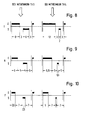
- E means the drum operation in the emptying direction of rotation and S the drum operation in the scooping direction of rotation (in FIG. 3 in each case related to the larger chamber 32).
- the intensive aisle for drivers according to FIG. 3 is divided into 8 s emptying rotation direction, 3 s standstill, 6 s scooping rotation direction and again 3 s stoppage, for drivers according to FIG. 4 in 12 s emptying rotation direction, 3 s standing still, 2 s scooping rotation direction and 3 s standstill.
- the normal gear according to FIG. 9 for drivers according to FIG. 3 shows 6 s emptying direction of rotation, 5 s standstill, 4 s scooping direction of rotation and 5 s standstill or for drivers according to FIG. 4 8.5 s emptying direction of rotation, 5 s standstill, 1.5 s scoop direction of rotation and 5 s standstill and the inlet according to FIG. 10 for drivers according to FIG. 3 3.5 s emptying direction of rotation, 7 s standstill, 2.5 s scoop direction of rotation and 7 s standstill or for drivers according to FIG. 4 5 s emptying direction of rotation, 7 s standstill, 1 s scoop direction of rotation and 7 s standstill.
- the symmetrical distribution of downtimes after each run can also be abandoned. For example, it may be advantageous if the downtimes after each run in the scoop direction of rotation are longer than after the emptying direction of rotation, so that the lye has a longer opportunity to dribble through the laundry.
- the rinsing section is also held with a reversed drum operation, which is set so that, similar to FIG. 7, the level in the tub rises and falls counter-cyclically to the amount of tubing in the laundry.
- the proportion of the drum drive in the scoop rotation direction can be larger than in the discharge rotation direction.
- the proportions of the respective drum directions of rotation will be measured. As a result, the rinse water flow through the laundry is intensified and the lye residues are better rinsed out. Otherwise, the findings from the clear wash section described above can be taken into account.
Landscapes
- Engineering & Computer Science (AREA)
- Textile Engineering (AREA)
- Control Of Washing Machine And Dryer (AREA)
- Treatment Of Fiber Materials (AREA)
- Detail Structures Of Washing Machines And Dryers (AREA)
Applications Claiming Priority (3)
| Application Number | Priority Date | Filing Date | Title |
|---|---|---|---|
| DE19873741177 DE3741177A1 (de) | 1987-12-04 | 1987-12-04 | Verfahren zum betreiben einer trommelwaschmaschine und trommelwaschmaschine zur durchfuehrung des verfahrens |
| DE3741177 | 1987-12-04 | ||
| EP88119095A EP0318761B1 (fr) | 1987-12-04 | 1988-11-17 | Procédé de fonctionnement d'une machine à laver à tambour et machine prévue à cet effet |
Related Parent Applications (1)
| Application Number | Title | Priority Date | Filing Date |
|---|---|---|---|
| EP88119095.3 Division | 1988-11-17 |
Publications (2)
| Publication Number | Publication Date |
|---|---|
| EP0475462A1 true EP0475462A1 (fr) | 1992-03-18 |
| EP0475462B1 EP0475462B1 (fr) | 1995-05-10 |
Family
ID=6341907
Family Applications (2)
| Application Number | Title | Priority Date | Filing Date |
|---|---|---|---|
| EP88119095A Expired - Lifetime EP0318761B1 (fr) | 1987-12-04 | 1988-11-17 | Procédé de fonctionnement d'une machine à laver à tambour et machine prévue à cet effet |
| EP91118837A Expired - Lifetime EP0475462B1 (fr) | 1987-12-04 | 1988-11-17 | Procédé de fonctionnement d'une machine à laver à tambour et machine prévue à cet effet |
Family Applications Before (1)
| Application Number | Title | Priority Date | Filing Date |
|---|---|---|---|
| EP88119095A Expired - Lifetime EP0318761B1 (fr) | 1987-12-04 | 1988-11-17 | Procédé de fonctionnement d'une machine à laver à tambour et machine prévue à cet effet |
Country Status (3)
| Country | Link |
|---|---|
| EP (2) | EP0318761B1 (fr) |
| DE (3) | DE3741177A1 (fr) |
| ES (2) | ES2032934T3 (fr) |
Cited By (6)
| Publication number | Priority date | Publication date | Assignee | Title |
|---|---|---|---|---|
| US5560061A (en) * | 1993-03-31 | 1996-10-01 | Bosch-Siemens Hausgeraete Gmbh | Washing machine with a reversing-mode washing drum |
| DE102005003696A1 (de) * | 2005-01-26 | 2006-07-27 | BSH Bosch und Siemens Hausgeräte GmbH | Programmgesteuerte Waschmaschine |
| WO2006108722A1 (fr) * | 2005-04-11 | 2006-10-19 | BSH Bosch und Siemens Hausgeräte GmbH | Procede de lavage de textiles retrecissants et lave-linge destine a la mise en oeuvre de ce procede |
| WO2008003594A1 (fr) * | 2006-07-06 | 2008-01-10 | BSH Bosch und Siemens Hausgeräte GmbH | Machine à laver comprenant des éléments d'entraînement creux |
| KR100802256B1 (ko) | 2001-07-26 | 2008-02-11 | 베에스하 보쉬 운트 지멘스 하우스게랫테 게엠베하 | 프로그램가능한 세탁기를 구동하기 위한 방법 및 세탁기 |
| CN104088116A (zh) * | 2014-06-24 | 2014-10-08 | 上海百强洗涤设备制造有限公司 | 一种隧道式洗涤龙的新型内滚筒结构 |
Families Citing this family (7)
| Publication number | Priority date | Publication date | Assignee | Title |
|---|---|---|---|---|
| DE4205691A1 (de) * | 1992-02-25 | 1993-08-26 | Waschgeraete Gmbh | Trommel fuer eine waschmaschine |
| KR100195453B1 (ko) * | 1996-05-11 | 1999-06-15 | 윤종용 | 드럼세탁기의 리프터장치 |
| DE10054947A1 (de) * | 2000-11-06 | 2002-05-08 | Bsh Bosch Siemens Hausgeraete | Verfahren und Vorrichtung zum Behandeln von Wäsche |
| DE10234473A1 (de) | 2002-07-29 | 2004-02-12 | BSH Bosch und Siemens Hausgeräte GmbH | Verfahren zum beschleunigten Benetzen von Wäsche in einer Trommelwaschmaschine |
| DE10326551A1 (de) | 2003-06-12 | 2005-01-05 | BSH Bosch und Siemens Hausgeräte GmbH | Wasch- und Spülverfahren für eine Waschmaschine |
| DE102006031354A1 (de) * | 2006-07-06 | 2008-01-17 | BSH Bosch und Siemens Hausgeräte GmbH | Verfahren zum Betreiben einer Waschmaschine und hierfür geeignete Waschmaschine |
| DE102009002782B4 (de) * | 2009-05-04 | 2012-02-23 | BSH Bosch und Siemens Hausgeräte GmbH | Verfahren zum Spülen in einer Waschmaschine mit einem Spülschritt bei hoher Trommeldrehzahl |
Citations (4)
| Publication number | Priority date | Publication date | Assignee | Title |
|---|---|---|---|---|
| FR1299679A (fr) * | 1961-06-15 | 1962-07-27 | Dispositif pour la circulation des bains dans les appareils de lavage, de blanchiment, de rinçage et autres appareils analogues | |
| DE1610132A1 (de) * | 1967-04-07 | 1971-04-08 | Siemens Elektrogeraete Gmbh | Verfahren zum Betreiben einer automatisch gesteuerten Trommelwaschmaschine |
| FR2548699A1 (fr) * | 1983-07-07 | 1985-01-11 | Miele & Cie | Procede de lavage pour une machine a laver a tambour a commande par programme |
| EP0245721A1 (fr) * | 1986-05-06 | 1987-11-19 | Bosch-Siemens HausgerÀ¤te GmbH | Tambour de machine à laver avec dispositif d'arrosage du linge |
-
1987
- 1987-12-04 DE DE19873741177 patent/DE3741177A1/de not_active Withdrawn
-
1988
- 1988-11-17 DE DE8888119095T patent/DE3872676D1/de not_active Expired - Lifetime
- 1988-11-17 DE DE3853786T patent/DE3853786D1/de not_active Expired - Lifetime
- 1988-11-17 ES ES198888119095T patent/ES2032934T3/es not_active Expired - Lifetime
- 1988-11-17 EP EP88119095A patent/EP0318761B1/fr not_active Expired - Lifetime
- 1988-11-17 ES ES91118837T patent/ES2073094T3/es not_active Expired - Lifetime
- 1988-11-17 EP EP91118837A patent/EP0475462B1/fr not_active Expired - Lifetime
Patent Citations (4)
| Publication number | Priority date | Publication date | Assignee | Title |
|---|---|---|---|---|
| FR1299679A (fr) * | 1961-06-15 | 1962-07-27 | Dispositif pour la circulation des bains dans les appareils de lavage, de blanchiment, de rinçage et autres appareils analogues | |
| DE1610132A1 (de) * | 1967-04-07 | 1971-04-08 | Siemens Elektrogeraete Gmbh | Verfahren zum Betreiben einer automatisch gesteuerten Trommelwaschmaschine |
| FR2548699A1 (fr) * | 1983-07-07 | 1985-01-11 | Miele & Cie | Procede de lavage pour une machine a laver a tambour a commande par programme |
| EP0245721A1 (fr) * | 1986-05-06 | 1987-11-19 | Bosch-Siemens HausgerÀ¤te GmbH | Tambour de machine à laver avec dispositif d'arrosage du linge |
Cited By (9)
| Publication number | Priority date | Publication date | Assignee | Title |
|---|---|---|---|---|
| US5560061A (en) * | 1993-03-31 | 1996-10-01 | Bosch-Siemens Hausgeraete Gmbh | Washing machine with a reversing-mode washing drum |
| KR100802256B1 (ko) | 2001-07-26 | 2008-02-11 | 베에스하 보쉬 운트 지멘스 하우스게랫테 게엠베하 | 프로그램가능한 세탁기를 구동하기 위한 방법 및 세탁기 |
| DE102005003696A1 (de) * | 2005-01-26 | 2006-07-27 | BSH Bosch und Siemens Hausgeräte GmbH | Programmgesteuerte Waschmaschine |
| WO2006079428A1 (fr) | 2005-01-26 | 2006-08-03 | BSH Bosch und Siemens Hausgeräte GmbH | Lave-linge a commande par programme |
| CN101103152B (zh) * | 2005-01-26 | 2012-05-09 | Bsh博世和西门子家用器具有限公司 | 程控洗衣机 |
| WO2006108722A1 (fr) * | 2005-04-11 | 2006-10-19 | BSH Bosch und Siemens Hausgeräte GmbH | Procede de lavage de textiles retrecissants et lave-linge destine a la mise en oeuvre de ce procede |
| EA011757B1 (ru) * | 2005-04-11 | 2009-06-30 | Бсх Бош Унд Сименс Хаусгерете Гмбх | Способ стирки подверженного усадке текстиля и стиральная машина для осуществления этого способа |
| WO2008003594A1 (fr) * | 2006-07-06 | 2008-01-10 | BSH Bosch und Siemens Hausgeräte GmbH | Machine à laver comprenant des éléments d'entraînement creux |
| CN104088116A (zh) * | 2014-06-24 | 2014-10-08 | 上海百强洗涤设备制造有限公司 | 一种隧道式洗涤龙的新型内滚筒结构 |
Also Published As
| Publication number | Publication date |
|---|---|
| EP0318761A1 (fr) | 1989-06-07 |
| EP0475462B1 (fr) | 1995-05-10 |
| DE3741177A1 (de) | 1989-06-15 |
| EP0318761B1 (fr) | 1992-07-08 |
| ES2073094T3 (es) | 1995-08-01 |
| ES2032934T3 (es) | 1993-03-01 |
| DE3853786D1 (de) | 1995-06-14 |
| DE3872676D1 (de) | 1992-08-13 |
Similar Documents
| Publication | Publication Date | Title |
|---|---|---|
| EP2044253B1 (fr) | Machine à laver comprenant des éléments d'entraînement creux | |
| EP0245721B1 (fr) | Tambour de machine à laver avec dispositif d'arrosage du linge | |
| DE68928640T2 (de) | Trommelwaschmaschine | |
| DE69508989T2 (de) | Verfahren zum Waschen in einer Waschmaschine mit senkrechter Achse | |
| EP0475462B1 (fr) | Procédé de fonctionnement d'une machine à laver à tambour et machine prévue à cet effet | |
| DE736334C (de) | Waschmaschine zum Waschen und Trockenschleudern von Waeschestuecken | |
| EP0043122B1 (fr) | Procédé pour le lavage du linge et machine à laver à tambour destinée à l'exécution du procédé | |
| EP2049723B1 (fr) | Détermination de la capacité d'accumulation d'eau de textiles dans un lave-linge et lave-linge correspondant | |
| DE20023048U1 (de) | Von vorn beschickbare Waschmaschine mit einer drehbaren Wäschetrommel | |
| DE4104450A1 (de) | Verfahren und einrichtung zum waschen von textilien in einem waschvollautomaten nach dem doppeltrommelprinzip und recyclingbehaelter zum speichern von flotten | |
| DE69313974T2 (de) | Waschmaschine mit dynamischem Fluss | |
| DE4326496C2 (de) | Trommelwaschmaschine mit einer drehbar gelagerten Wäschetrommel | |
| DE112017000598B4 (de) | Trommelwaschmaschine und verfahren zum reinigen einer wanne derselben | |
| CH645144A5 (de) | Verfahren und vorrichtung zum waschen von waesche. | |
| DE10136519B4 (de) | Verfahren zum Betreiben einer programmierbaren Waschmaschine und dafür geeignete Waschmaschine | |
| DE2226992C3 (de) | Gegenstromwaschverfahren in einer aus mehreren Wascheinheiten bestehenden Waschmaschine | |
| EP1846607B1 (fr) | Procede pour nettoyer et impregner des textiles | |
| DE69703779T2 (de) | Waschmaschine mit senkrechter Achse und mit rotierender Waschplatte | |
| DE3820409C2 (fr) | ||
| DE69907902T2 (de) | Waschmaschine | |
| DE4331632C2 (de) | Verfahren zum Spülen und Schleudern von Wäsche in einer programmgesteuerten Waschmaschine | |
| DE4205691A1 (de) | Trommel fuer eine waschmaschine | |
| EP0304391A1 (fr) | Machine à laver à tambour | |
| DE19824403A1 (de) | Verfahren zum Wassereinfüllen bei einer programmgesteuerten Waschmaschine | |
| DE102015101456A1 (de) | Trommel für eine Waschmaschine und Waschmaschine |
Legal Events
| Date | Code | Title | Description |
|---|---|---|---|
| PUAI | Public reference made under article 153(3) epc to a published international application that has entered the european phase |
Free format text: ORIGINAL CODE: 0009012 |
|
| AC | Divisional application: reference to earlier application |
Ref document number: 318761 Country of ref document: EP |
|
| AK | Designated contracting states |
Kind code of ref document: A1 Designated state(s): DE ES FR IT |
|
| 17P | Request for examination filed |
Effective date: 19920825 |
|
| RAP3 | Party data changed (applicant data changed or rights of an application transferred) |
Owner name: BOSCH-SIEMENS HAUSGERAETE GMBH |
|
| 17Q | First examination report despatched |
Effective date: 19940328 |
|
| GRAA | (expected) grant |
Free format text: ORIGINAL CODE: 0009210 |
|
| AC | Divisional application: reference to earlier application |
Ref document number: 318761 Country of ref document: EP |
|
| AK | Designated contracting states |
Kind code of ref document: B1 Designated state(s): DE ES FR IT |
|
| REF | Corresponds to: |
Ref document number: 3853786 Country of ref document: DE Date of ref document: 19950614 |
|
| ITF | It: translation for a ep patent filed | ||
| ET | Fr: translation filed | ||
| REG | Reference to a national code |
Ref country code: ES Ref legal event code: FG2A Ref document number: 2073094 Country of ref document: ES Kind code of ref document: T3 |
|
| PLBE | No opposition filed within time limit |
Free format text: ORIGINAL CODE: 0009261 |
|
| STAA | Information on the status of an ep patent application or granted ep patent |
Free format text: STATUS: NO OPPOSITION FILED WITHIN TIME LIMIT |
|
| 26N | No opposition filed | ||
| PGFP | Annual fee paid to national office [announced via postgrant information from national office to epo] |
Ref country code: ES Payment date: 20021127 Year of fee payment: 15 |
|
| PG25 | Lapsed in a contracting state [announced via postgrant information from national office to epo] |
Ref country code: ES Free format text: LAPSE BECAUSE OF NON-PAYMENT OF DUE FEES Effective date: 20031118 |
|
| REG | Reference to a national code |
Ref country code: ES Ref legal event code: FD2A Effective date: 20031118 |
|
| PGFP | Annual fee paid to national office [announced via postgrant information from national office to epo] |
Ref country code: DE Payment date: 20071130 Year of fee payment: 20 |
|
| PGFP | Annual fee paid to national office [announced via postgrant information from national office to epo] |
Ref country code: IT Payment date: 20071127 Year of fee payment: 20 |
|
| PGFP | Annual fee paid to national office [announced via postgrant information from national office to epo] |
Ref country code: FR Payment date: 20071120 Year of fee payment: 20 |