EP0475469A2 - Vorrichtung zum automatischen Umformen von metallischen Bändern in Träger durch longitudinales transversales Biegen, Stanzen und Ziehen nach elektronisch programmierbaren Profilen - Google Patents
Vorrichtung zum automatischen Umformen von metallischen Bändern in Träger durch longitudinales transversales Biegen, Stanzen und Ziehen nach elektronisch programmierbaren Profilen Download PDFInfo
- Publication number
- EP0475469A2 EP0475469A2 EP91201231A EP91201231A EP0475469A2 EP 0475469 A2 EP0475469 A2 EP 0475469A2 EP 91201231 A EP91201231 A EP 91201231A EP 91201231 A EP91201231 A EP 91201231A EP 0475469 A2 EP0475469 A2 EP 0475469A2
- Authority
- EP
- European Patent Office
- Prior art keywords
- prisms
- clamp
- rotation
- sheet metal
- manipulator
- Prior art date
- Legal status (The legal status is an assumption and is not a legal conclusion. Google has not performed a legal analysis and makes no representation as to the accuracy of the status listed.)
- Withdrawn
Links
- 239000002184 metal Substances 0.000 title claims abstract description 47
- 230000001131 transforming effect Effects 0.000 title claims description 3
- 238000005452 bending Methods 0.000 claims abstract description 31
- 230000033001 locomotion Effects 0.000 claims abstract description 17
- 238000000034 method Methods 0.000 claims abstract description 16
- 230000008569 process Effects 0.000 claims abstract description 7
- 239000006096 absorbing agent Substances 0.000 claims description 19
- 230000035939 shock Effects 0.000 claims description 18
- 241000239290 Araneae Species 0.000 claims description 11
- 238000006073 displacement reaction Methods 0.000 claims description 7
- 210000003414 extremity Anatomy 0.000 description 15
- 210000000056 organ Anatomy 0.000 description 15
- 238000013519 translation Methods 0.000 description 15
- 230000014616 translation Effects 0.000 description 15
- 230000009471 action Effects 0.000 description 8
- 210000003141 lower extremity Anatomy 0.000 description 8
- 210000001364 upper extremity Anatomy 0.000 description 6
- 238000004080 punching Methods 0.000 description 5
- 238000004519 manufacturing process Methods 0.000 description 4
- 230000007246 mechanism Effects 0.000 description 4
- 230000008878 coupling Effects 0.000 description 3
- 238000010168 coupling process Methods 0.000 description 3
- 238000005859 coupling reaction Methods 0.000 description 3
- 230000010355 oscillation Effects 0.000 description 3
- 230000001154 acute effect Effects 0.000 description 2
- 238000007599 discharging Methods 0.000 description 2
- 230000000694 effects Effects 0.000 description 2
- 238000007789 sealing Methods 0.000 description 2
- 238000010008 shearing Methods 0.000 description 2
- 241000397426 Centroberyx lineatus Species 0.000 description 1
- 229910000831 Steel Inorganic materials 0.000 description 1
- 230000001133 acceleration Effects 0.000 description 1
- 230000006978 adaptation Effects 0.000 description 1
- 230000005540 biological transmission Effects 0.000 description 1
- 230000015572 biosynthetic process Effects 0.000 description 1
- 238000005266 casting Methods 0.000 description 1
- 238000010276 construction Methods 0.000 description 1
- 230000005484 gravity Effects 0.000 description 1
- 239000000463 material Substances 0.000 description 1
- 230000000149 penetrating effect Effects 0.000 description 1
- 230000009467 reduction Effects 0.000 description 1
- 238000005096 rolling process Methods 0.000 description 1
- 238000007493 shaping process Methods 0.000 description 1
- 239000010959 steel Substances 0.000 description 1
- 230000001360 synchronised effect Effects 0.000 description 1
Images


Classifications
-
- B—PERFORMING OPERATIONS; TRANSPORTING
- B21—MECHANICAL METAL-WORKING WITHOUT ESSENTIALLY REMOVING MATERIAL; PUNCHING METAL
- B21D—WORKING OR PROCESSING OF SHEET METAL OR METAL TUBES, RODS OR PROFILES WITHOUT ESSENTIALLY REMOVING MATERIAL; PUNCHING METAL
- B21D5/00—Bending sheet metal along straight lines, e.g. to form simple curves
- B21D5/04—Bending sheet metal along straight lines, e.g. to form simple curves on brakes making use of clamping means on one side of the work
- B21D5/045—With a wiping movement of the bending blade
-
- B—PERFORMING OPERATIONS; TRANSPORTING
- B21—MECHANICAL METAL-WORKING WITHOUT ESSENTIALLY REMOVING MATERIAL; PUNCHING METAL
- B21D—WORKING OR PROCESSING OF SHEET METAL OR METAL TUBES, RODS OR PROFILES WITHOUT ESSENTIALLY REMOVING MATERIAL; PUNCHING METAL
- B21D35/00—Combined processes according to or processes combined with methods covered by groups B21D1/00 - B21D31/00
Definitions
- the present invention relates to a machine suitable for automatically transforming bands of metal sheet into beams that are bent longitudinally according to electronically programmable profiles, as well as punched, drawn and bent transversally.
- the known techniques for bending strip of sheet metal, several times and in various directions so as to obtain beams of various shapes are substantially three: the shaping of continuous bands by means of the so-called roller forming machines, in which the profile is formed by the gradual adaptation of the band to the profiles of the numerous pairs of rollers in line which, rotating synchronously, move the band itself; the bending by means of so-called press brakes, in which the bends are executed one at a time on strips with a length of a few meters with the action of a rectilinear and acute blade which penetrates into the groove of a fixed counterblade obstructed by the sheet metal to be bent; the forming by means of common presses, wherein a half-die integral with the movable ram, penetrating into a half-die integral with the base, executes several bends simultaneously.
- the first technique can only be used in the manufacture of large quantities of sections having the same profiles and different lengths, because the process for designing and manufacturing the profile forming rollers and for replacing them on the machine at the start of each new production run is long and expensive; in addition, it is not possible to execute drawing operations and transversal bends on the sections during the profile forming process.
- the second technique uses a single die wherein during the bending operation no point of the sheet metal strip is stationary with respect to the base of the machine; it follows that:
- the third technique generally uses several dies simultaneously, located on the same press and a transfer device which grasps the extremities of the strips at each forming station and makes them advance by one step; this technique is highly productive, but it is rigid, because the section which can be produced and the length of the strips are only those for which the die has been manufactured.
- the main object of the present invention is to accomplish a machine which, at one and the same time, is highly productive, very flexible and can be automated completely to produce beams which are in any case punched, drawn and bent and of any length shorter than a maximum pre-set value.
- a second object of the present invention is to allow the easy handling of the strips of sheet metal being processed, using tools which leave one edge of the sheet metal immobile during the bending operation.
- a third object of the present invention is to have a large number of bending, punching and drawing dies arranged in a limited space and always ready for operations so that, with the same configuration of the machine, it is possible to produce sections having a complex form or several different profiles.
- a fourth object of the invention is to accomplish a machine which may be supplied directly with one or more bands of sheet metal wound in coils.
- a machine which may be used not only for bending bands of sheet metal longitudinally but also for punching, drawing and bending them transversally, characterised in that it comprises two prisms having a vertical axis and a polygonal cross-section with lateral faces which support respective half-dies co-operating with one another in twos to bend, draw or punch a band of sheet metal placed between them, means for causing the rotation of said prisms with respect to their vertical axes for the positioning of said half-dies in respective operating positions opposite to one another, means for causing said prisms to move reciprocally closer and further away in a vertical plane comprising said axes, and a manipulator provided with a grasping clamp suitable for vertically supporting from above a band of sheet metal and provided with the possibility of movement along a first horizontal axis passing between the above prisms and perpendicular to said vertical plane of movement of the prisms, along a second horizontal axis perpendicular to the former and along and on a vertical
- the present invention provides that on the flat faces of the two prisms having a polygonal cross-section with vertical and parallel axes there are arranged pairs of bending, drawing or punching half-dies which, interacting with one another by one drawing closer to the other, due to the rotation and then the translation of the above prisms, with a force sufficient to cause the required deformation of the sheet metal, execute the desired operations.
- the axes of the two prisms are made to move in a direction parallel to one another, causing the two half-dies applied to the two opposite faces of the prisms themselves to move closer together and to compenetrate one into the other.
- one of the two prisms can have the axis fixed with respect to the base.
- Movable horizontal carriages supporting the end pivots of the prisms are coupled for translation to a strong rectangular frame, whose middle vertical plane is parallel to the plane of the axes of the prisms and which constitutes the fixed structure of the machine.
- a manipulator In the central part of the machine's upper horizontal beam there is a manipulator with a clamp as the grasping organ.
- Said clamp moves according to three numerically controlled axes: a horizontal rectilinear axis of translation orthogonal to the plane of the frame, a horizontal axis perpendicular to the preceding one and a vertical axis of rotation.
- the clamp has the possibility of assuming two positions not far from one another in a vertical direction.
- the clamp can thus reach any point of a horizontal rectangle, whose long sides are perpendicular to the plane passing through the axes of the die-holding prisms, and at any of such points it can assume any angular orientation and execute a small vertical displacement.
- Said clamp has the jaws which open and close by rotating on a horizontal axis and is therefore suitable for grasping the strip of sheet metal being processed along a segment of a straight line which is parallel and close to a short side of the strip itself and for holding the strip in a vertical plane.
- the clamp Since the clamp on occasion must have narrow jaws so as to grasp very short rectilinear edges of the bent strip and sometimes must have wide jaws so as to grasp wider edges, and this so as to be able to move the strip under all circumstances with the maximum acceleration, the clamp is automatically interchangeable with other clamps deposited in a magazine forming part of the same machine.
- the clamp With its motion the clamp can go to withdraw a strip issuing vertically from a shearing unit mounted in front of the frame or from a sheaf of strips arranged in a container, to arrange the strip in a well-defined position between two half-dies applied to the prisms for each of the operations of deformation of the strip and, at the end of the process, move the finished beam to a vertical container arranged on the opposite side of the frame.
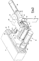
- Fig.s 1 and 2 give a schematic representation of the general architecture of the machine.
- a supporting structure 1 which, independently of the material with which it is accomplished (steel casting, welded sheet metal, etc.) and of the particular sub-division into smaller parts suitable for making it easier to produce and/or to transport, has the form of a closed portal with a base 2, cross-beam 3 and uprights 4, with projections 5 and 6 on the right hand side, 7 on the front and 8 on the rear, which support some of the machine's active organs.
- Both prisms 8 and 9 are suitable for supporting on their faces respective half-dies for processing (bending, drawing, punching) a sheet metal.
- control organs 15 and 16 for the translation of the right hand prism 10.
- a manipulator 18 which supports and moves the strip of sheet metal 40 being processed.
- an automatic clamp magazine 19 is applied.
- the manipulator 18 slides on beam 17 along precision guides 20 and 21, operated by a motor 22 which, through a possible reduction unit 134, rotates a toothed pinion, not visible in the figure, which engages a rack 23.
- a motor 22 which, through a possible reduction unit 134, rotates a toothed pinion, not visible in the figure, which engages a rack 23.
- shock absorbers 24 and 25 Fig. 2
- the manipulator 18 has a carriage 26, slidable along the beam 17, which supports an overhanging beam 27, along which, on precision guides 29 and 30, there moves another carriage 28 operated by a motor 31, which acts through pulleys 32 and 33, a toothed belt 34 and a screw 35.
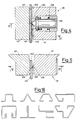
- a clamp 36 On carriage 28 there is hinged a clamp 36, which is made to rotate on a vertical axis 37 by a motor 38, which transmits motion to it by means of a worm screw and a helical pinion of which Fig. 3 shows the casing 39.
- the clamp 36 is provided with two jaws 41 and 42, which are held open by springs and closed by a hydraulic cylinder not visible in the figure.
- the clamp 36 is also moved vertically by a hydraulic cylinder (not shown) between two fixed positions very close to one another.
- the clamp 36 is fastened to a support shaft rotating on axis 37 so that it can be automatically removed and changed with a clamp having a different size, contained in the magazine 19 (Fig. 2).
- one of the clamps 36 furnished with the machine contains inside a jaw 41 provided with a grasping pawl 139 and with a clamping edge or lip 137 a cylindrical/conical pin 135 provided with a tip 136 which protrudes by a few tenths of a millimeter from the clamping lip 137 of the jaw 41, said pin being held in position by a very rigid spring 138; when said clamp is completely closed against the strip of metal sheet 40, the tip 136 of the pin 135 and the grasping pawl 139 of the jaw 41 are embedded in the sheet metal 40 and the spring 138 is compressed more than when the clamp is open; following a small movement of the jaws 41, 42 away from each other the clamping lip 137 is no longer in contact with the sheet metal 40, while the tip 136 of pin 135 is still embedded in the sheet metal 40 under the action of the spring 138.
- the strip of sheet metal 40 can rotate on the axis of the pin 135, sliding against a flat surface 140 of the jaw 42.
- This allows the execution on the strip of sheet metal 40 of bends which are not parallel to one other, by making an angle between the strip and the half-dies, which are vertical, of which further details shall be given later.
- the inclination always of a few degrees, is obtained by a small displacement of the carriage 26 along the beam 17, while the clamp 36 is arranged with its clamping lip 137 parallel to the beam 17 and while the lower extremity of the strip of sheet metal 40 is prevented from moving by a protrusion of the half-dies.
- Each spare clamp is inserted in the spider 160 by the sliding of the lateral edges of the seats 159 in grooves 161 and 162 obtained in the sides of each clamp.
- each clamp 36 from its seat 159 is hindered by a spring-operated dog 163.
- the spider 160 which is flat and arranged in a horizontal plane, can rotate on a vertical axis 200 passing through its centre and can stop accurately in the positions opposite which a seat for a clamp is in the position of Fig. 7, which is that wherein there occurs the passage of the clamp from the manipulator 18 to the spider 160 and vice versa.
- the fastening of the clamp 36 to a terminal part 164 of the manipulator 18 is obtained by a swallow-tail coupling, whose clearance is eliminated and the sliding prevented by a wedge 165 pushed to wedge itself by a spring 166.
- the closing organs of the clamp 36 that is, a hydraulic cylinder 167 and its accessories, which act on the hinged jaw 41 are incorporated in the terminal part 164 of the manipulator 18.
- a small pneumatic or hydraulic cylinder 168 integral with a supporting structure 169 (Fig. 2) of the spider 160 is in line with the wedge 165 and can push it up against the spring 166 to release the clamp 36 from the terminal part 164 of the manipulator 18.
- the left hand prism 9 is rotatably constrained with its lower extremity to the base 2 and with its upper extremity to the beam 3.
- the lower extremity extends downward with a shaft 43 which terminates with a gear 44 engaging a pinion 45 operated by a motor 46.
- Two toothed polygonal plates 47 and 48 with teeth 65 are integral with the lower extremity and with the upper extremity, respectively, of the left hand prism 9.
- Fig. 9 which simultaneously represents the two distinct but substantially identical cross-sections IX-IX of Fig. 8, the lower seen from above and the upper seen from below, both toothed polygonal plates 47 and 48 are seen. Between the toothed plate 47 and the base 2 and between the toothed plate 48 and the beam 3 there are two levers 49 and 50, identical one with the other. Each of these two levers, remaining in its horizontal plane because held there by sliding surfaces belonging to the adjacent casings, can slide with respect to a small parallelepiped block 51 (Fig. 9) in turn rotating on a pivot 52 integral with the base 2 and with the beam 3, respectively.
- the sliding action of the levers 49 and 50 on the small blocks 51 is operated by small hydraulic cylinders 53 and 54, having the casing hinged on supports 55 and 56, integral with the base 2 and with the beam 3, respectively, and having the stem hinged with respective extremities of the lever 49 and of the lever 50.
- Opposite extremities 57 and 58 of the levers 49 and 50 move between a pair of hydraulic shock absorbers 59 and 62 and a pair of hydraulic shock absorbers 60 and 61, respectively, whose casings are integral with the structure 1 and whose stems are, on the other hand, movable and suitable for absorbing the kinetic energy transmitted to them by the extremities 57, 58 of the levers 49, 50.
- the levers 49, 50 When the small cylinders 53, 54 are expanded, the levers 49, 50 have respective teeth 63, 64 outside the space traversed by the teeth 65 of the toothed plates 47, 48 and thus, under these conditions, the left hand prism 9 can rotate freely on its axis moved by motor 46. But if the small cylinders 53, 54 are contracted, as in Fig. 5, the teeth 63, 64 interefere with the teeth 65 and stop the rotation of the toothed plates 47, 48 and of the left hand prism 9, with which they are integral, discharging the kinetic energy on the pair of hydraulic shock absorbers 59, 60 or 61, 62. Pairs of hydraulic cylinders 66, 67 and 68, 69 set the lever 49 and the lever 50, respectively, against the shock absorbers opposite those which shall execute the next braking of the rotation of the prism 9.
- the right hand prism 10, as opposed to the left hand prism 9, is not rotatably constrained directly to the base 2 and to the beam 3, but with its lower extremity to a carriage 71 and with its upper extremity to a carriage 72.
- the carriage 71 can only translate horizontally on the base 2 towards the prism 9 under the action of the driving organ 15 (Fig. 1), being guided by precision guides 73, 74, 75.
- the carriage 72 is constrained to the beam 3 only by a precision guide 76 so that, under the action of the driving organ 16 (Fig.
- the right hand prism 10 is also made to rotate on its axis by a motor 80, whose shaft carries a toothed pinion 81 which engages with a wheel 82 integral with a pivot 83, extension of the prism 10.
- a casing 84 which encloses the pair of gears 81, 82 and which supports the motor 80, remains always coaxial with the pivot 83, as it is spherically coupled with the lower face of the carriage 71 and being constrained to the base 2 only to the extent of not being allowed to rotate.
- Fig. 11 which simultaneously represents the two distinct but substantially identical sectional views XI-XI of Fig. 10, the lower seen from above and the upper seen from below, both toothed polygonal plates 85 and 86 are seen.
- the sliding action of the levers 87 and 88 on the small blocks 89 is operated by small hydraulic cylinders 91 and 92, having the casing hinged on supports 93 and 94, integral with the carriage 71 and with the carriage 72, respectively, and having the stem hinged with respective extremities of the lever 87 and of the lever 88.
- Opposite extremities 95, 96 of the levers 87, 88 move between a pair of hydraulic shock absorbers 97, 99 and a pair of hydraulic shock absorbers 98, 100, respectively, whose casings can be adjusted with respect to the structure 1 and whose stems are suitable for absorbing the kinetic energy transmitted to them by the extremities 95, 96 of the levers 87, 88.
- the levers 87, 88 When the small cylinders 91, 92 are expanded, the levers 87, 88 have respective teeth 101, 102 outside the space traversed by the teeth 103 of the toothed plates 85, 86, but not outside the space traversed by the tooth 104 of each toothed plate, which protrudes more than the others. It follows that, under these conditions, the right hand prism 10 can perform almost one revolution but no more. This is to avoid breaking the electrical cables, which enter the right hand prism 10 along the shaft 83, which is hollow, as a result of an undefined rotation in the same direction.
- the teeth 101, 102 also interfere with the teeth 103 and stop the rotation of the toothed plates 85, 86 and of the right hand prism 10, discharging their kinetic energy on the pair of hydraulic shock absorbers 97, 99 or 98, 100.
- the pairs of hydraulic cylinders 105, 106 and 107, 108 set the lever 87 and the lever 88, respectively, against the shock absorbers opposite those which shall execute the next braking of the rotation of the prism 10.
- the left hand prism 9 rotates to move quickly to one of the positions, which in the figures are, for example, nine, wherein one of the half-dies applied to the faces of the prism is exactly in the operating position, facing the corresponding half-die carried by the prism 8.
- the prism 10 also rotates with an identical mechanism to take the correct die to the operating position, but this can rotate, through a small angle, even during the bending operation, to execute possible bends with an angle greater than 90 degrees.
- the amount of the operating rotation is a function of the thickness of the metal sheet, of the quality of the metal sheet, of the bending angle and of the shape of the die and it must be set with great accuracy. In addition this rotation requires a large force, because it is necessary to overcome the resistance of the metal sheet to be bent.
- Fig. 12 which is a sectional view taken along the line XII-XII of Fig. 11, illustrates the mechanism with which the small operational rotation of the right hand prism 10 is attained with a large force and great precision.
- the same mechanism is installed both at the lower extremity and at the upper extremity of the right hand prism 10, but Fig. 12 illustrates only that installed at the lower extremity.
- Two motors 109 and 110 rotate two small shafts 111 and 112, with each of which two toothed pinions 113, 114 and 115, 116 are integral.
- Each of said pinions engages with an externally toothed and internally threaded ring 117, 118, 119, 120, which is screwed onto the cylindrical casing 97, 99 of one of the shock absorbers, which is prevented from rotating by a small key 125, 126.
- the extremity of the casing of each shock absorber opposite to that from which the stem protrudes, terminates with a piston 121, 122, which penetrates into the chamber of simple-action hydraulic cylinder 123, 124.
- the extremities of the stroke of each of said pistons 121, 122 are determined by the positions at which the corresponding rings 117, 119 or 118, 120 are set by the motors 109, 110. In this way the small operational rotations of the prism 10 are executed by hydraulic cylinders 123, 124 but set in their amplitude by rotative motors 109, 110.
- Fig. 13 which represents the organs 15 operating the translation of the lower carriage 71 of the right hand prism 10, installed on the projection 5 of the base 2 (Fig. 1) which are repeated exactly (16) on the projection 6 for the carriage 72
- the translation of the carriages is operated in the direction of operations by two pairs of single-action hydraulic cylinders 127, 128 and 129, 130 which push only against the carriages, through spherical and flat surfaces, which allow misalignments and inclinations.
- the motion of said cylinders is operated by electro-hydraulic servovalves.
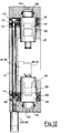
- Fig 14 there is shown a horizontal sectional view of a typical bending die and of a hydraulic metal sheet holder associated with the right hand prism 10.
- the die is divided into two half-dies 143 and 144, the first applied to a face 145 of the left hand prism 9 and the second to a face 146 of the right hand prism 10.
- the two half-dies 143 and 144 are represented in the position at the start of the bending operation, that is, with the faces 145 and 146 of the left hand prism 9 and of the right hand prism 10, respectively, parallel to one another, both prisms are held by their respective motors 46 (Fig. 8) and 80 (Fig.
- the half-die 144 also comprises a blade 151.
- the metal sheet holder 148 and the blade 151 are mounted on a die holder 152 and this is in turn held by means of quick-action holding means 153 on the right hand prism 10.
- a series of hydraulic cylinders 154 incorporated in the right hand prism 10 oppose a force adjusted with known devices to the sliding action of the sheet metal holder 148 in the die holder 152.
- the counterblade 150 is mounted in a die holder 155 and this in turn is held by means of quick-action holding means 156 on the right hand prism 9.
- an unwinding reel 190 with two coaxial and opposite chucks 191 and 192, each of which, expanding and rotating, supports and causes to rotate a coil 193, 194 of band 196, the first shown in line with the position wherein the strip 40 arranged vertically shall be grasped at its upper extremity by the clamp 36 and the second in a position such as to be easily replaced by a third coil.
- the unwinding reel 190 is rotatable on a vertical axis 195 passing through its centre.
- the band 196 which unwinds from the coil 193, forms a downward loop, which falls even below the lower face of the base 2 (Fig. 1) and then rises vertically with its free extremity just on the vertical line of the clamp 36, taken by the manipulator 18 to the grasping position, as in Fig. 2.
- the band 196 passes through a straightening/feeding unit with rollers 197, which, in addition to removing from the band the curvature due to its having been wound on the coil, advances the front of the band along a suitable vertical guide by an amount sufficient to make it penetrate some millimeters between the jaws of the clamp 36.
- a straightening/feeding unit 197 there are three shears: one shear with horizontal blades not represented in Fig. 15, which cuts the strip transversally, removing the strip 40, and two shears with circular blades, 198 and 199, which may be moved away from one another to a greater or lesser degree according to the width required for the strip 40, which trim the edges of the band 196, before the tranversal cut.
- the twin unwinding reel 190, the straightening/feeding unit 197 and the shears 198, 199 are all within the scope of the known art and are not therefore described in detail, but only outlined to give an example of a possible solution to the problem of automatically generating the strip 40.
- the straightening and shearing unit is movable vertically and must, on each occasion, be positioned at the height corresponding to the length of the strip 40.
- the coil of band of sheet metal 193 is unwound due to the effect of the synchronised motion of the chuck 191, of the reel 190 and of the straightening/feeding unit 197, maintaining the amplitude of the loop and preparing a vertical part of band as wide and as long as the strip 40 which will have to be bent according to a given profile, described by a suitable program introduced into an electronic controller of the machine, built and instructed according to known techniques.
- the trim scrap that is, the two narrow strips removed from the edges of the original band 196 to reduce it to the required width, must be cut into small pieces by the same circular blades and allowed to fall into a container.
- the manipulator 18 moves the clamp 36 to the position at which it can grasp the top of the straightened and trimmed band and the clamp closes.
- the transversal shears separate the strip 40 from the band 196 and the manipulator, by moving along the beam 17, takes the strip to the correct position between the half-dies 143 and 144, which are moved away from one another, thanks to a suitable translation of the prism 10, enough for the strip 40 to slide in between them.
- the manipulator 18 moves the strip 40 close to the face 149 of the counterblade 150, causing the acute corner of the counterblade 150 to coincide with the straight line along which the strip is to be subjected to the first bend.
- the prism 10 translates, first moving the face 147 of the sheet metal holder 148 close to the strip 40 and then, while the cylinders 154 engaged along the length of the strip 40 keep the strip 40 tightly up against the counterblade 150, making the active edge of the blade 151 advance beyond the corner of the counterblade 150 and thus causing the strip 40 to be bent.
- the bending angle is less than 90 degrees, this is obtained with an appropriate translation of the prism 10; if, on the other hand, the angle is equal to or greater than 90 degrees, after the translation a small rotation must also be executed, anti-clockwise if seen from above, of the prism 10, obtained by means of the pushing action of the lower and upper hydraulic cylinders 123 until the rings 118 are moved against the abutment, after their adjustment on the part of the motor 109.
- the opposite rotation thanks to the motor 80 and the opposite translation thanks to the cylinders 131 and 132 release the bent strip, still held by the clamp 36, which has not moved during the bending operation.
- next bend is to be executed in the same direction as the first, the same die is used and thus the operation may be repeated in exactly the same way, after the translation of the clamp in a direction parallel to the face 149 of the counterblade 150 and after the adjustment, if any, of the ring 118, if the new bending angle is not less than 90 degrees and different from the preceding one.
- a die which is the mirror image of that illustrated in Fig. 14 must be brought automatically into the operating position and the half-dies of the mirror-image die are applied to two faces of the prism 9 and of the prism 10, adjacent to those visible in Fig. 14.
- the changeover of the two half-dies in the operating position is made by the simultaneous rotation, anti-clockwise if seen from above, of the two prisms 9 and 10 on the part of the respective motors 46 and 80, braked by the respective shock-absorbers 60, 62 and 97, 100.
- the seven faces of the prism 9 not occupied by the half-die 143 and by its mirror-image 144 can be occupied by half-dies that are similar but which have a counterblade with a different profile, compatible with profiles of the strip 40 impossible to obtain with the counterblade 150 and its mirror-image blade 151.
- the same faces of the prism 9 and the homologous faces of prism 10 can be occupied by half-dies designed for operations other than the longitudinal bending of the strips 40, such as, say, transversal bending at different levels, punching, drawing, markings, etc..
- the levers 49, 50 of the prism 9 and the levers 87, 88 of the prism 10 must be displaced radially by the small cylinders 53, 54 and 91, 92, respectively, to allow the passage of teeth 65 and 104, and then moved back to the initial position to await the arrival of the teeth to be held.
- the clamp 36 With the largest jaw width compatible with the width of the edge of the strip to be grasped and thus in the passage from one lot of strips to another and on occasion during the bending operation of any one strip the clamp must be changed.
- the spider 160 rotates so that one of the empty seats 159 is in the position which can be reached by the clamp on board the manipulator 18; the manipulator 18 causes its clamp 36 to slide into the empty seat; the small cylinder 168 pushes up against the wedge 165, releasing the clamp from the terminal part 164 of the manipulator 18; the manipulator 18 moves away from the spider 160, leaving the old clamp on it and the small cylinder 168 moves back; the spider 160 rotates on its vertical axis and moves the new clamp to the changeover position; the manipulator 18 aligns itself with the new clamp and then the small cylinder 168 goes to push up against the new wedge 165 to prepare the entry into the new clamp of the terminal part 164 of the manipulator 18; the manipulator 18 moves into the clamp; the small cylinder 168 moves back allowing the new clamp to lock itself onto the manipulator; lastly the manipulator takes the new clamp along with it, sliding it out of its seat 159 of the spider 160.
Landscapes
- Engineering & Computer Science (AREA)
- Mechanical Engineering (AREA)
- Bending Of Plates, Rods, And Pipes (AREA)
- Press Drives And Press Lines (AREA)
- Folding Of Thin Sheet-Like Materials, Special Discharging Devices, And Others (AREA)
Applications Claiming Priority (2)
| Application Number | Priority Date | Filing Date | Title |
|---|---|---|---|
| IT2142590 | 1990-09-11 | ||
| IT02142590A IT1244306B (it) | 1990-09-11 | 1990-09-11 | Macchina atta a trsformare automaticamente nastri di lamiera in travi piegate longitudinalmente con profili programmabili elettronicamente, nonche' punzonate, imbutite e piegate trasversalmente. |
Publications (2)
| Publication Number | Publication Date |
|---|---|
| EP0475469A2 true EP0475469A2 (de) | 1992-03-18 |
| EP0475469A3 EP0475469A3 (en) | 1993-03-17 |
Family
ID=11181601
Family Applications (1)
| Application Number | Title | Priority Date | Filing Date |
|---|---|---|---|
| EP19910201231 Withdrawn EP0475469A3 (en) | 1990-09-11 | 1991-05-24 | Machine suitable for automatically transforming bands of metal sheet into beams that are bent longitudinally according to electronically programmable profiles, as well as punched, drawn and bent transversally |
Country Status (3)
| Country | Link |
|---|---|
| EP (1) | EP0475469A3 (de) |
| JP (1) | JP2992844B2 (de) |
| IT (1) | IT1244306B (de) |
Families Citing this family (2)
| Publication number | Priority date | Publication date | Assignee | Title |
|---|---|---|---|---|
| CN106825137A (zh) * | 2015-12-04 | 2017-06-13 | 重庆银聪科技有限公司 | 一种折弯装置 |
| CN112909803B (zh) * | 2021-01-23 | 2023-01-10 | 深圳市深电高科电气有限公司 | 一种高低压成套电气柜钣金加工工艺 |
Family Cites Families (3)
| Publication number | Priority date | Publication date | Assignee | Title |
|---|---|---|---|---|
| FR2131081A5 (de) * | 1971-03-31 | 1972-11-10 | Offenstadt Georges | |
| FR2523483B1 (fr) * | 1982-03-19 | 1985-09-27 | Pauzin Alexis | Outil de pliage a plat |
| IT1219302B (it) * | 1988-05-16 | 1990-05-03 | Prima Ind Spa | Macchina per la fabbricazione di pezzi di lamiera piegata |
-
1990
- 1990-09-11 IT IT02142590A patent/IT1244306B/it active IP Right Grant
-
1991
- 1991-05-24 EP EP19910201231 patent/EP0475469A3/en not_active Withdrawn
- 1991-06-14 JP JP3143348A patent/JP2992844B2/ja not_active Expired - Fee Related
Also Published As
| Publication number | Publication date |
|---|---|
| IT1244306B (it) | 1994-07-08 |
| JPH05115928A (ja) | 1993-05-14 |
| JP2992844B2 (ja) | 1999-12-20 |
| IT9021425A0 (it) | 1990-09-11 |
| EP0475469A3 (en) | 1993-03-17 |
| IT9021425A1 (it) | 1992-03-11 |
Similar Documents
| Publication | Publication Date | Title |
|---|---|---|
| US4161110A (en) | Automatic control device for a bending machine | |
| US4495788A (en) | Multiple curvature bender | |
| US4843859A (en) | Pipe bender | |
| AT401896B (de) | Verfahren zum biegen eines werkstückes aus blech sowie blechbiegemaschine | |
| CA1336569C (en) | Plate bending machine | |
| US3581535A (en) | Method and apparatus for making blades | |
| CN108787897A (zh) | 一种一体式弯折打孔模具 | |
| US3880020A (en) | Making blades for tire curing molds | |
| US6021658A (en) | Sheet fabrication machine, and method therefor, for optimally fabricating worksheets | |
| US3902389A (en) | Turret punch press with work feed | |
| US3518908A (en) | Punch press | |
| EP0596577B1 (de) | Anlage zum Herstellen von Produkten aus drahtförmigem Material | |
| EP0475469A2 (de) | Vorrichtung zum automatischen Umformen von metallischen Bändern in Träger durch longitudinales transversales Biegen, Stanzen und Ziehen nach elektronisch programmierbaren Profilen | |
| US3472055A (en) | Bending machines for bending metal bars or sections | |
| JPH0531534A (ja) | 管成形プレス装置 | |
| RU2189291C2 (ru) | Устройство для изготовления изделий с несколькими изгибами в горизонтальной плоскости и прогибом в вертикальной плоскости | |
| RU33338U1 (ru) | Устройство для изготовления изделий с несколькими изгибами в горизонтальной и прогибом в вертикальной плоскостях | |
| EP1417054B1 (de) | Stanzmaschine für ein metallblech | |
| RU2622197C1 (ru) | Устройство для изготовления изогнутых труб | |
| EP0679455B1 (de) | Zusatzbearbeitungseinrichtung, insbesondere zum teilweise Biegen und Schneiden in einer Abkantpresse | |
| US3479855A (en) | Corrugating machine | |
| US3709025A (en) | Method and apparatus for feeding high speed presses | |
| EP0063041A2 (de) | Verfahren und Vorrichtung zum stufenweisen Biegen | |
| RU206079U1 (ru) | Станок для комбинированной обработки проволоки | |
| US20250353066A1 (en) | Forming punching apparatus |
Legal Events
| Date | Code | Title | Description |
|---|---|---|---|
| PUAI | Public reference made under article 153(3) epc to a published international application that has entered the european phase |
Free format text: ORIGINAL CODE: 0009012 |
|
| AK | Designated contracting states |
Kind code of ref document: A2 Designated state(s): AT BE CH DE ES FR GB IT LI NL SE |
|
| PUAL | Search report despatched |
Free format text: ORIGINAL CODE: 0009013 |
|
| AK | Designated contracting states |
Kind code of ref document: A3 Designated state(s): AT BE CH DE ES FR GB IT LI NL SE |
|
| 17P | Request for examination filed |
Effective date: 19930723 |
|
| STAA | Information on the status of an ep patent application or granted ep patent |
Free format text: STATUS: THE APPLICATION IS DEEMED TO BE WITHDRAWN |
|
| 18D | Application deemed to be withdrawn |
Effective date: 19931201 |