EP0475488A1 - Méthode et appareil pour commander un dispositif de friction - Google Patents
Méthode et appareil pour commander un dispositif de friction Download PDFInfo
- Publication number
- EP0475488A1 EP0475488A1 EP91202121A EP91202121A EP0475488A1 EP 0475488 A1 EP0475488 A1 EP 0475488A1 EP 91202121 A EP91202121 A EP 91202121A EP 91202121 A EP91202121 A EP 91202121A EP 0475488 A1 EP0475488 A1 EP 0475488A1
- Authority
- EP
- European Patent Office
- Prior art keywords
- accumulator
- fluid
- friction device
- path
- fluid chamber
- Prior art date
- Legal status (The legal status is an assumption and is not a legal conclusion. Google has not performed a legal analysis and makes no representation as to the accuracy of the status listed.)
- Granted
Links
Images

Classifications
-
- F—MECHANICAL ENGINEERING; LIGHTING; HEATING; WEAPONS; BLASTING
- F16—ENGINEERING ELEMENTS AND UNITS; GENERAL MEASURES FOR PRODUCING AND MAINTAINING EFFECTIVE FUNCTIONING OF MACHINES OR INSTALLATIONS; THERMAL INSULATION IN GENERAL
- F16D—COUPLINGS FOR TRANSMITTING ROTATION; CLUTCHES; BRAKES
- F16D48/00—External control of clutches
- F16D48/02—Control by fluid pressure
- F16D48/04—Control by fluid pressure providing power assistance
-
- F—MECHANICAL ENGINEERING; LIGHTING; HEATING; WEAPONS; BLASTING
- F16—ENGINEERING ELEMENTS AND UNITS; GENERAL MEASURES FOR PRODUCING AND MAINTAINING EFFECTIVE FUNCTIONING OF MACHINES OR INSTALLATIONS; THERMAL INSULATION IN GENERAL
- F16D—COUPLINGS FOR TRANSMITTING ROTATION; CLUTCHES; BRAKES
- F16D25/00—Fluid-actuated clutches
- F16D25/12—Details not specific to one of the before-mentioned types
- F16D25/14—Fluid pressure control
-
- F—MECHANICAL ENGINEERING; LIGHTING; HEATING; WEAPONS; BLASTING
- F16—ENGINEERING ELEMENTS AND UNITS; GENERAL MEASURES FOR PRODUCING AND MAINTAINING EFFECTIVE FUNCTIONING OF MACHINES OR INSTALLATIONS; THERMAL INSULATION IN GENERAL
- F16D—COUPLINGS FOR TRANSMITTING ROTATION; CLUTCHES; BRAKES
- F16D48/00—External control of clutches
- F16D48/02—Control by fluid pressure
-
- F—MECHANICAL ENGINEERING; LIGHTING; HEATING; WEAPONS; BLASTING
- F16—ENGINEERING ELEMENTS AND UNITS; GENERAL MEASURES FOR PRODUCING AND MAINTAINING EFFECTIVE FUNCTIONING OF MACHINES OR INSTALLATIONS; THERMAL INSULATION IN GENERAL
- F16H—GEARING
- F16H61/00—Control functions within control units of change-speed- or reversing-gearings for conveying rotary motion ; Control of exclusively fluid gearing, friction gearing, gearings with endless flexible members or other particular types of gearing
- F16H61/04—Smoothing ratio shift
- F16H61/06—Smoothing ratio shift by controlling rate of change of fluid pressure
- F16H61/065—Smoothing ratio shift by controlling rate of change of fluid pressure using fluid control means
- F16H61/067—Smoothing ratio shift by controlling rate of change of fluid pressure using fluid control means using an accumulator
-
- F—MECHANICAL ENGINEERING; LIGHTING; HEATING; WEAPONS; BLASTING
- F16—ENGINEERING ELEMENTS AND UNITS; GENERAL MEASURES FOR PRODUCING AND MAINTAINING EFFECTIVE FUNCTIONING OF MACHINES OR INSTALLATIONS; THERMAL INSULATION IN GENERAL
- F16D—COUPLINGS FOR TRANSMITTING ROTATION; CLUTCHES; BRAKES
- F16D48/00—External control of clutches
- F16D48/02—Control by fluid pressure
- F16D2048/0203—Control by fluid pressure with an accumulator; Details thereof
-
- F—MECHANICAL ENGINEERING; LIGHTING; HEATING; WEAPONS; BLASTING
- F16—ENGINEERING ELEMENTS AND UNITS; GENERAL MEASURES FOR PRODUCING AND MAINTAINING EFFECTIVE FUNCTIONING OF MACHINES OR INSTALLATIONS; THERMAL INSULATION IN GENERAL
- F16D—COUPLINGS FOR TRANSMITTING ROTATION; CLUTCHES; BRAKES
- F16D48/00—External control of clutches
- F16D48/02—Control by fluid pressure
- F16D2048/0209—Control by fluid pressure characterised by fluid valves having control pistons, e.g. spools
-
- F—MECHANICAL ENGINEERING; LIGHTING; HEATING; WEAPONS; BLASTING
- F16—ENGINEERING ELEMENTS AND UNITS; GENERAL MEASURES FOR PRODUCING AND MAINTAINING EFFECTIVE FUNCTIONING OF MACHINES OR INSTALLATIONS; THERMAL INSULATION IN GENERAL
- F16D—COUPLINGS FOR TRANSMITTING ROTATION; CLUTCHES; BRAKES
- F16D48/00—External control of clutches
- F16D48/02—Control by fluid pressure
- F16D2048/0221—Valves for clutch control systems; Details thereof
Definitions
- This invention relates to a method and apparatus for controlling a fluid-operated piston of a friction torque transmitting device, and more particularly, to a method and apparatus which can rapidly exhaust the fluid-operated piston, and which can separate the piston exhaust fluid from the exhaust fluid of a timing device during disengagement.
- Prior art controllers seeking to separate the fluid of the timing device from the friction device use a valve member, separate from the shift valve, to control fluid flow to and from the friction device and the accumulator. With such controllers, the timing device is exhausted through a feed restriction and/or a ball check valve to the exhaust passage of the friction device. While these controllers may provide for slightly more rapid friction device exhaust, they do not permit rapid accumulator exhaust of the timing device.
- the present invention seeks to provide an improved method and apparatus for controlling a friction device.
- an aspect of the present invention provides a control mechanism for controlling a fluid-operated friction device as specified in claim 1.
- the present invention can incorporate a flow control function for a friction device and accumulator (timing device) into a shift valve, thereby eliminating a separate control valve and the accompanying cost of manufacture and complexity of assembly.
- a flow control function can selectively interconnect the accumulator, any flow restrictions and the friction device to provide for timed engagement of the friction device while permitting rapid exhaustion of the accumulator and timed exhaustion of the friction device during disengagement.
- the friction device and the accumulator are in fluid communication with a common flow restriction during engagement and the accumulator is connected for free flow exhaust during disengagement.
- the friction device is supplied through a flow restriction during engagement and is exhausted through another flow restriction during disengagement.
- an accumulator is disposed in fluid flow arrangement with a shift valve, a flow restriction and a fluid-operated piston, and further wherein, the shift valve is selectively controlled to provide serial fluid flow between the restriction and the accumulator and between the restriction and the piston during engagement to control the timing thereof and to provide a flow path from the accumulator to exhaust in bypassing relation with the restriction and the friction device during disengagement.
- the invention is not restricted for use with any particular type of fluid-operated torque transmitting device.
- a conventional positive displacement pump 10 which is driven by an engine (not shown) is connected to deliver pressurized fluid to a passage 12.
- the pressure level in the passage 12 is controlled by a conventional regulator valve 14 which bypasses excess fluid flow to a sump or reservoir 16.
- the fluid in passage 12 is delivered to a control valve assembly 18 which comprises a plurality of conventional control elements and valve members.
- the control assembly 18 is effective to control the gear ratios in a conventional automatic transmission (not shown).
- One of the valve members included in the control assembly 18 is a shift valve 20 which includes a movable valve member 22 operable to control fluid flow between a plurality of ports or passages (hereinafter referred to simply as ports) connected to the shift valve 20.
- These ports include a supply port 24, an accumulator feed port 26, an accumulator return port 28, a clutch port 30 and two exhaust ports 32 and 34 which are, in turn, connected to the reservoir 16.
- the port 28 is connected through an accumulator passage 60 to a conventional hydraulic accumulator 62.
- accumulators have an accumulator chamber 64 and a control chamber 66.
- a spring member 68 urges a floating piston 70 in a direction to decrease the size of the accumulator chamber 64.
- the clutch port 30 is connected via a passage 40, through a restriction 42 and a parallel ball check valve 44, to a passage 46 which, in turn, is connected to a selectively engageable clutch assembly 48.
- the ball check valve 44 is open when fluid is flowing towards the port 30 so as to allow the fluid to by-pass the restriction 42 during disengagement of the clutch assembly 48.
- the passage 46 also communicates with an accumulator passage 50, which in turn, is connected to the accumulator feed port 26.
- the clutch 48 is a conventional fluid-operated friction clutch incorporating a fluid-operated piston 52, an input hub 56, an output hub 58, and a plurality of interleaved friction discs 54 which are alternately splined between the hubs 56 and 58.
- the input hub 56 is connected to a transmission input shaft, and the hub 58 is connected with a planetary gear member (neither of which is shown). Of course, the arrangement could be reversed.
- the movable valve member 22 is urged by a spring 36 to the spring set position shown.
- a shift signal passage 38 is operable to supply fluid pressure to the movable member 22 against the spring 36 to a pressure set position.
- the shift signal is generated in a conventional manner by the control assembly 18 and in general will be determined by the engine torque level and vehicle speed.
- the supply port 24 and accumulator feed port 26 are both closed by the valve 20, while the accumulator return port 28 is open in a manner as to allow free flow through exhaust port 32, and the clutch port 30 is open in a manner as to allow restricted flow through exhaust port 34, such that fluid can flow through both these ports 30, 34 into the reservoir 16.
- an accumulator valve 72 is provided.
- the valve 72 receives a torque signal via a passage 74 from the control assembly 18.
- the accumulator valve 72 modulates the signal in passage 74 and delivers the modulated signal through a passage 76 to the chamber 66.
- the pressure in chamber 66 increases, the pressure level at which the piston 70 begins to move will also increase, thereby affecting the initial pressure level directed to the piston 52.
- the fluid passing through the restriction 42 is all directed to the piston 52, until the piston 70 begins to move.
- the accumulator fluid and the clutch fluid are exhausted in unison through a single flow path, such that a longer clutch disengagement time is present.
- the accumulator chamber 64 in a conventional system, may have some residual pressure which would affect the clutch engagement time. Such an event is not likely to take place with the above-described embodiment due to the free fluid flow path between the accumulator and the reservoir which is provided by the shift valve 20.
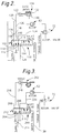
- the embodiment shown in Figure 2 includes a shift valve 100, which has associated therewith a supply port 102, an accumulator feed port 104, a clutch apply port 106, a clutch return port 108, an accumulator port 110 and a pair of exhaust ports 112 and 114.
- a shift valve 100 which has associated therewith a supply port 102, an accumulator feed port 104, a clutch apply port 106, a clutch return port 108, an accumulator port 110 and a pair of exhaust ports 112 and 114.
- the ports 102, 104 and 106 are blocked, while port 110 is connected to the reservoir at port 112, and the port 108 is connected through a restricted passage to the reservoir.
- the port 106 is connected via a passage 116 through a restriction 118 to a passage 120 which is connected to an apply piston 122 of a disc brake 124.
- the passage 120 is also in fluid communication with a passage 126 which is connected to the port 108 and a passage 128 which is connected to the port 104.
- the disc brake 124 is a conventional torque transmitting device in which a plurality of friction discs are urged into engagement by the piston 122 to establish a torque transmitting connection between a hub 130 and a housing or other stationary member 132.
- the shift valve 100 is also usable with a disc clutch, such as that described above for clutch 48.
- the port 110 is connected via a passage 134 to a conventional accumulator 62.
- the accumulator 62 has associated therewith an accumulator valve 72 which functions in a manner identical to that described for the accumulator valve in Figure 1.
- shift valve 100 When the shift valve 100 receives a shift signal through the passage 38, shift valve 100 is effective to provide fluid communication between the supply port 102 and the port 106 and also between the port 104 and the port 110. In this pressure set position, the shift valve 100 is also effective to close the ports 108, 112 and 114. With the valve 100 in the pressure set position, fluid is directed from the supply port 102 to the port 106 and through passages 116 and restriction 118 to the fluid-operated piston 122. Fluid is also directed via passages 128 and 134 to the accumulator 62.
- the restriction 118 provides a flow rate limit to the fluid entering the brake 124 and the accumulator 62, such that the restriction 118 and the fill time of the accumulator 62 are operable to provide a controlled engagement time for the brake 124.
- the initiation of engagement can be varied by the accumulator valve 72 in response to various torque signals supplied by the passage 74.
- valve 100 When the shift signal is removed from passage 38, the valve 100 will be urged to the spring set position, such that the accumulator 62 is connected directly to the reservoir and the apply piston 122 is connected via passage 126 and a restriction to the reservoir 16.
- the exhaust fluid from piston 122 bypasses the restriction 118 such that the exhaust time is substantially different from and considerably shorter than the engagement timing.
- the accumulator fluid is exhausted directly to the reservoir so that it does not affect the disengaging time of the piston 122.
- FIG. 3 A further embodiment is shown in Figure 3 in which a shift valve 200 is utilized to control the engagement and disengagement of a torque transmitting device, such as a band brake 202 as depicted, or a clutch as shown in Figure 1, or a disc brake as shown in Figure 2.
- the shift valve 200 has a supply port 204, a first outlet port 206, a second outlet port 208 and a pair of exhaust ports 210 and 212.
- the supply port 204 is connected to the supply passage from control assembly 18 through a restriction 214. In the spring set position shown, the supply port 204 is closed while the ports 206 and 208 are connected to exhaust ports 212 and 210, respectively.
- the port 206 is connected via a passage 216 with a servo piston 218 which is operable when pressurized to engage the band brake 202.
- the port 208 is connected via passage 220 with the accumulator 62.
- the accumulator 62 and its associated accumulator valve 72 function as previously described for the embodiments of Figures 1 and 2.
- the shift valve 200 upon the imposition of a shift signal in passage 38, is moved to the pressure set position, wherein the ports 210 and 212 are closed and the supply port 204 is connected with ports 206 and 208 simultaneously. Fluid pressure admitted through the port 204 is directed to both the servo piston 218 and the accumulator 62. However, as previously mentioned, all of the in-coming fluid must pass through restriction 214 which, in cooperation with the accumulator 62, provides an engagement time characteristic for the torque transmitting device 202.
- the accumulator 62 When the shift signal is removed from passage 38 and the shift valve 200 has returned to the spring set position, the accumulator 62 is connected directly with the exhaust through ports 208 and 210, while the servo piston 218 is connected to a restricted exhaust via ports 206 and 212.
- the restriction in the exhaust port for the servo piston 218 presents a minimum flow restriction to the fluid.
- the use of such exhaust restriction is not mandatory and in some instances, may not be desirable.
- the size of the exhaust passage may be sufficient to provide the desired control for exhaust flow.
- the accumulator 62 is freely exhausted during disengagement of the torque transmitting device 202. Along with being exhausted, the fluid from the accumulator 62 is separated from the flow path of the fluid leaving the servo piston 218.
Landscapes
- Engineering & Computer Science (AREA)
- General Engineering & Computer Science (AREA)
- Physics & Mathematics (AREA)
- Fluid Mechanics (AREA)
- Mechanical Engineering (AREA)
- Control Of Transmission Device (AREA)
- Hydraulic Clutches, Magnetic Clutches, Fluid Clutches, And Fluid Joints (AREA)
Applications Claiming Priority (2)
| Application Number | Priority Date | Filing Date | Title |
|---|---|---|---|
| US07/575,775 US5040653A (en) | 1990-08-31 | 1990-08-31 | Engagement and disengagement control for a friction device |
| US575775 | 1995-12-20 |
Publications (2)
| Publication Number | Publication Date |
|---|---|
| EP0475488A1 true EP0475488A1 (fr) | 1992-03-18 |
| EP0475488B1 EP0475488B1 (fr) | 1996-04-17 |
Family
ID=24301653
Family Applications (1)
| Application Number | Title | Priority Date | Filing Date |
|---|---|---|---|
| EP91202121A Expired - Lifetime EP0475488B1 (fr) | 1990-08-31 | 1991-08-20 | Méthode et appareil pour commander un dispositif de friction |
Country Status (3)
| Country | Link |
|---|---|
| US (1) | US5040653A (fr) |
| EP (1) | EP0475488B1 (fr) |
| DE (1) | DE69118788T2 (fr) |
Cited By (14)
| Publication number | Priority date | Publication date | Assignee | Title |
|---|---|---|---|---|
| EP0564363A1 (fr) * | 1992-04-03 | 1993-10-06 | Regie Nationale Des Usines Renault S.A. | Dispositif de pilotage universel de récepteur de boîte automatique |
| DE102005006431A1 (de) * | 2005-02-12 | 2006-08-24 | Volkswagen Ag | Ventilsystem bzw. Verfahren zur Steuerung einer Kupplung oder eines Gangstellers eines Kraftfahrzeuges |
| US8069661B2 (en) | 2009-02-24 | 2011-12-06 | GM Global Technology Operations LLC | Transmission hydraulic control system having an accumulator |
| US8402993B2 (en) | 2010-05-10 | 2013-03-26 | GM Global Technology Operations LLC | Hydraulic fluid cooling system for a dual clutch automatic transmission |
| US8413437B2 (en) | 2009-12-08 | 2013-04-09 | GM Global Technology Operations LLC | Transmission hydraulic control system having independently controlled stator cooling flow |
| US8434603B2 (en) | 2010-02-17 | 2013-05-07 | GM Global Technology Operations LLC | Low content control system for a dual clutch transmission |
| US8475336B2 (en) | 2009-07-30 | 2013-07-02 | GM Global Technology Operations LLC | Hydraulic control system for a dual clutch transmission |
| US8568262B2 (en) | 2009-11-13 | 2013-10-29 | GM Global Technology Operations LLC | Transmission hydraulic control system having a main line feed accumulator |
| US8613681B2 (en) | 2009-11-19 | 2013-12-24 | GM Global Technology Operations LLC | Transmission hydraulic control system having clutch compensator feed override |
| US8678780B2 (en) | 2010-02-26 | 2014-03-25 | GM Global Technology Operations LLC | Transmission hydraulic control system having a pump bypass valve |
| US8844392B2 (en) | 2010-06-09 | 2014-09-30 | Gm Global Technology Operations, Llc | Electro-hydraulic and electro-mechanical control system for a dual clutch transmission |
| US8915076B2 (en) | 2011-01-12 | 2014-12-23 | Gm Global Technology Operations, Llc | Transmission hydraulic control system having flow augmentation |
| US8942901B2 (en) | 2010-12-09 | 2015-01-27 | Gm Global Technology Operations, Llc | Method of controlling a hydraulic control system for a dual clutch transmission |
| US8967351B2 (en) | 2012-08-14 | 2015-03-03 | Gm Global Technology Operations, Llc | Transmission clutch piston compensator feed circuit |
Families Citing this family (8)
| Publication number | Priority date | Publication date | Assignee | Title |
|---|---|---|---|---|
| GB8806292D0 (en) * | 1988-03-17 | 1988-04-13 | Automotive Prod Plc | Power hydraulic system |
| US5301783A (en) * | 1992-06-24 | 1994-04-12 | General Motors Corporation | Dual pressure accumulator |
| US5389046A (en) * | 1993-05-25 | 1995-02-14 | Ford Motor Company | Automatic transmission control system |
| DE4424790A1 (de) * | 1994-07-14 | 1996-01-18 | Bosch Gmbh Robert | Hydrauliknotsteuerung für eine zwischen einem Verbrennungsmotor und einem Getriebe angeordnete Reibkupplung |
| DE19532113C2 (de) * | 1995-08-31 | 2001-06-07 | Kendrion Binder Magnete Gmbh | Druckmittelbeaufschlagte Schaltvorrichtung zum Betätigen einer druckmittelbetätigbaren Kupplung |
| GB2309494B (en) * | 1995-09-12 | 2000-04-19 | Luk Getriebe Systeme Gmbh | Motor vehicle with an apparatus for the actuation of the torque transmitting system and of the transmission |
| DE19813982C2 (de) * | 1998-03-28 | 2002-06-20 | Bosch Gmbh Robert | Kupplungssteuerung |
| DE102013108509B4 (de) * | 2012-08-14 | 2024-02-15 | GM Global Technology Operations LLC (n. d. Gesetzen des Staates Delaware) | Getriebekupplungs-Kolbenkompensator-Speisekreis |
Citations (3)
| Publication number | Priority date | Publication date | Assignee | Title |
|---|---|---|---|---|
| US2833385A (en) * | 1953-05-11 | 1958-05-06 | Gen Motors Corp | Clutch control with cooling means therefor |
| GB919616A (en) * | 1958-08-12 | 1963-02-27 | Renault | Improvements in or relating to the supply of control fluid to hydraulic clutches or brakes |
| FR2190214A5 (fr) * | 1972-06-22 | 1974-01-25 | Zahnradfabrik Friedrichshafen |
Family Cites Families (11)
| Publication number | Priority date | Publication date | Assignee | Title |
|---|---|---|---|---|
| DE933186C (de) * | 1950-08-12 | 1955-09-22 | Wilhelm Dipl-Ing Stoeckicht | Fluessigkeitsdruckbetaetigte Reibungskupplung oder -bremse |
| GB789285A (en) * | 1956-06-27 | 1958-01-15 | Gen Motors Corp | Improvements relating to power transmission mechanisms |
| US3004447A (en) * | 1956-10-16 | 1961-10-17 | Gen Motors Corp | Transmission control device |
| US3541791A (en) * | 1968-09-06 | 1970-11-24 | Kiva Yakovlevich Lvovsky | Hydraulic device for controlling the actuating cylinders of the gearshift friction clutches and brakes of self-propelled vehicles,mainly tractors |
| US3896705A (en) * | 1974-01-21 | 1975-07-29 | Clark Equipment Co | Pressure feedback system |
| SU754121A1 (ru) * | 1977-06-29 | 1980-08-07 | Всесоюзный Проектно-Технологический Институт Тяжелого Машиностроения | Гидроаккумул торный привод |
| US4560044A (en) * | 1982-06-29 | 1985-12-24 | Kabushiki Kaisha Daikin Seisakusho | Hydraulic pressure modulation device |
| JPH0788898B2 (ja) * | 1986-07-01 | 1995-09-27 | アイシン・エィ・ダブリュ株式会社 | 自動変速機における油圧サ−ボ調圧装置 |
| US4867294A (en) * | 1988-05-31 | 1989-09-19 | Tuesta Diaz De | Accumulator piston for automotive transmission |
| US4932282A (en) * | 1988-07-05 | 1990-06-12 | Ford Motor Company | Timing valve for manually selected gears of an automatic transmission |
| JPH0266369A (ja) * | 1988-08-31 | 1990-03-06 | Aisin Aw Co Ltd | 自動変速機における油圧制御装置 |
-
1990
- 1990-08-31 US US07/575,775 patent/US5040653A/en not_active Expired - Fee Related
-
1991
- 1991-08-20 EP EP91202121A patent/EP0475488B1/fr not_active Expired - Lifetime
- 1991-08-20 DE DE69118788T patent/DE69118788T2/de not_active Expired - Fee Related
Patent Citations (3)
| Publication number | Priority date | Publication date | Assignee | Title |
|---|---|---|---|---|
| US2833385A (en) * | 1953-05-11 | 1958-05-06 | Gen Motors Corp | Clutch control with cooling means therefor |
| GB919616A (en) * | 1958-08-12 | 1963-02-27 | Renault | Improvements in or relating to the supply of control fluid to hydraulic clutches or brakes |
| FR2190214A5 (fr) * | 1972-06-22 | 1974-01-25 | Zahnradfabrik Friedrichshafen |
Cited By (17)
| Publication number | Priority date | Publication date | Assignee | Title |
|---|---|---|---|---|
| FR2689595A1 (fr) * | 1992-04-03 | 1993-10-08 | Renault | Dispositif de pilotage universel de récepteur de boîte automatique. |
| EP0564363A1 (fr) * | 1992-04-03 | 1993-10-06 | Regie Nationale Des Usines Renault S.A. | Dispositif de pilotage universel de récepteur de boîte automatique |
| DE102005006431A1 (de) * | 2005-02-12 | 2006-08-24 | Volkswagen Ag | Ventilsystem bzw. Verfahren zur Steuerung einer Kupplung oder eines Gangstellers eines Kraftfahrzeuges |
| DE102005006431B4 (de) * | 2005-02-12 | 2014-10-09 | Volkswagen Ag | Ventilsystem bzw. Verfahren zur Steuerung einer Kupplung oder eines Gangstellers eines Kraftfahrzeuges |
| US8069661B2 (en) | 2009-02-24 | 2011-12-06 | GM Global Technology Operations LLC | Transmission hydraulic control system having an accumulator |
| US8475336B2 (en) | 2009-07-30 | 2013-07-02 | GM Global Technology Operations LLC | Hydraulic control system for a dual clutch transmission |
| US8568262B2 (en) | 2009-11-13 | 2013-10-29 | GM Global Technology Operations LLC | Transmission hydraulic control system having a main line feed accumulator |
| US8613681B2 (en) | 2009-11-19 | 2013-12-24 | GM Global Technology Operations LLC | Transmission hydraulic control system having clutch compensator feed override |
| US8413437B2 (en) | 2009-12-08 | 2013-04-09 | GM Global Technology Operations LLC | Transmission hydraulic control system having independently controlled stator cooling flow |
| US8434603B2 (en) | 2010-02-17 | 2013-05-07 | GM Global Technology Operations LLC | Low content control system for a dual clutch transmission |
| US8678780B2 (en) | 2010-02-26 | 2014-03-25 | GM Global Technology Operations LLC | Transmission hydraulic control system having a pump bypass valve |
| US8402993B2 (en) | 2010-05-10 | 2013-03-26 | GM Global Technology Operations LLC | Hydraulic fluid cooling system for a dual clutch automatic transmission |
| US8844392B2 (en) | 2010-06-09 | 2014-09-30 | Gm Global Technology Operations, Llc | Electro-hydraulic and electro-mechanical control system for a dual clutch transmission |
| US8942901B2 (en) | 2010-12-09 | 2015-01-27 | Gm Global Technology Operations, Llc | Method of controlling a hydraulic control system for a dual clutch transmission |
| US9765885B2 (en) | 2010-12-09 | 2017-09-19 | GM Global Technology Operations LLC | Method of controlling a hydraulic control system for a dual clutch transmission |
| US8915076B2 (en) | 2011-01-12 | 2014-12-23 | Gm Global Technology Operations, Llc | Transmission hydraulic control system having flow augmentation |
| US8967351B2 (en) | 2012-08-14 | 2015-03-03 | Gm Global Technology Operations, Llc | Transmission clutch piston compensator feed circuit |
Also Published As
| Publication number | Publication date |
|---|---|
| DE69118788T2 (de) | 1996-09-19 |
| EP0475488B1 (fr) | 1996-04-17 |
| US5040653A (en) | 1991-08-20 |
| DE69118788D1 (de) | 1996-05-23 |
Similar Documents
| Publication | Publication Date | Title |
|---|---|---|
| EP0475488B1 (fr) | Méthode et appareil pour commander un dispositif de friction | |
| US4637281A (en) | Control valve system for a four-speed automatic power transmission transaxle | |
| US4265346A (en) | Control valve mechanism for hydraulic clutch in a power transmission mechanism | |
| US4468989A (en) | Power transmission mechanism with a hydrokinetic torque converter having a lockup clutch | |
| US5908098A (en) | Regulating valve for engagement control of friction drive devices | |
| GB1576157A (en) | Transmission control system | |
| US4722251A (en) | Hydraulic circuit for controlling an automatic transmission | |
| US4665770A (en) | Control system for a multiple ratio transmission having a lockup clutch torque converter | |
| CA1168129A (fr) | Commande hydraulique pour transmission de force motrice | |
| EP0577174B1 (fr) | Appareil de transmission | |
| US3799308A (en) | Transmission clutches with feedback controlled pressure modulator | |
| US3181394A (en) | Hydraulic controls | |
| US4462280A (en) | Manual valve for hydraulic control system for automatic transmission | |
| US5957807A (en) | Transmission controller responsive to low oil temperature to delay the releasing clutch | |
| US6591958B1 (en) | Pressure control apparatus for a torque-transmitting mechanism | |
| US4966050A (en) | Control valve for reducing harshness of engagement of an automatic transmission clutch | |
| US3287995A (en) | Non-synchronous multiple speed ratio power transmission mechanism | |
| US6622835B2 (en) | Engagement control having a multiplexed hydraulic circuit for controlling a torque converter clutch and shifting clutches in an automatic transmission | |
| EP0641960B1 (fr) | Dispositif de commande pour transmission de véhicule à commande hydraulique | |
| US5565001A (en) | Hydraulic bypass to back pressure chamber of a clutch accumulator | |
| US3595102A (en) | Hydraulic control system of automatic transmissions | |
| EP0791767B1 (fr) | Dispositif de commande hydraulique pour transmission de véhicule | |
| EP0195295B1 (fr) | Système de contrôle pour transmission à plusieurs vitesses, muni d'un convertisseur de couple avec embrayage à friction | |
| GB2140883A (en) | Lock-up clutch control | |
| US5469754A (en) | Control apparatus for hydraulically operated vehicular transmission |
Legal Events
| Date | Code | Title | Description |
|---|---|---|---|
| PUAI | Public reference made under article 153(3) epc to a published international application that has entered the european phase |
Free format text: ORIGINAL CODE: 0009012 |
|
| AK | Designated contracting states |
Kind code of ref document: A1 Designated state(s): DE FR GB |
|
| 17P | Request for examination filed |
Effective date: 19920312 |
|
| 17Q | First examination report despatched |
Effective date: 19930806 |
|
| GRAH | Despatch of communication of intention to grant a patent |
Free format text: ORIGINAL CODE: EPIDOS IGRA |
|
| GRAA | (expected) grant |
Free format text: ORIGINAL CODE: 0009210 |
|
| AK | Designated contracting states |
Kind code of ref document: B1 Designated state(s): DE FR GB |
|
| REF | Corresponds to: |
Ref document number: 69118788 Country of ref document: DE Date of ref document: 19960523 |
|
| ET | Fr: translation filed | ||
| PLBE | No opposition filed within time limit |
Free format text: ORIGINAL CODE: 0009261 |
|
| STAA | Information on the status of an ep patent application or granted ep patent |
Free format text: STATUS: NO OPPOSITION FILED WITHIN TIME LIMIT |
|
| 26N | No opposition filed | ||
| REG | Reference to a national code |
Ref country code: GB Ref legal event code: IF02 |
|
| PGFP | Annual fee paid to national office [announced via postgrant information from national office to epo] |
Ref country code: FR Payment date: 20020731 Year of fee payment: 12 |
|
| PGFP | Annual fee paid to national office [announced via postgrant information from national office to epo] |
Ref country code: GB Payment date: 20020814 Year of fee payment: 12 |
|
| PGFP | Annual fee paid to national office [announced via postgrant information from national office to epo] |
Ref country code: DE Payment date: 20020830 Year of fee payment: 12 |
|
| PG25 | Lapsed in a contracting state [announced via postgrant information from national office to epo] |
Ref country code: GB Free format text: LAPSE BECAUSE OF NON-PAYMENT OF DUE FEES Effective date: 20030820 |
|
| PG25 | Lapsed in a contracting state [announced via postgrant information from national office to epo] |
Ref country code: DE Free format text: LAPSE BECAUSE OF NON-PAYMENT OF DUE FEES Effective date: 20040302 |
|
| GBPC | Gb: european patent ceased through non-payment of renewal fee | ||
| PG25 | Lapsed in a contracting state [announced via postgrant information from national office to epo] |
Ref country code: FR Free format text: LAPSE BECAUSE OF NON-PAYMENT OF DUE FEES Effective date: 20040430 |
|
| REG | Reference to a national code |
Ref country code: FR Ref legal event code: ST |