EP0475500A1 - Circuit électronique pour contrôler la vitesse et la direction de rotation d'un moteur de machine à fabriquer des flocons de glace - Google Patents
Circuit électronique pour contrôler la vitesse et la direction de rotation d'un moteur de machine à fabriquer des flocons de glace Download PDFInfo
- Publication number
- EP0475500A1 EP0475500A1 EP91202186A EP91202186A EP0475500A1 EP 0475500 A1 EP0475500 A1 EP 0475500A1 EP 91202186 A EP91202186 A EP 91202186A EP 91202186 A EP91202186 A EP 91202186A EP 0475500 A1 EP0475500 A1 EP 0475500A1
- Authority
- EP
- European Patent Office
- Prior art keywords
- motor
- machine
- rotation
- speed
- impulses
- Prior art date
- Legal status (The legal status is an assumption and is not a legal conclusion. Google has not performed a legal analysis and makes no representation as to the accuracy of the status listed.)
- Withdrawn
Links
Images


Classifications
-
- G—PHYSICS
- G01—MEASURING; TESTING
- G01P—MEASURING LINEAR OR ANGULAR SPEED, ACCELERATION, DECELERATION, OR SHOCK; INDICATING PRESENCE, ABSENCE, OR DIRECTION, OF MOVEMENT
- G01P13/00—Indicating or recording presence, absence, or direction, of movement
- G01P13/02—Indicating direction only, e.g. by weather vane
- G01P13/04—Indicating positive or negative direction of a linear movement or clockwise or anti-clockwise direction of a rotational movement
- G01P13/045—Indicating positive or negative direction of a linear movement or clockwise or anti-clockwise direction of a rotational movement with speed indication
-
- F—MECHANICAL ENGINEERING; LIGHTING; HEATING; WEAPONS; BLASTING
- F25—REFRIGERATION OR COOLING; COMBINED HEATING AND REFRIGERATION SYSTEMS; HEAT PUMP SYSTEMS; MANUFACTURE OR STORAGE OF ICE; LIQUEFACTION SOLIDIFICATION OF GASES
- F25C—PRODUCING, WORKING OR HANDLING ICE
- F25C1/00—Producing ice
- F25C1/12—Producing ice by freezing water on cooled surfaces, e.g. to form slabs
- F25C1/14—Producing ice by freezing water on cooled surfaces, e.g. to form slabs to form thin sheets which are removed by scraping or wedging, e.g. in the form of flakes
- F25C1/145—Producing ice by freezing water on cooled surfaces, e.g. to form slabs to form thin sheets which are removed by scraping or wedging, e.g. in the form of flakes from the inner walls of cooled bodies
- F25C1/147—Producing ice by freezing water on cooled surfaces, e.g. to form slabs to form thin sheets which are removed by scraping or wedging, e.g. in the form of flakes from the inner walls of cooled bodies by using augers
Definitions
- the present invention relates to an electronic device for controlling the speed and direction of rotation of a motor for a machine for making ice chips.
- a machine for making ice chips comprises essentially a freezing chamber supplied with water from a hydraulic circuit, an evaporator of a refrigerating circuit associated with said chamber for cooling and consequently transforming into ice the water in said chamber and a motorized screw made to rotate inside said chamber for conveying the ice as it is formed toward a delivery mouth in the proximity of a container for collecting the ice.
- the object of the present invention is to accomplish an electronic device for controlling the speed and direction of rotation of a motor for a machine for making ice chips, that in case of a slow down or of an inversion of the direction of rotation of the motor shall stop the machine's operation.
- an electronic device for controlling the speed and direction of rotation of a motor for a machine for making ice chips characterized in that it comprises a first and a second magnetic sensor applied to a stator part of said motor to detect the passage of a magnet fastened to a rotor part of said motor and to generate a first and a second series of impulses, respectively, wherein the distances and the phase displacement angles between two corresponding impulses of the first and of the second series are indicative of the speed and of the direction of rotation of said rotor part of the motor, and an electronic control circuit which receives said first and said second series of impulses and that, should the speed drop and the direction of rotation of the motor were possibly to take place, causes the operation of the machine to come to a halt until normal operating conditions are restored.
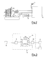
- a machine for making ice chips that comprises a freezing chamber 21 supplied with water from a hydraulic circuit 22, an evaporator 23 of a refrigerating circuit 27 associated with the chamber 21 for cooling and consequently transforming into ice the water in the chamber 21, a motorized screw 24 made to rotate inside the chamber 21 for conveying the ice as it is formed toward a delivery mouth 25 in the proximity of a container for collecting the ice, not shown, and a motorization unit 26 of the screw 24.
- the motorization unit 26 of the screw 24 comprises a motor 40 that has a rotor part 4 to which there is applied a magnet 5 and a stator part 3 to which there are applied a first and a second sensor 1, 2, in the specific case, Hall sensors, for detecting the passage of the magnet 5 during the rotation of the rotor part 4 with respect to the stator part 3.
- the sensors 1 and 2 are connected to an electronic circuit 6 for controlling the speed and direction of rotation of the rotor part 4.
- the electronic control circuit 6 comprises a comparator 9 across an input of which there are applied voltage impulses from the first and from the second sensor 1, 2 to be compared with a reference voltage present across its other input.
- a microprocessor 12 which comprises an input register 13 for the temporary storage of the values at the outputs from the comparator 9, a RAM memory 15 in which the digital values from the register 13 are stored, an EPROM memory 16 in which the program data indicative of the optimum speed of the motor and of its direction of rotation have previously been stored, a central processing unit 14 suitable for making the comparison between the digital values in the RAM memory 15 and in the EPROM 16 and an output register 17 for storing the result of the comparison made by the unit 14.
- a timer 33 which has the object of delaying by a predetermined length of time the re-activation of the machine when the correct conditions of speed and direction of rotation of the motor have been restored.
- the optical signal unit 7 To the output from the microprocessor 14 there are connected the optical signal unit 7 and a power circuit 18 suitable for operating the machine's power unit 8.
- the hydraulic circuit 22 supplies water to the freezing chamber 21 for its transformation into ice thanks to the evaporator 23.
- the screw 24 made to rotate by the motorization unit 26 pushes the ice as it is formed towards the delivery mouth 25.
- the magnet 5 passes in succession under the sensors 1 and 2.
- the latter generate a first and a second series of impulses 11, 12, respectively, represented in Fig. 5, where the x-axis indicates the times at which the impluses themselves are generated.
- Each impluse passes through the comparator 9, where it is compared with the reference voltage present across its other input, and is then introduced into the input register 13 of the microprocessor 12 to then pass into the RAM 15 and be compared through the processing unit 14 with the program data previously stored in the EPROM.
- the processing unit 14 On the basis of the distances and of the phase displacement angles between successive impulses, the processing unit 14 is in a position of detecting changes in the speed and direction of rotation of the rotor part 4 with respect to the stator part 3. In this case the processing unit 14 sends a signal that causes the signal unit 7 to start flashing and, through the power circuit 18 and the power device 8, the instantaneous stoppage of the machine's operation. At the same time, inside the microprocessor 12 the timer 33 is started and, after a given time, say, equal to a few hours, it causes the re-activation of the machine's operation.
- the timer 33 prevents for a given time any comparison from being made between the digitalized values originating from the sensors 1 and 2 and the program data stored in the EPROM 16 to allow the moving parts to reach operating speeds.
Landscapes
- Engineering & Computer Science (AREA)
- Physics & Mathematics (AREA)
- Mechanical Engineering (AREA)
- Thermal Sciences (AREA)
- General Engineering & Computer Science (AREA)
- General Physics & Mathematics (AREA)
- Control Of Electric Motors In General (AREA)
- Production, Working, Storing, Or Distribution Of Ice (AREA)
Applications Claiming Priority (2)
| Application Number | Priority Date | Filing Date | Title |
|---|---|---|---|
| IT2143890 | 1990-09-12 | ||
| IT02143890A IT1244315B (it) | 1990-09-12 | 1990-09-12 | Dispositivo elettronico di controllo della velocita' e senso di rotazione di un motore per macchina per la produzione di ghiaccio in scaglie |
Publications (1)
| Publication Number | Publication Date |
|---|---|
| EP0475500A1 true EP0475500A1 (fr) | 1992-03-18 |
Family
ID=11181799
Family Applications (1)
| Application Number | Title | Priority Date | Filing Date |
|---|---|---|---|
| EP91202186A Withdrawn EP0475500A1 (fr) | 1990-09-12 | 1991-08-28 | Circuit électronique pour contrôler la vitesse et la direction de rotation d'un moteur de machine à fabriquer des flocons de glace |
Country Status (7)
| Country | Link |
|---|---|
| EP (1) | EP0475500A1 (fr) |
| AU (1) | AU8357891A (fr) |
| FI (1) | FI914172A7 (fr) |
| IE (1) | IE913198A1 (fr) |
| IT (1) | IT1244315B (fr) |
| PT (1) | PT98936A (fr) |
| ZA (1) | ZA916954B (fr) |
Cited By (4)
| Publication number | Priority date | Publication date | Assignee | Title |
|---|---|---|---|---|
| EP1251321A3 (fr) * | 2001-04-19 | 2002-12-18 | Hoshizaki Denki Kabushiki Kaisha | Machine de fabrication de glace du type à vis sans fin |
| EP1486744A1 (fr) * | 2003-06-11 | 2004-12-15 | Hoshizaki Denki Kabushiki Kaisha | Dispositif de protection d'une machine de fabrication de glace à vis sans fin |
| EP1437565A4 (fr) * | 2001-09-13 | 2005-09-07 | Hoshizaki Electric Co Ltd | Machine a glace a foret |
| US11596783B2 (en) | 2018-03-06 | 2023-03-07 | Indiana University Research & Technology Corporation | Blood pressure powered auxiliary pump |
Citations (4)
| Publication number | Priority date | Publication date | Assignee | Title |
|---|---|---|---|---|
| CH554029A (fr) * | 1972-02-16 | 1974-09-13 | Mcquay Perfex Inc | Distributeur de glace. |
| US4228396A (en) * | 1978-05-26 | 1980-10-14 | Dataproducts Corporation | Electronic tachometer and combined brushless motor commutation and tachometer system |
| EP0296699A2 (fr) * | 1987-04-16 | 1988-12-28 | Matsushita Electric Industrial Co., Ltd. | Système de régulation à base de microprocesseur en particulier pour un moteur |
| EP0380707A1 (fr) * | 1988-08-11 | 1990-08-08 | Fanuc Ltd. | Procede de detection de choc/d'arret d'entrainement dans une machine mue par un servomoteur |
-
1990
- 1990-09-12 IT IT02143890A patent/IT1244315B/it active IP Right Grant
-
1991
- 1991-08-28 EP EP91202186A patent/EP0475500A1/fr not_active Withdrawn
- 1991-09-02 ZA ZA916954A patent/ZA916954B/xx unknown
- 1991-09-03 AU AU83578/91A patent/AU8357891A/en not_active Abandoned
- 1991-09-04 FI FI914172A patent/FI914172A7/fi not_active Application Discontinuation
- 1991-09-11 PT PT98936A patent/PT98936A/pt not_active Application Discontinuation
- 1991-09-11 IE IE319891A patent/IE913198A1/en unknown
Patent Citations (4)
| Publication number | Priority date | Publication date | Assignee | Title |
|---|---|---|---|---|
| CH554029A (fr) * | 1972-02-16 | 1974-09-13 | Mcquay Perfex Inc | Distributeur de glace. |
| US4228396A (en) * | 1978-05-26 | 1980-10-14 | Dataproducts Corporation | Electronic tachometer and combined brushless motor commutation and tachometer system |
| EP0296699A2 (fr) * | 1987-04-16 | 1988-12-28 | Matsushita Electric Industrial Co., Ltd. | Système de régulation à base de microprocesseur en particulier pour un moteur |
| EP0380707A1 (fr) * | 1988-08-11 | 1990-08-08 | Fanuc Ltd. | Procede de detection de choc/d'arret d'entrainement dans une machine mue par un servomoteur |
Non-Patent Citations (2)
| Title |
|---|
| ELECTRONICS INTERNATIONAL, vol. 53, no. 19, August 1980, page 176, New York, US; A.L. EQUIZABAL: "Hall-effect tachometer senses speed, direction of rotation" * |
| PATENT ABSTRACTS OF JAPAN, vol. 8, no. 142 (E-254)[1579], 3rd July 1984; & JP-A-59 50 784 (MATSUSHITA DENKI SANGYO K.K.) 23-03-1984 * |
Cited By (5)
| Publication number | Priority date | Publication date | Assignee | Title |
|---|---|---|---|---|
| EP1251321A3 (fr) * | 2001-04-19 | 2002-12-18 | Hoshizaki Denki Kabushiki Kaisha | Machine de fabrication de glace du type à vis sans fin |
| US6609387B2 (en) | 2001-04-19 | 2003-08-26 | Hoshizaki Denki Kabushiki Kaisha | Auger type ice making machine |
| EP1437565A4 (fr) * | 2001-09-13 | 2005-09-07 | Hoshizaki Electric Co Ltd | Machine a glace a foret |
| EP1486744A1 (fr) * | 2003-06-11 | 2004-12-15 | Hoshizaki Denki Kabushiki Kaisha | Dispositif de protection d'une machine de fabrication de glace à vis sans fin |
| US11596783B2 (en) | 2018-03-06 | 2023-03-07 | Indiana University Research & Technology Corporation | Blood pressure powered auxiliary pump |
Also Published As
| Publication number | Publication date |
|---|---|
| AU8357891A (en) | 1992-03-19 |
| FI914172A0 (fi) | 1991-09-04 |
| IT9021438A1 (it) | 1992-03-12 |
| FI914172L (fi) | 1992-03-13 |
| IE913198A1 (en) | 1992-02-25 |
| IT1244315B (it) | 1994-07-08 |
| IT9021438A0 (it) | 1990-09-12 |
| FI914172A7 (fi) | 1992-03-13 |
| ZA916954B (en) | 1992-05-27 |
| PT98936A (pt) | 1994-01-31 |
Similar Documents
| Publication | Publication Date | Title |
|---|---|---|
| US4585980A (en) | Windshield wiper control | |
| US4964258A (en) | Packaging article inclusion-proofing device for end-sealing mechanism | |
| EP0475500A1 (fr) | Circuit électronique pour contrôler la vitesse et la direction de rotation d'un moteur de machine à fabriquer des flocons de glace | |
| US4790526A (en) | Method and apparatus for controlling the rotation of a bill accumulating wheel | |
| US5726881A (en) | Centrifugal apparatus with overspeed protection | |
| US5233292A (en) | Speed detector device for elevator | |
| US4582506A (en) | Method for the production control on bag machines | |
| US6198788B1 (en) | Encoder test apparatus and method | |
| US4903193A (en) | Runaway detecting system for CPU | |
| IE913200A1 (en) | Electronic device for controlling the level of the ice in a¹collecting container of a machine for making ice chips | |
| JPH0232799A (ja) | 負荷角調整装置を有する電気ステツプモータ及びその作動方法 | |
| US4591770A (en) | Numerical controller | |
| US5442267A (en) | Device for controlling the reverse rotation of a motor and method of judging time point where the motor is actually rotated in a reverse direction | |
| US4742245A (en) | Method for controlling automatic door in turning-on time of its power supply | |
| EP0271903A2 (fr) | Dispositif pour visser des fixations taraudées | |
| CA2103321A1 (fr) | Systeme autoreglable de positionnement de moteur et methode connexe | |
| US5941359A (en) | Positioning apparatus | |
| JP2723757B2 (ja) | モータ制御装置 | |
| EP0117494A1 (fr) | Appareil de régulation de vitesse pour un moteur pas-à-pas | |
| GB2198983A (en) | Method of and apparatus for tightening screw-threaded fasteners | |
| JP2690955B2 (ja) | 物品の整列・集積装置 | |
| US4739238A (en) | Rotating mechanism control system | |
| JP2541809B2 (ja) | エンコ−ダ欠相検出装置 | |
| JP2629220B2 (ja) | 移動機械の走行制御方法 | |
| JP2769067B2 (ja) | モータ制御装置 |
Legal Events
| Date | Code | Title | Description |
|---|---|---|---|
| PUAI | Public reference made under article 153(3) epc to a published international application that has entered the european phase |
Free format text: ORIGINAL CODE: 0009012 |
|
| AK | Designated contracting states |
Kind code of ref document: A1 Designated state(s): AT BE CH DE DK ES FR GB GR IT LI LU NL SE |
|
| 17P | Request for examination filed |
Effective date: 19920902 |
|
| 17Q | First examination report despatched |
Effective date: 19931210 |
|
| STAA | Information on the status of an ep patent application or granted ep patent |
Free format text: STATUS: THE APPLICATION IS DEEMED TO BE WITHDRAWN |
|
| 18D | Application deemed to be withdrawn |
Effective date: 19940421 |