EP0475591A1 - Verfahren zur Produktion von hochreinem Gas - Google Patents
Verfahren zur Produktion von hochreinem Gas Download PDFInfo
- Publication number
- EP0475591A1 EP0475591A1 EP91307437A EP91307437A EP0475591A1 EP 0475591 A1 EP0475591 A1 EP 0475591A1 EP 91307437 A EP91307437 A EP 91307437A EP 91307437 A EP91307437 A EP 91307437A EP 0475591 A1 EP0475591 A1 EP 0475591A1
- Authority
- EP
- European Patent Office
- Prior art keywords
- pressure
- process according
- gas
- feed gas
- production
- Prior art date
- Legal status (The legal status is an assumption and is not a legal conclusion. Google has not performed a legal analysis and makes no representation as to the accuracy of the status listed.)
- Granted
Links
- 238000004519 manufacturing process Methods 0.000 title claims abstract description 58
- 239000007789 gas Substances 0.000 claims abstract description 130
- 238000000034 method Methods 0.000 claims abstract description 67
- 239000011261 inert gas Substances 0.000 claims abstract description 15
- 239000012535 impurity Substances 0.000 claims description 32
- IJGRMHOSHXDMSA-UHFFFAOYSA-N Atomic nitrogen Chemical compound N#N IJGRMHOSHXDMSA-UHFFFAOYSA-N 0.000 claims description 15
- 239000003463 adsorbent Substances 0.000 claims description 14
- QVGXLLKOCUKJST-UHFFFAOYSA-N atomic oxygen Chemical compound [O] QVGXLLKOCUKJST-UHFFFAOYSA-N 0.000 claims description 11
- 239000001301 oxygen Substances 0.000 claims description 11
- 229910052760 oxygen Inorganic materials 0.000 claims description 11
- 239000000463 material Substances 0.000 claims description 6
- 229910052757 nitrogen Inorganic materials 0.000 claims description 6
- 229910001873 dinitrogen Inorganic materials 0.000 claims description 3
- 230000001172 regenerating effect Effects 0.000 claims 2
- 239000000047 product Substances 0.000 abstract description 52
- 238000001179 sorption measurement Methods 0.000 abstract description 8
- 239000006227 byproduct Substances 0.000 abstract description 2
- 230000008929 regeneration Effects 0.000 description 15
- 238000011069 regeneration method Methods 0.000 description 15
- 230000000052 comparative effect Effects 0.000 description 11
- OKTJSMMVPCPJKN-UHFFFAOYSA-N Carbon Chemical compound [C] OKTJSMMVPCPJKN-UHFFFAOYSA-N 0.000 description 8
- 239000002808 molecular sieve Substances 0.000 description 7
- URGAHOPLAPQHLN-UHFFFAOYSA-N sodium aluminosilicate Chemical compound [Na+].[Al+3].[O-][Si]([O-])=O.[O-][Si]([O-])=O URGAHOPLAPQHLN-UHFFFAOYSA-N 0.000 description 7
- 229910052799 carbon Inorganic materials 0.000 description 6
- 239000002912 waste gas Substances 0.000 description 5
- 238000000926 separation method Methods 0.000 description 4
- 238000013022 venting Methods 0.000 description 4
- 239000000126 substance Substances 0.000 description 3
- XKRFYHLGVUSROY-UHFFFAOYSA-N Argon Chemical compound [Ar] XKRFYHLGVUSROY-UHFFFAOYSA-N 0.000 description 2
- CURLTUGMZLYLDI-UHFFFAOYSA-N Carbon dioxide Chemical compound O=C=O CURLTUGMZLYLDI-UHFFFAOYSA-N 0.000 description 2
- GQPLMRYTRLFLPF-UHFFFAOYSA-N Nitrous Oxide Chemical compound [O-][N+]#N GQPLMRYTRLFLPF-UHFFFAOYSA-N 0.000 description 2
- 230000003197 catalytic effect Effects 0.000 description 2
- 238000002485 combustion reaction Methods 0.000 description 2
- 238000010586 diagram Methods 0.000 description 2
- 239000000203 mixture Substances 0.000 description 2
- 239000008188 pellet Substances 0.000 description 2
- 238000010926 purge Methods 0.000 description 2
- 229920006395 saturated elastomer Polymers 0.000 description 2
- 239000010457 zeolite Substances 0.000 description 2
- UGFAIRIUMAVXCW-UHFFFAOYSA-N Carbon monoxide Chemical compound [O+]#[C-] UGFAIRIUMAVXCW-UHFFFAOYSA-N 0.000 description 1
- VYPSYNLAJGMNEJ-UHFFFAOYSA-N Silicium dioxide Chemical class O=[Si]=O VYPSYNLAJGMNEJ-UHFFFAOYSA-N 0.000 description 1
- 229910021536 Zeolite Inorganic materials 0.000 description 1
- 239000002250 absorbent Substances 0.000 description 1
- 230000002745 absorbent Effects 0.000 description 1
- 150000001399 aluminium compounds Chemical class 0.000 description 1
- 229940077746 antacid containing aluminium compound Drugs 0.000 description 1
- 238000013459 approach Methods 0.000 description 1
- 229910052786 argon Inorganic materials 0.000 description 1
- 239000001569 carbon dioxide Substances 0.000 description 1
- 229910002092 carbon dioxide Inorganic materials 0.000 description 1
- 229910002091 carbon monoxide Inorganic materials 0.000 description 1
- 238000007084 catalytic combustion reaction Methods 0.000 description 1
- 238000010924 continuous production Methods 0.000 description 1
- 125000004122 cyclic group Chemical group 0.000 description 1
- 230000007423 decrease Effects 0.000 description 1
- 230000001419 dependent effect Effects 0.000 description 1
- 238000003795 desorption Methods 0.000 description 1
- HNPSIPDUKPIQMN-UHFFFAOYSA-N dioxosilane;oxo(oxoalumanyloxy)alumane Chemical compound O=[Si]=O.O=[Al]O[Al]=O HNPSIPDUKPIQMN-UHFFFAOYSA-N 0.000 description 1
- 230000000694 effects Effects 0.000 description 1
- 239000003546 flue gas Substances 0.000 description 1
- 239000000446 fuel Substances 0.000 description 1
- 239000008246 gaseous mixture Substances 0.000 description 1
- 239000001307 helium Substances 0.000 description 1
- 229910052734 helium Inorganic materials 0.000 description 1
- SWQJXJOGLNCZEY-UHFFFAOYSA-N helium atom Chemical compound [He] SWQJXJOGLNCZEY-UHFFFAOYSA-N 0.000 description 1
- 239000001257 hydrogen Substances 0.000 description 1
- 229910052739 hydrogen Inorganic materials 0.000 description 1
- 125000004435 hydrogen atom Chemical class [H]* 0.000 description 1
- 238000002347 injection Methods 0.000 description 1
- 239000007924 injection Substances 0.000 description 1
- 238000012986 modification Methods 0.000 description 1
- 230000004048 modification Effects 0.000 description 1
- 239000003345 natural gas Substances 0.000 description 1
- 239000001272 nitrous oxide Substances 0.000 description 1
- 238000000746 purification Methods 0.000 description 1
- 239000012264 purified product Substances 0.000 description 1
- 238000010998 test method Methods 0.000 description 1
- 238000011144 upstream manufacturing Methods 0.000 description 1
Images



Classifications
-
- B—PERFORMING OPERATIONS; TRANSPORTING
- B01—PHYSICAL OR CHEMICAL PROCESSES OR APPARATUS IN GENERAL
- B01D—SEPARATION
- B01D53/00—Separation of gases or vapours; Recovering vapours of volatile solvents from gases; Chemical or biological purification of waste gases, e.g. engine exhaust gases, smoke, fumes, flue gases, aerosols
- B01D53/02—Separation of gases or vapours; Recovering vapours of volatile solvents from gases; Chemical or biological purification of waste gases, e.g. engine exhaust gases, smoke, fumes, flue gases, aerosols by adsorption, e.g. preparative gas chromatography
-
- B—PERFORMING OPERATIONS; TRANSPORTING
- B01—PHYSICAL OR CHEMICAL PROCESSES OR APPARATUS IN GENERAL
- B01D—SEPARATION
- B01D53/00—Separation of gases or vapours; Recovering vapours of volatile solvents from gases; Chemical or biological purification of waste gases, e.g. engine exhaust gases, smoke, fumes, flue gases, aerosols
- B01D53/02—Separation of gases or vapours; Recovering vapours of volatile solvents from gases; Chemical or biological purification of waste gases, e.g. engine exhaust gases, smoke, fumes, flue gases, aerosols by adsorption, e.g. preparative gas chromatography
- B01D53/04—Separation of gases or vapours; Recovering vapours of volatile solvents from gases; Chemical or biological purification of waste gases, e.g. engine exhaust gases, smoke, fumes, flue gases, aerosols by adsorption, e.g. preparative gas chromatography with stationary adsorbents
- B01D53/047—Pressure swing adsorption
-
- B—PERFORMING OPERATIONS; TRANSPORTING
- B01—PHYSICAL OR CHEMICAL PROCESSES OR APPARATUS IN GENERAL
- B01D—SEPARATION
- B01D2253/00—Adsorbents used in seperation treatment of gases and vapours
- B01D2253/10—Inorganic adsorbents
- B01D2253/102—Carbon
-
- B—PERFORMING OPERATIONS; TRANSPORTING
- B01—PHYSICAL OR CHEMICAL PROCESSES OR APPARATUS IN GENERAL
- B01D—SEPARATION
- B01D2253/00—Adsorbents used in seperation treatment of gases and vapours
- B01D2253/10—Inorganic adsorbents
- B01D2253/104—Alumina
-
- B—PERFORMING OPERATIONS; TRANSPORTING
- B01—PHYSICAL OR CHEMICAL PROCESSES OR APPARATUS IN GENERAL
- B01D—SEPARATION
- B01D2253/00—Adsorbents used in seperation treatment of gases and vapours
- B01D2253/10—Inorganic adsorbents
- B01D2253/106—Silica or silicates
-
- B—PERFORMING OPERATIONS; TRANSPORTING
- B01—PHYSICAL OR CHEMICAL PROCESSES OR APPARATUS IN GENERAL
- B01D—SEPARATION
- B01D2253/00—Adsorbents used in seperation treatment of gases and vapours
- B01D2253/10—Inorganic adsorbents
- B01D2253/106—Silica or silicates
- B01D2253/108—Zeolites
-
- B—PERFORMING OPERATIONS; TRANSPORTING
- B01—PHYSICAL OR CHEMICAL PROCESSES OR APPARATUS IN GENERAL
- B01D—SEPARATION
- B01D2256/00—Main component in the product gas stream after treatment
- B01D2256/10—Nitrogen
-
- B—PERFORMING OPERATIONS; TRANSPORTING
- B01—PHYSICAL OR CHEMICAL PROCESSES OR APPARATUS IN GENERAL
- B01D—SEPARATION
- B01D2259/00—Type of treatment
- B01D2259/40—Further details for adsorption processes and devices
- B01D2259/40011—Methods relating to the process cycle in pressure or temperature swing adsorption
- B01D2259/40058—Number of sequence steps, including sub-steps, per cycle
- B01D2259/40067—Seven
-
- B—PERFORMING OPERATIONS; TRANSPORTING
- B01—PHYSICAL OR CHEMICAL PROCESSES OR APPARATUS IN GENERAL
- B01D—SEPARATION
- B01D2259/00—Type of treatment
- B01D2259/40—Further details for adsorption processes and devices
- B01D2259/40011—Methods relating to the process cycle in pressure or temperature swing adsorption
- B01D2259/40058—Number of sequence steps, including sub-steps, per cycle
- B01D2259/40069—Eight
-
- B—PERFORMING OPERATIONS; TRANSPORTING
- B01—PHYSICAL OR CHEMICAL PROCESSES OR APPARATUS IN GENERAL
- B01D—SEPARATION
- B01D2259/00—Type of treatment
- B01D2259/40—Further details for adsorption processes and devices
- B01D2259/40011—Methods relating to the process cycle in pressure or temperature swing adsorption
- B01D2259/40058—Number of sequence steps, including sub-steps, per cycle
- B01D2259/40071—Nine
-
- B—PERFORMING OPERATIONS; TRANSPORTING
- B01—PHYSICAL OR CHEMICAL PROCESSES OR APPARATUS IN GENERAL
- B01D—SEPARATION
- B01D2259/00—Type of treatment
- B01D2259/40—Further details for adsorption processes and devices
- B01D2259/40011—Methods relating to the process cycle in pressure or temperature swing adsorption
- B01D2259/40058—Number of sequence steps, including sub-steps, per cycle
- B01D2259/40073—Ten
Definitions
- the present invention relates to the production of an inert product gas from a feed gas containing at least one inert gas and impurities, utilizing pressure swing adsorption techniques. More particularly, this invention relates to a cyclic process wherein the treatment zone is repressurized to production pressure either by feed gas alone fed in an initial slow stage followed by a rapid second stage, or by production gas and feed gas with the feed gas being introduced in a one stage profile or in a two stage profile as described above.
- Adsorption techniques have been used in the separation and in the production of a variety of gases including hydrogen, helium, argon, carbon monoxide, carbon dioxide, nitrous oxide, oxygen, and nitrogen.
- Feed gases useful in these adsorption separations include air; refinery off-gases; and land-fill, flue, and natural gases.
- FIGS. 1-3 Pressure swing adsorption (PSA) processes typically involve the cyclical pressurization, production, and regeneration of adsorbent beds or treatment zones to achieve a product of a specified purity.
- the pressurization step is usually carried out at a constant rate.
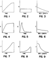
- FIGS. 1-3 This type of system is graphically illustrated in FIGS. 1-3.
- FIG. 1 represents a constant pressure pressurization step.
- FIG. 2 corresponds to the feed flow rate corresponding to the pressurization history in FIG. 1.
- FIG. 3 represents the hypothetical concentration profile of the impurities in the interstitial gas at the end of the pressurization step corresponding to FIG. 1, as a function of bed length.
- the feed rate for the constant pressure history is flat, and therefore, the final concentration profile should be higher in purity at the production end and lower at the injection end.
- a catalytic combustion unit is occasionally combined with a PSA plant when very low oxygen concentration is required.
- the PSA plant is operated to produce inert gas with oxygen concentrations between 10,000 and 1,000 vpm (1.0 and 0.1 percent, respectively) which is then combusted to produce a final inert gas containing 100 vpm or less of oxygen.
- This operation is costly, however, as the catalytic units and the fuel used in the combustion are expensive. Furthermore, it is necessary to remove the combustion products from the effluent of the catalytic unit.
- Leitgeb U.S. Patent No. 4,256,465, offsets the initial low purity surge of product gas of a typical constant pressurization PSA system by slowing the PSA process concentration wave as it moves through the treatment zone. This was done by multi-stage pressurization where the final stage was conducted substantially more slowly than the initial stage. The Leitgeb process actually makes use of a lengthy adsorption time before product is taken though, and does not depend on the pressurization rates.
- FIGS. 4-6 This type of a system is graphically illustrated in FIGS. 4-6.
- FIG. 4 represents a rapid initial pressurization followed by a slow pressurization at the end of the pressurization step.
- FIG. 5 corresponds to the feed flow rate corresponding to the pressurization history in FIG. 4.
- FIG. 6 represents the hypothetical concentration profile of the impurities in the interstitial gas at the end of the pressurization step corresponding to FIG. 4, as a function of bed length.
- the feed rate for this "early" pressure history is initially so fast that the bed comes up to pressure before a lot of the feed gas is adsorbed. Consequently, the resultant final concentration history is flat, and the purity of the initial product is low. Therefore, a PSA plant operating with an early feed history on a given cycle and at specified feed and product rates would produce the lowest purity.
- Japanese Patent Publication No. 63-79714 discloses a three treatment zone merry-go-round PSA system wherein at any given time, two serially connected treatment zones are used for adsorption while a third treatment zone is regenerated.
- the PSA processes of the present invention alleviate the problems of the prior art by the cost-effective production of substantially pure product gas by a two step slow/fast pressurization with feed gas or by product gas pressurization in combination with one step or two step slow/fast feed gas pressurization.
- the process of the present invention in its broadest aspects is directed to the production of a highly purified inert gas through the use of a pressure swing adsorption system in which the treatment zone is repressurized to a production pressure by either a method employing a feed gas alone or in combination with the product gas.
- the present invention relates to a process for the production of highly purified inert product gas from a feed gas containing the inert gas and impurities comprising
- the pressurization step (a) comprises (i) introducing the product gas into the outlet region to raise the pressure of the treatment zone to a first intermediate pressure less than the production pressure and (ii) (1) first slowly introducing the feed gas for an initial period into the inlet region to raise the pressure of the treatment zone to a second intermediate pressure which is less than the production pressure but greater than the pressure of the treatment zone after it has optionally been regenerated; and subsequently (2) rapidly introducing the same or a different feed gas for a period less than the initial period into the inlet region to raise the pressure of the treatment zone to the production pressure; and optionally (3) introducing the same or a different feed gas as in step (1) or (2) for a further period to raise further the pressure of said treatment zone.
- the step of removing the product gas from the outlet region preferably comprises (i) simultaneously removing the inert product gas from the outlet region; (ii) sequentially removing the inert product from the outlet region; or (iii) a combination of (i) and (ii).
- the process of the present invention preferably includes the regeneration of the treatment zone to remove impurities therefrom which is particularly desired for the continuous production of product gas.
- any of these processes may be performed in a single treatment zone or in a plurality of treatment zones.
- at least one of the treatment zones is used to remove the impurities from the feed gas and at least one of the treatment zones is simultaneously regenerated to remove impurities therein to thereby allow the process to run continuously.
- the present invention is directed to a PSA system wherein high purity inert gas is produced by passing a feed gas through a treatment zone, adsorbing a majority of the impurities from the gas, and withdrawing a purified product gas from the treatment zone. It has been found with the pressurization techniques of the present invention, that the efficiency of the PSA system in producing the high-purity inert product gas is substantially increased.
- the PSA processes of the present invention in general, can be carried out using any adsorbent material having selectivity for one or more of the impurities of the gaseous feed mixture.
- Suitable adsorbents include zeolite molecular sieves, zeolites, activated carbon, carbon molecular sieves, silica compounds, aluminium compounds and the like.
- the difference between the amounts of the impurities adsorbed at the lowest and highest pressures during the PSA cycle determine the efficiency of the separation.
- the treatment zone may contain one or more different adsorbents.
- the present processes may be conducted either batchwise or continuously.
- the treatment zone must be periodically regenerated by purging the accumulated adsorbed impurities if the treatment zone is to be reused.
- purification of the feed gas must be stopped during regeneration of the treatment zone.
- a continuous system a plurality of treatment zones are used with at least one treatment zone producing purified gas while at least one other treatment zone is undergoing regeneration.
- the feed gas pressurization is carried out in two stages, the first stage comprising a slow introduction of feed gas for an initial period into the inlet region of the treatment zone in order to raise the pressure of the treatment zone to an intermediate pressure.
- the intermediate pressure is less than the production pressure of the system yet greater than the pressure of the treatment zone after regeneration.
- the same or different gas is rapidly introduced for a second period, which is less than the initial period, into the inlet region of the treatment zone in order to raise the pressure of the treatment zone to the production pressure.
- This type of "late" pressurization is illustrated by FIG. 7.
- FIG. 8 corresponds to the feed flow rate corresponding to the pressurization history in FIG. 7.
- FIG. 8 corresponds to the feed flow rate corresponding to the pressurization history in FIG. 7.
- a typical full cycle of the PSA unit in the present process with two step late profile feed gas pressurization is as follows:
- FIG. 10 A conventional two zone process with constant pressure feed pressurization is shown schematically in FIG. 10.
- the valves controlling flow of the feed gas into the system, high-pressure product withdrawal and waste gas venting from treatment zones A and B are numbered 1 through 10.
- a full cycle on conventional PSA units as shown in FIG. 10 is as follows:
- Typical timing and valve positions are shown in FIG. 11 using a full cycle time between 120 and 240 seconds..
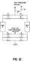
- FIG. 12 An embodiment of the present invention as a two zone PSA process with the equipment necessary for the pressurization techniques of the present invention is shown schematically in FIG. 12.
- the valves controlling flow of feed into the PSA system, product withdrawal, and waste gas venting from treatment zones A and B are numbered 1 through 13.
- a typical full cycle on the PSA unit incorporating two step "late" profile pressuriiation with feed gas in accordance with the present invention is as follows:
- Typical full cycles of two treatment zone processes having feed and product pressurization as embodied in the present invention are as follows: or
- Pressurization in multiple treatment zone systems may also optionally include a zone pressure equalization step either before or after the first stage or step of two stage fast/slow or two step backfill/feed pressurization processes, before the optional third step of a three stage fast/slow/optional continued feed pressurization process, or at the corresponding stages or steps in a combination two step, backfill two stage or three stage fast/slow/optional continued feed pressurization process.
- Equalization pressure is generally higher than regeneration pressure but less than production pressure.
- Regeneration is accomplished by subjecting nearly saturated or saturated treatment zones to a reduced pressure (atmosphere and/or sub-atmospheric pressure) provided by a mechanical vacuum pump, by venting to the atmosphere, by flow of a purge gas containing little or none of the more-readily adsorbed components or by a combination of any of the above.
- a reduced pressure atmosphere and/or sub-atmospheric pressure
- zones A and B contain an adsorbent or combination of adsorbents that selectively remove one or more components from a feed gas stream.
- the valves 1 and 2 control the flow of feed gas to zones A and B, respectively, while the valves 9 and 10 control the flow of product from the two zones. Flow of the desorbed gases during regeneration is allowed by the operation of the valves 5 and 6.
- valves 3, 4, 7, and 8 which are closed during all adsorption and desorption steps, open during the equalization step to allow the flow of gas from the inlet region and/or the outlet region of the zone at high pressure to the inlet region and/or outlet region of the zone at low pressure.
- valves 3, 4, 7, and 8 close, and repressurization is continued. If, for example zone A is to be repressurized while zone B is to be regenerated, valve 6 is opened for venting zone B while product gas is introduced to Bed A through the opening of valves 9, 11, and 12.
- the valve 12 in this schematic is not an actuatable valve like valves 1 through 11, but merely serves to throttle the backflow of product gas so as to control pressurization.
- the flow of feed gas to the conduit connecting the valves 1 and 2 is controlled by a similar throttling valve (not shown in this schematic) to allow for two step slow initial pressurization followed by rapid feed pressurization.
- valves 9, 11, and 12 When the valves 9, 11, and 12 are open, a steady flow of product gas enters the zone for a period of time of between 5 and 10 seconds.
- the zone which at the end of the equalization step was at a pressure between 40 and 50 percent of the production pressure, should finish backfilling at a pressure between 60 and 70 percent of the production pressure.
- valve 11 closes and valve 1 opens to allow the flow of the feed gas to proceed slowly into zone A.
- the flowrate controlled by a throttling valve upstream of the valves 1 and 2 is set to bring the pressure from 40 to 50 percent of the production pressure up to 90 to 100 percent of the production pressure within 70 percent of the remaining production time, typically 60 to 120 seconds for a 240 to 360 second full cycle time.
- FIG. 13 Typical timing and valve positions for this product and feed pressurization process above is shown in FIG. 13. Both combined product and feed pressurization processes use a typical full cycle time between 240 and 480 seconds.
- the combined feed and product pressurization schemes establish multiple regions of varying inert-gas purity in the regenerated treatment zones upon repressurization.
- the region nearest the inlet of the treatment zone (the "first region") has a composition like that of the feed gas.
- the region just above the “first region” (the “second region”) has a purity intermediate that of the feed gas and the product gas.
- the purity of the region above the “second region” (the “third region") is intermediate that of the "second region” and the product gas, and the region nearest the outlet (the “fourth region”) has a purity like that of the product gas.
- Any additional regions of gas purity are introduced into the repressurizing PSA vessel in such a way that the purity of the additional region lies between the purities of its neighbors.
- product pressurization brings a treatment zone to from about 60 to about 70 percent of the production pressure.
- the initial periods of late profile feed gas pressurization typically is from about 75 to about 160 seconds, and feed gas flow rate during the initial period ranges from about 50 to about 120 scfh/cf adsorbent.
- the second period typically is from about 10 to about 70 seconds, and the feed gas flow rate during the secondary period ranges from about 100 to about 350 scfh/cf adsorbent.
- Product pressurization typically lasts from about 5 to about 10 seconds, and flow rate is from about 2.0 to about 5.0 scfh. Production pressure ranges from about 75 to about 150 psig and preferably about 85 psig.
- the optional third stage of feed pressurization may be performed according to any feed history profile and last for any appropriate period. It will simply raise the production pressure further within the above defined production pressure range.
- Regeneration pressure is typically 0 psig
- initializing pressure typically ranges from about 65 to about 135 psig
- secondary period pressure typically ranges from about 75 to about 150 psig
- backfill pressure typically ranges from about 45 to about 105 psig.
- a series of experimental runs was conducted utilizing a PSA unit as illustrated in FIG. 12, a range of cycle times from 240 to 360 seconds operating on the cycle shown in FIG. 13 with the second pressurization step continuing until a production pressure of 85 psig was achieved.
- Regeneration pressure was 0 psig.
- CMS carbon molecular sieve
- the product backfill pressure ranged from 50 to 60 psig.
- a feed gas of compressed air was sent to the PSA treatment zones, from which purified nitrogen product gas was taken at opposite ends and an enriched oxygen waste gas was vented in a countercurrent direction.
- Example 1 A series of runs was conducted following the procedure of Example 1 substituting a PSA unit as illustrated in FIG. 10 operating on the cycle shown in FIG. 11.
- a series of experimental runs was conducted utilizing a PSA unit as illustrated in FIG. 12, a cycle time of 240 seconds operating on the cycle shown in FIG. 13, except that product gas pressurization was omitted and pressurization was done by the slow introduction of feed gas for an initial period until a intermediate pressure less than the production pressure but greater than equalization pressure was reached. Thereafter, the feed gas was introduced rapidly for a second period less than the initial period to raise the system to a production pressure of 85 psig similar to the pressure history of FIG. 7. The regeneration pressure was 0 psig.
- Example 5 A series of runs was conducted following the procedure of Example 5 substituting a PSA unit as illustrated in FIG. 10 operating on the cycle shown in FIG. 11.
- Purified nitrogen product gas was taken at the outlet end and an enriched oxygen white gas was vented in a countercurrent direction.
- Example 8 when compared with Comparative Example 8A*, demonstrates the substantial improvement on plant production and product yield using the combined product and two step "late profile" feed pressurization process of the present invention.
- a series of experimental runs was conducted utilizing a PSA unit and a pressurization step comprising product pressurization and one step feed pressurization, a cycle of 360 seconds, a backfill pressure of from 10 to 20 psig, a production pressure of 85 p sig, a regeneration pressure of 0 psig, and a specific feed of 71 scfh air/cf CMS.
- the adsorbant was carbon molecular sieve.
- a feed gas of air was sent to the PSA treatment zones, from which purified nitrogen gas was taken at the outlet end and an enriched oxygen waste gas was vented in a countercurrent direction.
- Examples 9-11 and Comparative Examples 12*-15* illustrate that both productivity and yield are increased by the method of the present invention and that the effect of backfill does not appear to be determined by the amount of gas adsorbed, but on the purity of the interstitial gas.
- the optimum amount of pressure increase during backfill appears to be 10 psig.
- a series of experimental runs was conducted utilizing a PSA system with a two step feed pressurization having a profile as illustrated in FIG. 8, a cycle time of 240 seconds, a production pressure of 85 psig, a regeneration pressure of 0 psig and a specific range of 0.75.
- the adsorbent was carbon molecular sieve.
Landscapes
- Chemical & Material Sciences (AREA)
- Engineering & Computer Science (AREA)
- Analytical Chemistry (AREA)
- General Chemical & Material Sciences (AREA)
- Oil, Petroleum & Natural Gas (AREA)
- Chemical Kinetics & Catalysis (AREA)
- Separation Of Gases By Adsorption (AREA)
Applications Claiming Priority (3)
| Application Number | Priority Date | Filing Date | Title |
|---|---|---|---|
| US567487 | 1990-08-14 | ||
| US07/567,487 US5082474A (en) | 1990-08-14 | 1990-08-14 | Pressurization psa systems for the production of high purity product gas |
| CA002049507A CA2049507A1 (en) | 1990-08-14 | 1991-08-19 | Pressurization psa systems for the production of high purity product gas |
Publications (2)
| Publication Number | Publication Date |
|---|---|
| EP0475591A1 true EP0475591A1 (de) | 1992-03-18 |
| EP0475591B1 EP0475591B1 (de) | 1996-06-05 |
Family
ID=25674736
Family Applications (1)
| Application Number | Title | Priority Date | Filing Date |
|---|---|---|---|
| EP91307437A Expired - Lifetime EP0475591B1 (de) | 1990-08-14 | 1991-08-13 | Verfahren zur Produktion von hochreinem Gas |
Country Status (7)
| Country | Link |
|---|---|
| US (1) | US5082474A (de) |
| EP (1) | EP0475591B1 (de) |
| JP (1) | JPH04227018A (de) |
| KR (1) | KR940001409B1 (de) |
| CN (1) | CN1060225A (de) |
| AU (1) | AU645588B2 (de) |
| CA (1) | CA2049507A1 (de) |
Cited By (1)
| Publication number | Priority date | Publication date | Assignee | Title |
|---|---|---|---|---|
| WO2003035220A1 (de) * | 2001-10-24 | 2003-05-01 | Linde Ag | Adsorberstation und deren verwendung |
Families Citing this family (6)
| Publication number | Priority date | Publication date | Assignee | Title |
|---|---|---|---|---|
| US5232473A (en) * | 1992-05-07 | 1993-08-03 | The Boc Group, Inc. | Pressure swing adsorption with countercurrent feed pressurization |
| RU2101076C1 (ru) * | 1996-08-08 | 1998-01-10 | Акционерное общество "Гелиймаш" | Адсорбционный концентратор |
| US5827358A (en) * | 1996-11-08 | 1998-10-27 | Impact Mst, Incorporation | Rapid cycle pressure swing adsorption oxygen concentration method and apparatus |
| WO2011139894A1 (en) * | 2010-05-05 | 2011-11-10 | Linde Aktiengesellschaft | Method and apparatus for making a high purity gas |
| US9381460B2 (en) | 2014-09-11 | 2016-07-05 | Air Products And Chemicals, Inc. | Pressure swing adsorption process |
| EP2823872A3 (de) | 2014-09-11 | 2015-05-06 | Air Products And Chemicals, Inc. | Druckwechsel-Adsorptionsverfahren |
Citations (5)
| Publication number | Priority date | Publication date | Assignee | Title |
|---|---|---|---|---|
| DE2038261A1 (de) * | 1970-07-31 | 1972-02-03 | Union Carbide Corp | Selektives Adsorptionsverfahren |
| EP0013680A1 (de) * | 1978-12-27 | 1980-08-06 | Union Carbide Corporation | Adiabatisches Schnell-Druckwechsel-Adsorptionsverfahren und Apparat zur Sauerstofferzeugung mit mehreren Zeolith-Molekularsiebbetten |
| DE3345379A1 (de) * | 1982-06-16 | 1985-06-27 | Bergwerksverband Gmbh, 4300 Essen | Verfahren zur abtrennung und gewinnung von relativ stark an adsorptionsmitteln adsorbierbaren gasen aus ansonsten im wesentlichen nur schwaecher adsorbierbare gase enthaltenden gasgemischen |
| EP0147277A2 (de) * | 1983-12-07 | 1985-07-03 | Calgon Carbon Corporation | Verfahren zur Trennung eines Gasmischungsstroms durch Druckwechseladsorption |
| EP0324171A2 (de) * | 1987-12-29 | 1989-07-19 | Praxair Technology, Inc. | Durchwechseladsorptionsverfahren und System zur Gastrennung |
Family Cites Families (17)
| Publication number | Priority date | Publication date | Assignee | Title |
|---|---|---|---|---|
| DE2260872A1 (de) * | 1972-12-13 | 1974-06-27 | Babcock & Wilcox Ag | Verfahren zur erzeugung von stickstoff zur verwendung als inertgas und vorrichtung dazu |
| GB1449864A (en) * | 1973-10-24 | 1976-09-15 | Boc International Ltd | Adsorption system |
| GB1559325A (en) * | 1976-02-27 | 1980-01-16 | Boc Ltd | Gas separation |
| DE2652486C2 (de) * | 1976-11-18 | 1987-01-08 | Bergwerksverband Gmbh, 4300 Essen | Verfahren zur Gewinnung von stickstoffreichen Gasen aus neben N↓2↓ wenigstens O↓2↓ enthaltenden Gasen, wie z.B. Luft |
| US4256469A (en) * | 1978-11-06 | 1981-03-17 | Linde Aktiengesellschaft | Repressurization technique for pressure swing adsorption |
| DE2932333C2 (de) * | 1979-08-09 | 1986-08-07 | Bergwerksverband Gmbh, 4300 Essen | Verfahren zur adsorptiven Trennung von neben Stickstoff wenigstens Sauerstoff enthaltenden Gasgemischen |
| ZA811931B (en) * | 1980-03-31 | 1982-05-26 | African Oxygen Ltd | Process and apparatus for the separation of gaseous mixture |
| US4376639A (en) * | 1981-12-10 | 1983-03-15 | Calgon Corporation | Novel repressurization of pressure swing adsorption system |
| US4440548A (en) * | 1982-04-19 | 1984-04-03 | Calgon Carbon Corporation | Pressure swing absorption system |
| DE3307974A1 (de) * | 1983-03-07 | 1984-09-13 | Bergwerksverband Gmbh, 4300 Essen | Verfahren zur gewinnung von stickstoff |
| GB2152834B (en) * | 1983-07-23 | 1987-01-28 | Derek Edward Ward | Producing nitrogen from air |
| US4816039A (en) * | 1986-02-24 | 1989-03-28 | The Boc Group, Inc. | PSA multicomponent separation utilizing tank equalization |
| US4756723A (en) * | 1987-03-04 | 1988-07-12 | Air Products And Chemicals, Inc. | Preparation of high purity oxygen |
| US4761165A (en) * | 1987-09-01 | 1988-08-02 | Union Carbide Corporation | Pressure swing adsorption control method and apparatus |
| US4853004A (en) * | 1988-01-20 | 1989-08-01 | The Boc Group, Inc. | Method for densely packing molecular sieve adsorbent beds in a PSA system |
| EP0380723B1 (de) * | 1989-02-01 | 1994-04-06 | Kuraray Chemical Co., Ltd. | Verfahren zur Trennung von Stickstoff enthaltenden Gasen mit einem Druckwechselsystem |
| US4892566A (en) * | 1989-03-22 | 1990-01-09 | Airsep Corporation | Pressure swing adsorption process and system |
-
1990
- 1990-08-14 US US07/567,487 patent/US5082474A/en not_active Expired - Fee Related
-
1991
- 1991-08-08 AU AU81713/91A patent/AU645588B2/en not_active Ceased
- 1991-08-13 EP EP91307437A patent/EP0475591B1/de not_active Expired - Lifetime
- 1991-08-13 JP JP3203027A patent/JPH04227018A/ja active Pending
- 1991-08-13 KR KR1019910013968A patent/KR940001409B1/ko not_active Expired - Lifetime
- 1991-08-13 CN CN91105547A patent/CN1060225A/zh active Pending
- 1991-08-19 CA CA002049507A patent/CA2049507A1/en not_active Abandoned
Patent Citations (5)
| Publication number | Priority date | Publication date | Assignee | Title |
|---|---|---|---|---|
| DE2038261A1 (de) * | 1970-07-31 | 1972-02-03 | Union Carbide Corp | Selektives Adsorptionsverfahren |
| EP0013680A1 (de) * | 1978-12-27 | 1980-08-06 | Union Carbide Corporation | Adiabatisches Schnell-Druckwechsel-Adsorptionsverfahren und Apparat zur Sauerstofferzeugung mit mehreren Zeolith-Molekularsiebbetten |
| DE3345379A1 (de) * | 1982-06-16 | 1985-06-27 | Bergwerksverband Gmbh, 4300 Essen | Verfahren zur abtrennung und gewinnung von relativ stark an adsorptionsmitteln adsorbierbaren gasen aus ansonsten im wesentlichen nur schwaecher adsorbierbare gase enthaltenden gasgemischen |
| EP0147277A2 (de) * | 1983-12-07 | 1985-07-03 | Calgon Carbon Corporation | Verfahren zur Trennung eines Gasmischungsstroms durch Druckwechseladsorption |
| EP0324171A2 (de) * | 1987-12-29 | 1989-07-19 | Praxair Technology, Inc. | Durchwechseladsorptionsverfahren und System zur Gastrennung |
Cited By (3)
| Publication number | Priority date | Publication date | Assignee | Title |
|---|---|---|---|---|
| WO2003035220A1 (de) * | 2001-10-24 | 2003-05-01 | Linde Ag | Adsorberstation und deren verwendung |
| EP1314469A1 (de) * | 2001-10-24 | 2003-05-28 | Linde Aktiengesellschaft | Adsorberstation und deren Verwendung |
| US7156900B2 (en) | 2001-10-24 | 2007-01-02 | Linde Ag | Adsorber station and the use thereof |
Also Published As
| Publication number | Publication date |
|---|---|
| AU645588B2 (en) | 1994-01-20 |
| CN1060225A (zh) | 1992-04-15 |
| CA2049507A1 (en) | 1993-02-20 |
| EP0475591B1 (de) | 1996-06-05 |
| US5082474A (en) | 1992-01-21 |
| JPH04227018A (ja) | 1992-08-17 |
| AU8171391A (en) | 1992-02-20 |
| KR940001409B1 (ko) | 1994-02-23 |
| KR920004020A (ko) | 1992-03-27 |
Similar Documents
| Publication | Publication Date | Title |
|---|---|---|
| US4917710A (en) | Process for recovering oxygen enriched gas | |
| US5882380A (en) | Pressure swing adsorption process with a single adsorbent bed | |
| US4781735A (en) | Enrichment in oxygen gas | |
| FI85953B (fi) | Foerfarande foer framstaellning av en syreprodukt med en renhetsgrad av 95% fraon omgivande luft. | |
| CA1193982A (en) | Process for removing a nitrogen gas from mixture comprising n.sub.2 and co or n.sub.2, co.sub.2 and co | |
| US5395427A (en) | Two stage pressure swing adsorption process which utilizes an oxygen selective adsorbent to produce high purity oxygen from a feed air stream | |
| CA1188231A (en) | Repressurization for pressure swing adsorption system | |
| US4640694A (en) | Adsorption process | |
| US6527830B1 (en) | Pressure swing adsorption process for co-producing nitrogen and oxygen | |
| AU578807B2 (en) | Enhanced pressure swing adsorption process and system | |
| US4690696A (en) | Oxidation of carbonaceous material | |
| US5082474A (en) | Pressurization psa systems for the production of high purity product gas | |
| KR100221006B1 (ko) | 중간 압력 이동을 사용한 질소 압력 스윙 흡착법 | |
| GB2109266A (en) | Pressure swing process for the separation of gas mixtures by adsorption | |
| US20070227354A1 (en) | Oxygen Production Process Using Three-Stage Pressure Swing Adsorption Plants | |
| US5403385A (en) | Serial flow pressure swing adsorption process for gas separation | |
| CA1249229A (en) | Production of oxygen enriched air | |
| US4834956A (en) | Process for the production of high purity argon | |
| JPS6397213A (ja) | 圧力変動吸着分離方法 |
Legal Events
| Date | Code | Title | Description |
|---|---|---|---|
| PUAI | Public reference made under article 153(3) epc to a published international application that has entered the european phase |
Free format text: ORIGINAL CODE: 0009012 |
|
| AK | Designated contracting states |
Kind code of ref document: A1 Designated state(s): AT BE DE FR GB IT NL |
|
| 17P | Request for examination filed |
Effective date: 19920914 |
|
| 17Q | First examination report despatched |
Effective date: 19940214 |
|
| GRAH | Despatch of communication of intention to grant a patent |
Free format text: ORIGINAL CODE: EPIDOS IGRA |
|
| GRAA | (expected) grant |
Free format text: ORIGINAL CODE: 0009210 |
|
| ITF | It: translation for a ep patent filed | ||
| AK | Designated contracting states |
Kind code of ref document: B1 Designated state(s): AT BE DE FR GB IT NL |
|
| PG25 | Lapsed in a contracting state [announced via postgrant information from national office to epo] |
Ref country code: FR Effective date: 19960605 Ref country code: BE Effective date: 19960605 |
|
| REF | Corresponds to: |
Ref document number: 138826 Country of ref document: AT Date of ref document: 19960615 Kind code of ref document: T |
|
| REF | Corresponds to: |
Ref document number: 69120007 Country of ref document: DE Date of ref document: 19960711 |
|
| PG25 | Lapsed in a contracting state [announced via postgrant information from national office to epo] |
Ref country code: DE Effective date: 19960906 |
|
| EN | Fr: translation not filed | ||
| PLBE | No opposition filed within time limit |
Free format text: ORIGINAL CODE: 0009261 |
|
| STAA | Information on the status of an ep patent application or granted ep patent |
Free format text: STATUS: NO OPPOSITION FILED WITHIN TIME LIMIT |
|
| 26N | No opposition filed | ||
| PGFP | Annual fee paid to national office [announced via postgrant information from national office to epo] |
Ref country code: GB Payment date: 20010720 Year of fee payment: 11 Ref country code: AT Payment date: 20010720 Year of fee payment: 11 |
|
| PGFP | Annual fee paid to national office [announced via postgrant information from national office to epo] |
Ref country code: NL Payment date: 20010723 Year of fee payment: 11 |
|
| REG | Reference to a national code |
Ref country code: GB Ref legal event code: IF02 |
|
| PG25 | Lapsed in a contracting state [announced via postgrant information from national office to epo] |
Ref country code: GB Free format text: LAPSE BECAUSE OF NON-PAYMENT OF DUE FEES Effective date: 20020813 Ref country code: AT Free format text: LAPSE BECAUSE OF NON-PAYMENT OF DUE FEES Effective date: 20020813 |
|
| PG25 | Lapsed in a contracting state [announced via postgrant information from national office to epo] |
Ref country code: NL Free format text: LAPSE BECAUSE OF NON-PAYMENT OF DUE FEES Effective date: 20030301 |
|
| GBPC | Gb: european patent ceased through non-payment of renewal fee |
Effective date: 20020813 |
|
| NLV4 | Nl: lapsed or anulled due to non-payment of the annual fee |
Effective date: 20030301 |
|
| PG25 | Lapsed in a contracting state [announced via postgrant information from national office to epo] |
Ref country code: IT Free format text: LAPSE BECAUSE OF NON-PAYMENT OF DUE FEES Effective date: 20050813 |