EP0475690B1 - Papierbehälter und dessen Herstellungsverfahren - Google Patents
Papierbehälter und dessen Herstellungsverfahren Download PDFInfo
- Publication number
- EP0475690B1 EP0475690B1 EP91308164A EP91308164A EP0475690B1 EP 0475690 B1 EP0475690 B1 EP 0475690B1 EP 91308164 A EP91308164 A EP 91308164A EP 91308164 A EP91308164 A EP 91308164A EP 0475690 B1 EP0475690 B1 EP 0475690B1
- Authority
- EP
- European Patent Office
- Prior art keywords
- container
- brim
- paper
- cup
- machine direction
- Prior art date
- Legal status (The legal status is an assumption and is not a legal conclusion. Google has not performed a legal analysis and makes no representation as to the accuracy of the status listed.)
- Expired - Lifetime
Links
- 238000004519 manufacturing process Methods 0.000 title claims description 18
- 239000000463 material Substances 0.000 claims abstract description 49
- 238000000034 method Methods 0.000 claims abstract description 11
- XEEYBQQBJWHFJM-UHFFFAOYSA-N Iron Chemical compound [Fe] XEEYBQQBJWHFJM-UHFFFAOYSA-N 0.000 claims description 4
- 229910052742 iron Inorganic materials 0.000 claims description 2
- 239000000123 paper Substances 0.000 description 106
- 230000015572 biosynthetic process Effects 0.000 description 7
- 239000011324 bead Substances 0.000 description 4
- 238000005259 measurement Methods 0.000 description 4
- 238000005452 bending Methods 0.000 description 3
- 230000001419 dependent effect Effects 0.000 description 3
- 238000005336 cracking Methods 0.000 description 2
- 230000001747 exhibiting effect Effects 0.000 description 2
- 239000007788 liquid Substances 0.000 description 2
- 239000004698 Polyethylene Substances 0.000 description 1
- 230000000712 assembly Effects 0.000 description 1
- 238000000429 assembly Methods 0.000 description 1
- 238000000576 coating method Methods 0.000 description 1
- 238000010276 construction Methods 0.000 description 1
- 230000035622 drinking Effects 0.000 description 1
- 230000000694 effects Effects 0.000 description 1
- 239000002657 fibrous material Substances 0.000 description 1
- 239000012530 fluid Substances 0.000 description 1
- 239000002184 metal Substances 0.000 description 1
- 229910052751 metal Inorganic materials 0.000 description 1
- 239000011087 paperboard Substances 0.000 description 1
- -1 polyethylene Polymers 0.000 description 1
- 229920000573 polyethylene Polymers 0.000 description 1
- 230000000717 retained effect Effects 0.000 description 1
- 238000004513 sizing Methods 0.000 description 1
- 239000012209 synthetic fiber Substances 0.000 description 1
- 229920002994 synthetic fiber Polymers 0.000 description 1
- XLYOFNOQVPJJNP-UHFFFAOYSA-N water Substances O XLYOFNOQVPJJNP-UHFFFAOYSA-N 0.000 description 1
Images

Classifications
-
- B—PERFORMING OPERATIONS; TRANSPORTING
- B31—MAKING ARTICLES OF PAPER, CARDBOARD OR MATERIAL WORKED IN A MANNER ANALOGOUS TO PAPER; WORKING PAPER, CARDBOARD OR MATERIAL WORKED IN A MANNER ANALOGOUS TO PAPER
- B31F—MECHANICAL WORKING OR DEFORMATION OF PAPER, CARDBOARD OR MATERIAL WORKED IN A MANNER ANALOGOUS TO PAPER
- B31F1/00—Mechanical deformation without removing material, e.g. in combination with laminating
- B31F1/008—Shaping of tube ends, e.g. flanging, belling, closing, rim-rolling or corrugating; Fixing elements to tube ends
- B31F1/0087—Rim-rolling
-
- B—PERFORMING OPERATIONS; TRANSPORTING
- B31—MAKING ARTICLES OF PAPER, CARDBOARD OR MATERIAL WORKED IN A MANNER ANALOGOUS TO PAPER; WORKING PAPER, CARDBOARD OR MATERIAL WORKED IN A MANNER ANALOGOUS TO PAPER
- B31B—MAKING CONTAINERS OF PAPER, CARDBOARD OR MATERIAL WORKED IN A MANNER ANALOGOUS TO PAPER
- B31B50/00—Making rigid or semi-rigid containers, e.g. boxes or cartons
- B31B50/74—Auxiliary operations
- B31B50/81—Forming or attaching accessories, e.g. opening devices, closures or tear strings
-
- B—PERFORMING OPERATIONS; TRANSPORTING
- B31—MAKING ARTICLES OF PAPER, CARDBOARD OR MATERIAL WORKED IN A MANNER ANALOGOUS TO PAPER; WORKING PAPER, CARDBOARD OR MATERIAL WORKED IN A MANNER ANALOGOUS TO PAPER
- B31F—MECHANICAL WORKING OR DEFORMATION OF PAPER, CARDBOARD OR MATERIAL WORKED IN A MANNER ANALOGOUS TO PAPER
- B31F1/00—Mechanical deformation without removing material, e.g. in combination with laminating
- B31F1/0003—Shaping by bending, folding, twisting, straightening, flattening or rim-rolling; Shaping by bending, folding or rim-rolling combined with joining; Apparatus therefor
- B31F1/0038—Rim-rolling
-
- B—PERFORMING OPERATIONS; TRANSPORTING
- B65—CONVEYING; PACKING; STORING; HANDLING THIN OR FILAMENTARY MATERIAL
- B65D—CONTAINERS FOR STORAGE OR TRANSPORT OF ARTICLES OR MATERIALS, e.g. BAGS, BARRELS, BOTTLES, BOXES, CANS, CARTONS, CRATES, DRUMS, JARS, TANKS, HOPPERS, FORWARDING CONTAINERS; ACCESSORIES, CLOSURES, OR FITTINGS THEREFOR; PACKAGING ELEMENTS; PACKAGES
- B65D3/00—Rigid or semi-rigid containers having bodies or peripheral walls of curved or partially-curved cross-section made by winding or bending paper without folding along defined lines
- B65D3/02—Rigid or semi-rigid containers having bodies or peripheral walls of curved or partially-curved cross-section made by winding or bending paper without folding along defined lines characterised by shape
- B65D3/06—Rigid or semi-rigid containers having bodies or peripheral walls of curved or partially-curved cross-section made by winding or bending paper without folding along defined lines characterised by shape essentially conical or frusto-conical
-
- B—PERFORMING OPERATIONS; TRANSPORTING
- B31—MAKING ARTICLES OF PAPER, CARDBOARD OR MATERIAL WORKED IN A MANNER ANALOGOUS TO PAPER; WORKING PAPER, CARDBOARD OR MATERIAL WORKED IN A MANNER ANALOGOUS TO PAPER
- B31B—MAKING CONTAINERS OF PAPER, CARDBOARD OR MATERIAL WORKED IN A MANNER ANALOGOUS TO PAPER
- B31B2105/00—Rigid or semi-rigid containers made by assembling separate sheets, blanks or webs
- B31B2105/002—Making boxes characterised by the shape of the blanks from which they are formed
- B31B2105/0022—Making boxes from tubular webs or blanks, e.g. with separate bottoms, including tube or bottom forming operations
-
- B—PERFORMING OPERATIONS; TRANSPORTING
- B31—MAKING ARTICLES OF PAPER, CARDBOARD OR MATERIAL WORKED IN A MANNER ANALOGOUS TO PAPER; WORKING PAPER, CARDBOARD OR MATERIAL WORKED IN A MANNER ANALOGOUS TO PAPER
- B31B—MAKING CONTAINERS OF PAPER, CARDBOARD OR MATERIAL WORKED IN A MANNER ANALOGOUS TO PAPER
- B31B2120/00—Construction of rigid or semi-rigid containers
- B31B2120/002—Construction of rigid or semi-rigid containers having contracted or rolled necks, having shoulders
-
- B—PERFORMING OPERATIONS; TRANSPORTING
- B31—MAKING ARTICLES OF PAPER, CARDBOARD OR MATERIAL WORKED IN A MANNER ANALOGOUS TO PAPER; WORKING PAPER, CARDBOARD OR MATERIAL WORKED IN A MANNER ANALOGOUS TO PAPER
- B31B—MAKING CONTAINERS OF PAPER, CARDBOARD OR MATERIAL WORKED IN A MANNER ANALOGOUS TO PAPER
- B31B50/00—Making rigid or semi-rigid containers, e.g. boxes or cartons
- B31B50/25—Surface scoring
-
- B—PERFORMING OPERATIONS; TRANSPORTING
- B31—MAKING ARTICLES OF PAPER, CARDBOARD OR MATERIAL WORKED IN A MANNER ANALOGOUS TO PAPER; WORKING PAPER, CARDBOARD OR MATERIAL WORKED IN A MANNER ANALOGOUS TO PAPER
- B31B—MAKING CONTAINERS OF PAPER, CARDBOARD OR MATERIAL WORKED IN A MANNER ANALOGOUS TO PAPER
- B31B50/00—Making rigid or semi-rigid containers, e.g. boxes or cartons
- B31B50/26—Folding sheets, blanks or webs
- B31B50/28—Folding sheets, blanks or webs around mandrels, e.g. for forming bottoms
Definitions
- the present invention relates to the manufacture of paper containers such as paper cups, and more particularly to the manufacturing of paper containers having a brim formed about the upper periphery of the container and the machine direction of the paper stock material extending in the circumferential direction of the container.
- Paper container rigidity is defined by that load which when applied to the sidewalls of the container deflects the sidewall of the container inwardly one quarter of an inch (6 mm). Further, this test is carried out at a point on the sidewall of the container which is two-thirds the height of the overall container. In defining the rigidity of a particular container, both dry as well as wet measurements are to be taken. Dry rigidity is measured using an empty container while wet rigidity measurements are taken at a predetermined time period, such as ten minutes after the cup has been filled with water. This rigidity test determines the ability of the container to be picked up by the consumer without collapsing inwardly and spilling the contents when the container is grasped on the sidewall.
- the rigidity of a particular container is affected by the tensile and bending stiffness in both the vertical and circumferential directions of the container.
- One expedient for increasing the rigidity of a paper container is to form a brim about the top of the containers.
- conventional brim curling mechanism utilize complimentary curved dies in which the lower die is first moved upwardly around the upper end of the cup and to the top edge of the cup where it firmly holds the cup top against an upper die. The upper die is then moved downwardly to engage the uppermost edge of the cup between the dies with both of the dies then moving downwardly together to curl the upper edge of the container thereby forming a brim.
- This brim adds significantly to the rigidity of the overall cup structure.
- U.S. Patent No. 3,065,677 issued to Loeser discloses a brim curling mechanism for containers.
- a lower die having a curve forming upper surface is maintained stationary while an upper die having a curve forming lower surface descends downwardly toward the stationary lower die, deflecting the upper edge portion of the cup secured by the lower die and again forming a brim about the upper periphery of the container.
- This brim adds significantly to the overall rigidity of the container.
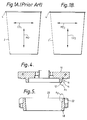
- each of the above-mentioned containers are formed with the machine direction of the paper material aligned in the axial direction of the container and the cross-machine direction of the paper material aligned in the circumferential direction of the container as shown by the arrows MD1 and CD1, respectively.
- Paper when formed using conventional paper manufacturing processes has what is known in the art as a machine direction and a cross-machine direction.
- the machine direction of paper is generally that axis of the paper along which the paper moved as it was being formed.
- the cross-machine direction is perpendicular to the machine direction of the paper and has approximately twice the maximum stretch as that of the machine direction, while the tensile and bending stiffness of the board in the machine direction is greater than that in the cross-machine direction. Therefore, in order to easily form brims 4 about the upper periphery of the cup or container 2, the paper blank used in forming the cup 2 would be positioned as illustrated in Figure 1A.
- U.S. Patent No. 2,473,840 issued to Amberg illustrates a paper container in the form of a conical paper cup being manufactured from a blank which is cut from a paper strip having a machine direction and a cross machine direction. Accordingly, when the conical paper cup is formed, only a limited portion of the upper periphery of the conical paper cup will have the machine direction of the paper blank extending about the circumference of the cup.
- a limited portion of the cross-machine direction of the paper blank extending in the circumferential direction of the conical paper cup will exist with the remaining and substantial portion of the upper periphery being somewhere between the machine direction and the cross-machine direction of the paper blank. Consequently, a brim or bead may be formed about the upper periphery of the conical paper cup using conventional die presses because the overall stretch of the paper about the upper periphery of the conical cup is greater than that of a cup having the entire upper periphery of the cup aligned substantially in the machine direction of the paper blank.
- the rigidity of a conical cup formed in accordance with U.S. Patent No. 2,473,840 will vary depending upon the particular point at which a rigidity test is applied. Therefore, the tensile and bending stiffness of the conical cup will vary significantly about the perimeter resulting in a non-uniform construction.
- containers having the machine direction of the paper material extending in the circumferential direction of the container have been manufactured.
- such containers are formed from a plurality of laminated layers and include metallic end closures.
- Containers formed in the above-mentioned manner are to be used for containing objects, such as blueprints, and, therefore, the significant drawbacks in forming brims or beads about an upper periphery of such containers is not of concern during the above-mentioned manufacturing process because such containers are not for the consumption of liquids by consumers.
- Another object of the present invention is to provide a container having a brim formed about the upper periphery of the container which is more resistant to collapse when grasped by the consumer than conventionally formed containers in that it has been determined that the container rigidity is more strongly dependent on the stiffness of the paper sidewall about its circumference. This being achieved by reorienting the paper material such that the machine direction of the paper material is aligned in the circumferential direction of the cup when formed in accordance with the present invention.
- Another object of the present invention is to provide a brim about the upper periphery of a container having the machine direction of the paper material from which the container is formed aligned in the circumferential direction of the container without presenting vertical cracks in the brim.
- the brims are formed about the upper periphery of the container; however, the width of such brims is limited such that the maximum stretch of the board in the machine direction which is aligned with the circumferential direction of the cup is not exceeded.
- Yet another object of the present invention is to provide a brim about the upper periphery of a container having the machine direction of the paper material from which the container is formed aligned in the circumferential direction of the container with such brim retaining a specified amount of paper material.
- the brim thickness may therefore be readily varied in order to retain as much paper material within the brim as is retained within wider brims of conventional containers.
- the brim width is at least five times that of the caliper of the paper material and not more than a product of the radius of curvature of the container at the brim and twice the uniaxial elongation of the paper material in the machine direction as measured under the conditions experienced during production, e.g.
- the brim width would be at least .05 inches (1.25 mm) and no greater than .075 inches (2.15 mm).
- paper material which is to be taken in its broad sense to mean paper stock material including paperboard and other fibrous material including natural and synthetic fibers wherein machine direction versus cross-machine direction characteristics are created during the formation process.
- conventional paper containers or cups 2 are manufactured with the machine direction of the paper blank being aligned in the vertical or axial direction of the cup as designated by arrow MD1 and the cross-machine direction of the paper blank is aligned in the circumferential direction of the formed cup as illustrated by arrow CD1.
- a bead or brim 4 can be readily formed about the upper periphery of the cup 2 while avoiding the formation of vertical cracks about the brim 4.
- a paper container or cup 2′ formed in accordance with the present invention is illustrated in Figure 1B.
- the cup 2′ is formed of a paper blank having its machine direction aligned in the circumferential direction of the cup 2′ as illustrated by arrow MD2 and the cross-machine direction of the paper blank aligned in the vertical or axial direction of the cup 2′ as illustrated by arrow CD2.
- cups 2′ illustrated in Figure 1B exhibit a greater rigidity against deformation when grasped by the consumer as compared to conventional paper cups 2 in that it has been determined that the container rigidity is more strongly dependent on the stiffness of the paper sidewall about its circumference.
- a brim 4′ is also formed about an upper periphery of the cup 2′ in order to enhance even further the rigidity of the paper cup formed from the re-oriented paper blank as well as to protect the consumer when the contents of the cup are consumed.
- this brim 4′ which if formed by conventional brim forming dies exhibit numerous vertical cracks about the periphery of the brim 4.
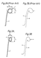
- FIG. 2A illustrates the brim 4 formed about the upper periphery of a conventional cup 2 which is formed by the upper die 6 and lower die 8 which are illustrated in Figure 2B.
- the upper die 6 may be referred to as an iron while the lower die 8 may be referred to as an insert.
- the brim 4 exhibits a width W1 and a thickness T1 which as illustrated in Figure 2A are essentially equal.
- FIG 3A a brim 4′ formed in accordance with the present invention is illustrated. This brim 4′ is formed by the cooperating die members 10 and 18 as illustrated in Figure 3B, the particular structure of which will be described in greater detail herein below.
- the paper material is re-oriented in a manner such that the machine direction of the paper material is aligned in the circumferential direction of the cup 2′, a smaller brim size due to the lower stretch in the machine direction is required.
- the maximum circumferential stretch experienced by conventional cups before cracks become visible in the cup brim depends upon the specific geometry of the cup, but is normally not greater than twice the uniaxial tensile elongation at failure measured in the direction of the strain for a planar sheet of paper stock material.
- Figure 4 illustrates the upper or male die 10 which may be manipulated by conventional brim forming devices such as those illustrated in U.S. Patent Nos. 2,473,836 and 3,065,677 discussed above.
- the upper die 10 includes a lower surface having a flange 12 extending axially therefrom thereby providing a slanted outer surface 14 and an undercut 16, the significance of which will be described in greater detail hereinbelow.
- the lower or female die 18 illustrated in Figure 5 includes an axial bore 20 which receives a cup shell formed from paper material having the machine direction oriented in the circumferential direction of the cup shell with the bore 20 having an upper diameter corresponding to the diameter of the cup shell at the point where the brim 4′ is to be formed, and a lower diameter which corresponds to an adjacent portion of the cup shell in order to secure the cup shell in position during the formation of the brim 4′.
- This lower diameter will be less than that of the upper diameter when forming brims on cups which taper from top to bottom.
- formed about the upper periphery of the bore 20 is a channel 22 which receives paper material during the formation of the brim 4′, the significance of which will be discussed in greater detail hereinbelow.
- Figure 6 illustrates those portions A1 of Figure 4 and A2 of Figure 5 in cooperation with one another in order to form the brim 4′ on a 16-ounce (28.35 g) cup shell having the machine direction of the paper material aligned in the circumferential direction of the cup.
- the radius of curvature R1 of the undercut 16 formed in the lower surface of the die 10 for a 16-ounce cup (28.35 g) would be approximately .
- the radius of curvature R2 of the recess 22 formed in the upper surface of the die 18 would be equal to approximately .0290 inches (0.76 mm) with the central points of the radius of curvature for each of undercut 16 and recess 22 being offset from the point of contact 24 between the upper die 10 and the lower die 18.
- the thickness T2 of the brim 4′ is not dependent upon the circumferential stretch of the paper material used and, consequently, the amount at which the radius of curvatures R1 and R2 are offset from the point of contact 24 will depend upon the particular type of cup being manufactured, and the amount of paper material which is to be used in forming the brim 4′.
- the brim width W2 of the brim 4′ would be at least five times the caliper of the paper material and not more than a product of the radius of curvature of the container at the brim and twice the uniaxial elongation of the paper material in the machine direction as measured under the conditions experienced during production.
- containers having an oval, elliptical or oblong configuration would also be capable of being formed having the machine direction of the paper material extending in the circumferential direction of the container with the brim being conformed to meet the above-mentioned criteria.
- uncoated containers as well as coated containers, i.e., paper coated with polyethylene, wax, or other known coatings.
- a brim was formed about the upper periphery of each of the cups having the machine direction aligned in the axial or vertical direction of the cup by way of conventional brim forming dies while a brim was formed about the upper periphery of each of the cups having the machine direction oriented in the circumferential direction of the cup by dies in accordance with the present invention.
- a rigidity test was conducted on each of the cups by applying a load at a point two-thirds the height of the overall container of the side walls of the container in order to deflect the side walls of the cup inwardly one quarter of an inch. The results of such tests are set forth hereinbelow in Table I.
- the average rigidity was .092 lbs. per .25 inches (6.9 g per mm) greater for cups having the machine direction of the paper material oriented in the circumferential direction of the cup than that of conventional paper cups.
- the rigidity of the paper cups formed in accordance with the present invention were thirteen per cent greater than that of conventional paper cups.
- tests were run on four sets of paper cups, with two sets having the machine direction of the paper material oriented in the vertical or axial direction of the cup with one set having the brim formed with conventional brim forming dies and one set having the brims formed with the dies set forth in accordance with the present invention.
- two sets of cup blanks were formed with the machine direction of the paper material oriented in the circumferential direction of the cup, with one set having brims formed thereon by conventional dies and the other set having brims formed by the dies set forth in accordance with the present invention.
- Twenty cups were formed with each set including five samples. These cups being set forth in Table II. The paper properties of the paper used for all twenty cups is set forth below.
- the average rigidity was .092 lbs per .25 inches (6.9g per mm) greater for cups having the machine direction of the paper material oriented in the circumferential direction of a cup than that of conventional paper cups. This results in an overall increase in rigidity which is approximately thirteen per cent greater than was previously evidenced by conventional paper cups.
- the brim width is at least five times that of the caliper of the paper material and not more than a product of the radius of curvature of the container at the brim and twice the uniaxial elongation of the paper material in the machine direction as measured under the conditions experienced during production, e.g.
- the brim width would be at least .05 inches (1.25 mm) and no greater than .075 inches (1.9 mm).
- a paper blank is cut from either a sheet or roll of paper material in such a manner that the machine direction of the paper material extends in what will be the circumferential direction of a cup formed from the paper blank.
- the blank is then formed into a cup shell and sealed along the vertical seam formed by the overlapping of the ends of the paper blank.
- a bottom is then placed within the lower region of the cup shell and the lower periphery of the cup shell is folded inwardly in order to maintain the bottom of the cup in its predetermined position.
- the cup shell is positioned within the bore 20 of the lower die 18 and positioned below the upper die 10. Once in this position, the upper die will descend downwardly toward the stationary lower die 18 to the position shown in Fig. 6 where the upper surface of the lower die contacts a lower surface of the upper die.
- the leading edge of the cup shell will engage the surface 14 of the flange 12 and the undercut 16, thereby forcing the leading edge of the cup shell outwardly and downwardly along the radius of curvature R1.
- the leading edge of the cup shell will then engage the recess 22 formed in the lower die 18 which will deflect the leading edge of the cup shell inwardly and then upwardly into contact with the outer surface of the cup shell.
- the brim will then be completely formed and when the upper die is withdrawn from the lower die, the brim formed about the upper periphery of the cup shell will not be disturbed. The completely formed cup will then remain in the lower die and moved to the next manufacturing station.
- both the upper and lower dies may be heated in order to more readily shape the brim 4′ about the upper periphery of the cup shell.
- a precurl may be performed on the upper periphery of the cup shell which can be performed at a station prior to the final formation of the brim.
- Containers formed in accordance with the foregoing description may be manufactured by existing manufacturing assemblies with only minor changes being made to the orientation in which the paper blanks are received by the manufacturing assembly and the sizing and shape of the upper and lower dies used to form the brims about the upper periphery of the container.
- the above description is not solely limited to paper cups but may be applied to paper containers having an oval, oblong or elliptical cross section.
Landscapes
- Engineering & Computer Science (AREA)
- Mechanical Engineering (AREA)
- Making Paper Articles (AREA)
- Cartons (AREA)
- Table Devices Or Equipment (AREA)
- Containers Having Bodies Formed In One Piece (AREA)
Claims (18)
- Verfahren zur Herstellung eines Papierbehälters, mit den folgenden Schritten:a) Bereitstellen eines Papierzuschnitts mit einer Maschinenrichtung und einer Maschinen-Querrichtung;b) Formen des genannten Papierzuschnitts zu einem im wesentlichen zylindrischen Körper mit einem ersten und zweiten offenen Ende, wobei die genannte Maschinenrichtung des genannten Papierzuschnitts im wesentlichen auf die Umfangsrichtung des genannten Körpers ausgerichtet ist;c) Verschließen eines der genannten offenen Enden zum Bilden des Bodens des genannten Behälters; undd) Bilden eines Randes um das andere der genannten offenen Enden.
- Verfahren nach Anspruch 1, worin der Schritt der Bildung eines Randes rund um das andere der genannten offenen Enden das Positionieren des genannten zylindrischen Körpers in einer Mittelbohrung eines Untergesenks umfaßt, das eine Aussparung aufweist, die in einer oberen Oberfläche des genannten Untergesenks ausgebildet ist, wobei ein Abschnitt des genannten zylindrischen Körpers sich nach oben über die genannte obere Oberfläche des genannten Untergesenks erstreckt, sowie das Absenken eines oberen Gesenks mit einer Hinterschneidung bzw. Vertiefung in Berührung mit dem genannten Abschnitt des genannten zylindrischen Körpers, der sich über die genannte obere Oberfläche des genannten Untergesenks erstreckt, so daß die genannte Hinterschneidung und die genannte Aussparung zur Bildung des genannten Randes zusammenwirken.
- Verfahren nach Anspruch 2, ferner mit dem Schritt der Vorab-Eindrehung des genannten Abschnitts des genannten zylindrischen Körpers, der sich über die genannte obere Oberfläche des genannten Untergesenks erstreckt, mit einem Eindrehwerkzeug bzw, -eisen vor dem Absenken des genannten Obergesenks.
- Verfahren nach Anspruch 1, worin das genannte Papier eine vorbestimmte Dicke aufweist, und die Breite des genannten Randes nicht kleiner ist als das 5-fache der genannten vorbestimmten Dicke.
- Verfahren nach Anspruch 4, worin die Dicke des genannten Randes größer ist als die genannte Breite des genannten Randes.
- Verfahren nach Anspruch 1, worin die Breite des genannten Randes nicht größer ist als ein Produkt aus dem Krümmungsradius des Behälters am Rand und dem 2-fachen der einachsigen Längung des Papiermaterials in Maschinenrichtung.
- Verfahren nach Anspruch 1, worin der genannte Behälter ein Becher mit kreisförmigem Querschnitt ist.
- Verfahren nach Anspruch 1, worin der genannte Behälter einen elliptischen Querschnitt aufweist.
- Verfahren nach Anspruch 1, worin der genannte Behälter einen länglichen Querschnitt aufweist.
- Verfahren nach Anspruch 1, worin der genannte Behälter einen ovalen Querschnitt aufweist.
- Behälter (2′) aus Papiermaterial, mit den folgenden Merkmalen:
ein im wesentlichen zylindrischer Körper mit einem oberen Ende und einem unteren Ende,
ein Boden, der das genannte untere Ende verschließt, und
ein Rand (4′), der einstückig am genannten oberen Ende des genannten zylindrischen Körpers ausgebildet ist,
worin das genannte Papiermaterial eine Maschinenrichtung (MD₂) und eine Maschinen-Querrichtung (CD₂) aufweist und die genannte Maschinenrichtung des genannten Papiermaterials auf die Umfangsrichtung des genannten Behälters ausgerichtet ist. - Behälter nach Anspruch 11, worin das genannte Papiermaterial eine vorbestimmte Dicke (T₁; T₂) aufweist, und worin die Breite (W₁; W₂) des genannten Randes (4′) nicht kleiner ist als das 5-fache der genannten vorbestimmten Dicke.
- Behälter nach Anspruch 12, worin die Dicke (T₁; T₂) des genannten Randes (4′) größer ist als die genannte Breite (W₁; W₂) des genannten Randes.
- Behälter nach Anspruch 11, worin die Breite (W₁; W₂) des genannten Randes (4′) nicht größer ist als das Produkt aus dem Krümmungsradius (R₁, R₂) des Behälters am Rand und dem 2-fachen der einachsigen Längung des Papiermaterials in Maschinenrichtung.
- Behälter nach Anspruch 11, worin der genannte Behälter (2′) ein Becher mit kreisförmigem Querschnitt ist.
- Behälter nach Anspruch 11, worin der genannte Behälter (2′) einen elliptischen Querschnitt aufweist.
- Behälter nach Anspruch 11, worin der genannte Behälter (2′) einen länglichen Querschnitt aufweist.
- Behälter nach Anspruch 11, worin der genannte Behälter (2′) einen ovalen Querschnitt aufweist.
Applications Claiming Priority (2)
| Application Number | Priority Date | Filing Date | Title |
|---|---|---|---|
| US582770 | 1984-02-23 | ||
| US07/582,770 US5029749A (en) | 1990-09-14 | 1990-09-14 | Paper container and method of making the same |
Publications (2)
| Publication Number | Publication Date |
|---|---|
| EP0475690A1 EP0475690A1 (de) | 1992-03-18 |
| EP0475690B1 true EP0475690B1 (de) | 1994-06-08 |
Family
ID=24330465
Family Applications (1)
| Application Number | Title | Priority Date | Filing Date |
|---|---|---|---|
| EP91308164A Expired - Lifetime EP0475690B1 (de) | 1990-09-14 | 1991-09-06 | Papierbehälter und dessen Herstellungsverfahren |
Country Status (8)
| Country | Link |
|---|---|
| US (1) | US5029749A (de) |
| EP (1) | EP0475690B1 (de) |
| JP (1) | JP2660121B2 (de) |
| AT (1) | ATE106802T1 (de) |
| AU (1) | AU637257B2 (de) |
| CA (1) | CA2051343C (de) |
| DE (1) | DE69102374T2 (de) |
| ES (1) | ES2055545T3 (de) |
Families Citing this family (27)
| Publication number | Priority date | Publication date | Assignee | Title |
|---|---|---|---|---|
| US5184995A (en) * | 1990-12-31 | 1993-02-09 | James River Corporation Of Virginia | Containers and blanks with a curled edge and method of making same |
| US5472402A (en) * | 1994-03-11 | 1995-12-05 | James River Corporation Of Virginia | Preconditioned paperboard containers and method and apparatus for making the same |
| US5544808A (en) * | 1994-03-11 | 1996-08-13 | James River Corporation Of Virginia | Preconditioned paperboard containers |
| US5614661A (en) * | 1994-09-21 | 1997-03-25 | Sweetheart Cup Company Inc. | Apparatus and method for testing containers |
| US5683358A (en) * | 1994-12-29 | 1997-11-04 | Kimberly-Clark Worldwide, Inc. | Applicator for holding and dispensing a substance |
| WO1996020682A1 (en) * | 1994-12-29 | 1996-07-11 | Kimberly-Clark Worldwide, Inc. | An applicator for holding and dispensing a substance |
| WO1997005024A1 (en) * | 1995-07-28 | 1997-02-13 | James River Corporation Of Virginia | Carton having buckle-controlled brim curl and method and blank for forming the same |
| US5752646A (en) * | 1995-07-28 | 1998-05-19 | James River Corporation Of Virginia | Carton having buckle-controlled brim curl and method and blank for forming the same |
| US5868309A (en) * | 1996-07-26 | 1999-02-09 | Fort James Corporation | Carton having buckle-controlled brim curl and method and blank for forming the same |
| US5600102A (en) * | 1996-02-27 | 1997-02-04 | Indium Corporation Of America | Solder preform wrappable around a printed circuit card edge |
| JP3448435B2 (ja) * | 1996-07-01 | 2003-09-22 | 東洋アルミホイルプロダクツ株式会社 | 紙容器及び紙容器の成形方法 |
| ITTO980346A1 (it) * | 1998-04-24 | 1999-10-24 | Ecopack S P A | Procedimento di fabbricazione di contenitori autoportanti di materiale cartaceo per la cottura in forno, la presentazione e la vendita di pro |
| US6120426A (en) * | 1999-02-22 | 2000-09-19 | Sonoco Development, Inc. | Apparatus for forming an outwardly-rolled lip on a cylindrical container body |
| AU1350201A (en) * | 1999-10-27 | 2001-05-08 | Sealright Co., Inc. | Method and apparatus for applying a top curl to non-round containers |
| US6866906B2 (en) * | 2000-01-26 | 2005-03-15 | International Paper Company | Cut resistant paper and paper articles and method for making same |
| AU3306601A (en) * | 2000-01-26 | 2001-08-07 | Int Paper Co | Low density paperboard articles |
| US20060231227A1 (en) * | 2000-01-26 | 2006-10-19 | Williams Richard C | Paper and paper articles and method for making same |
| JP3636052B2 (ja) * | 2000-09-25 | 2005-04-06 | サンスター技研株式会社 | 軟質容器の製造方法及び高粘調液充填体 |
| RU2387752C2 (ru) | 2002-09-13 | 2010-04-27 | Интернэшнл Пейпер Компани | Бумага с улучшенной жесткостью и пухлостью и способ для ее изготовления |
| US20050045708A1 (en) * | 2003-09-02 | 2005-03-03 | Dopaco Incorporated | Food scoop and serving container |
| FI20040242L (fi) * | 2004-02-16 | 2005-08-17 | Stora Enso Oyj | Kuitupohjaista materiaalia oleva kuppipakkaus sekä sen valmistusmenetelmä |
| BRPI0510164A (pt) | 2004-04-22 | 2007-10-02 | Insulair Inc | envoltório de copo isolante e recipiente isolado formado com o envoltório |
| MX2007011113A (es) | 2005-03-11 | 2007-11-15 | Int Paper Co | Composiciones que contienen micro-esferas expansibles y un compuesto ionico, asi como metodos para producir y utilizar las mismas. |
| US7767049B2 (en) | 2006-10-12 | 2010-08-03 | Dixie Consumer Products Llc | Multi-layered container having interrupted corrugated insulating liner |
| DE202007015084U1 (de) * | 2007-10-30 | 2009-03-12 | Seda S.P.A., Arzano | Behälter |
| US8382945B2 (en) | 2008-08-28 | 2013-02-26 | International Paper Company | Expandable microspheres and methods of making and using the same |
| CN113172936B (zh) * | 2021-05-21 | 2022-10-14 | 浙江新德宝机械有限公司 | 一种高速纸杯机 |
Family Cites Families (14)
| Publication number | Priority date | Publication date | Assignee | Title |
|---|---|---|---|---|
| US2272920A (en) * | 1940-02-23 | 1942-02-10 | Paper Container Mfg Company | Method of forming reinforcing beads on conical paper cups |
| US2266948A (en) * | 1940-06-06 | 1941-12-23 | Dixie Vortex Co | Machine for and method of making containers |
| US2288896A (en) * | 1941-07-17 | 1942-07-07 | Continental Can Co | Method of forming containers |
| US2473840A (en) * | 1947-12-04 | 1949-06-21 | Lily Tulip Cup Corp | Conical paper cup with rounded bottom |
| US2473836A (en) * | 1948-01-06 | 1949-06-21 | Joseph Shapiro | Paper cup beader |
| US2755983A (en) * | 1953-03-16 | 1956-07-24 | Gardner Board & Carton Co | Tubular containers |
| US3065677A (en) * | 1959-07-20 | 1962-11-27 | Paper Machinery Corp | Rim curling mechanism for containers |
| GB958388A (en) * | 1961-06-14 | 1964-05-21 | Rissen Gmbh Maschf | Improvements in or relating to paper or cardboard cups |
| US3182882A (en) * | 1963-06-18 | 1965-05-11 | American Can Co | Skived brim cup and blank therefor |
| US3487443A (en) * | 1966-08-03 | 1969-12-30 | Big Drum Inc | Paper cone and blank therefor |
| GB1604253A (en) * | 1977-07-20 | 1981-12-09 | Rolex Paper Co Ltd | Tubular container |
| JPS6049582A (ja) * | 1983-08-29 | 1985-03-18 | 日本電気株式会社 | 抵抗素子付ソケット |
| GB2187083B (en) * | 1985-04-16 | 1989-10-18 | Lily Tulip Inc | Cup rim and method |
| JPS6424624A (en) * | 1987-07-21 | 1989-01-26 | Ishikawajima Harima Heavy Ind | Switching noise eliminating circuit |
-
1990
- 1990-09-14 US US07/582,770 patent/US5029749A/en not_active Expired - Lifetime
-
1991
- 1991-09-04 AU AU83629/91A patent/AU637257B2/en not_active Ceased
- 1991-09-06 AT AT91308164T patent/ATE106802T1/de not_active IP Right Cessation
- 1991-09-06 ES ES91308164T patent/ES2055545T3/es not_active Expired - Lifetime
- 1991-09-06 DE DE69102374T patent/DE69102374T2/de not_active Expired - Fee Related
- 1991-09-06 EP EP91308164A patent/EP0475690B1/de not_active Expired - Lifetime
- 1991-09-13 CA CA002051343A patent/CA2051343C/en not_active Expired - Fee Related
- 1991-09-13 JP JP3234755A patent/JP2660121B2/ja not_active Expired - Fee Related
Also Published As
| Publication number | Publication date |
|---|---|
| US5029749A (en) | 1991-07-09 |
| AU8362991A (en) | 1992-03-19 |
| ES2055545T3 (es) | 1994-08-16 |
| AU637257B2 (en) | 1993-05-20 |
| DE69102374D1 (de) | 1994-07-14 |
| JP2660121B2 (ja) | 1997-10-08 |
| DE69102374T2 (de) | 1994-12-22 |
| JPH0740472A (ja) | 1995-02-10 |
| EP0475690A1 (de) | 1992-03-18 |
| CA2051343A1 (en) | 1992-03-15 |
| CA2051343C (en) | 2001-11-27 |
| ATE106802T1 (de) | 1994-06-15 |
Similar Documents
| Publication | Publication Date | Title |
|---|---|---|
| EP0475690B1 (de) | Papierbehälter und dessen Herstellungsverfahren | |
| US4366696A (en) | Nestable can method of manufacture | |
| EP1237666B1 (de) | Behälterdeckelverschluss und verfahren zum verbinden eines behälterdeckelverschlusses mit einem dosenkörper | |
| US5752646A (en) | Carton having buckle-controlled brim curl and method and blank for forming the same | |
| EP1470052B1 (de) | Deckelverschluss für eine metallgetränkedose mit verbesserter stützwand und deckelrille | |
| US4991735A (en) | Pressure resistant end shell for a container and method and apparatus for forming the same | |
| EP1337355B1 (de) | Büchsenverschluss und verfahren zur befestigung des verschlusses an der büchse | |
| CA1081548A (en) | Method of forming a pressure resistant end shell for a container | |
| US4832676A (en) | Method and apparatus for forming paperboard containers | |
| CA1280701C (en) | Method and apparatus for forming end panels for containers and end panels formed thereby | |
| US5868309A (en) | Carton having buckle-controlled brim curl and method and blank for forming the same | |
| US7380684B2 (en) | Can lid closure | |
| US5605248A (en) | Beverage container with wavy transition wall geometry | |
| EP0365063B1 (de) | Verfahren zum Herstellen einer Falzverbindung | |
| US5738237A (en) | Easy open container end, method of manufacture, and tooling | |
| CN1041188C (zh) | 容器端盖 | |
| US4368841A (en) | Paper container | |
| CA2105212A1 (en) | Rigidity enhanced pressed paperboard containers | |
| US4558813A (en) | Container and sidewall blank having sinusoidal edge pattern | |
| US4201328A (en) | Container and sidewall blank therefor | |
| CA1185544A (en) | Method for forming a tapered nestable can | |
| US20240324799A1 (en) | Paperboard container with sidewall features and method of manufacturing thereof | |
| JPH0327934Y2 (de) | ||
| RU2121456C1 (ru) | Торцевая крышка контейнера (варианты) и способ ее формирования | |
| CA1316765C (en) | Draw die for can body drawing apparatus |
Legal Events
| Date | Code | Title | Description |
|---|---|---|---|
| PUAI | Public reference made under article 153(3) epc to a published international application that has entered the european phase |
Free format text: ORIGINAL CODE: 0009012 |
|
| AK | Designated contracting states |
Kind code of ref document: A1 Designated state(s): AT BE CH DE DK ES FR GB GR IT LI LU NL SE |
|
| 17P | Request for examination filed |
Effective date: 19920823 |
|
| 17Q | First examination report despatched |
Effective date: 19930727 |
|
| GRAA | (expected) grant |
Free format text: ORIGINAL CODE: 0009210 |
|
| AK | Designated contracting states |
Kind code of ref document: B1 Designated state(s): AT BE CH DE DK ES FR GB GR IT LI LU NL SE |
|
| PG25 | Lapsed in a contracting state [announced via postgrant information from national office to epo] |
Ref country code: DK Effective date: 19940608 Ref country code: GR Free format text: LAPSE BECAUSE OF FAILURE TO SUBMIT A TRANSLATION OF THE DESCRIPTION OR TO PAY THE FEE WITHIN THE PRESCRIBED TIME-LIMIT Effective date: 19940608 Ref country code: CH Effective date: 19940608 Ref country code: AT Effective date: 19940608 Ref country code: BE Effective date: 19940608 Ref country code: LI Effective date: 19940608 Ref country code: NL Effective date: 19940608 |
|
| REF | Corresponds to: |
Ref document number: 106802 Country of ref document: AT Date of ref document: 19940615 Kind code of ref document: T |
|
| ITF | It: translation for a ep patent filed | ||
| REF | Corresponds to: |
Ref document number: 69102374 Country of ref document: DE Date of ref document: 19940714 |
|
| REG | Reference to a national code |
Ref country code: ES Ref legal event code: FG2A Ref document number: 2055545 Country of ref document: ES Kind code of ref document: T3 |
|
| PG25 | Lapsed in a contracting state [announced via postgrant information from national office to epo] |
Ref country code: SE Effective date: 19940908 |
|
| REG | Reference to a national code |
Ref country code: CH Ref legal event code: PL |
|
| ET | Fr: translation filed | ||
| PG25 | Lapsed in a contracting state [announced via postgrant information from national office to epo] |
Ref country code: LU Free format text: LAPSE BECAUSE OF NON-PAYMENT OF DUE FEES Effective date: 19940930 |
|
| NLV1 | Nl: lapsed or annulled due to failure to fulfill the requirements of art. 29p and 29m of the patents act | ||
| PLBE | No opposition filed within time limit |
Free format text: ORIGINAL CODE: 0009261 |
|
| STAA | Information on the status of an ep patent application or granted ep patent |
Free format text: STATUS: NO OPPOSITION FILED WITHIN TIME LIMIT |
|
| 26N | No opposition filed | ||
| REG | Reference to a national code |
Ref country code: GB Ref legal event code: IF02 |
|
| PGFP | Annual fee paid to national office [announced via postgrant information from national office to epo] |
Ref country code: DE Payment date: 20070822 Year of fee payment: 17 |
|
| PGFP | Annual fee paid to national office [announced via postgrant information from national office to epo] |
Ref country code: ES Payment date: 20070911 Year of fee payment: 17 |
|
| PGFP | Annual fee paid to national office [announced via postgrant information from national office to epo] |
Ref country code: GB Payment date: 20070824 Year of fee payment: 17 |
|
| PGFP | Annual fee paid to national office [announced via postgrant information from national office to epo] |
Ref country code: IT Payment date: 20070820 Year of fee payment: 17 |
|
| PGFP | Annual fee paid to national office [announced via postgrant information from national office to epo] |
Ref country code: FR Payment date: 20070812 Year of fee payment: 17 |
|
| GBPC | Gb: european patent ceased through non-payment of renewal fee |
Effective date: 20080906 |
|
| REG | Reference to a national code |
Ref country code: FR Ref legal event code: ST Effective date: 20090529 |
|
| PG25 | Lapsed in a contracting state [announced via postgrant information from national office to epo] |
Ref country code: IT Free format text: LAPSE BECAUSE OF NON-PAYMENT OF DUE FEES Effective date: 20080906 Ref country code: DE Free format text: LAPSE BECAUSE OF NON-PAYMENT OF DUE FEES Effective date: 20090401 |
|
| PG25 | Lapsed in a contracting state [announced via postgrant information from national office to epo] |
Ref country code: FR Free format text: LAPSE BECAUSE OF NON-PAYMENT OF DUE FEES Effective date: 20080930 |
|
| REG | Reference to a national code |
Ref country code: ES Ref legal event code: FD2A Effective date: 20080908 |
|
| PG25 | Lapsed in a contracting state [announced via postgrant information from national office to epo] |
Ref country code: GB Free format text: LAPSE BECAUSE OF NON-PAYMENT OF DUE FEES Effective date: 20080906 |
|
| PG25 | Lapsed in a contracting state [announced via postgrant information from national office to epo] |
Ref country code: ES Free format text: LAPSE BECAUSE OF NON-PAYMENT OF DUE FEES Effective date: 20080908 |