EP0475721B1 - Système de faux-plafonds à résille - Google Patents
Système de faux-plafonds à résille Download PDFInfo
- Publication number
- EP0475721B1 EP0475721B1 EP91308241A EP91308241A EP0475721B1 EP 0475721 B1 EP0475721 B1 EP 0475721B1 EP 91308241 A EP91308241 A EP 91308241A EP 91308241 A EP91308241 A EP 91308241A EP 0475721 B1 EP0475721 B1 EP 0475721B1
- Authority
- EP
- European Patent Office
- Prior art keywords
- runners
- grid
- transverse
- hooks
- main
- Prior art date
- Legal status (The legal status is an assumption and is not a legal conclusion. Google has not performed a legal analysis and makes no representation as to the accuracy of the status listed.)
- Expired - Lifetime
Links
- 238000010276 construction Methods 0.000 description 1
- 238000000034 method Methods 0.000 description 1
Images

Classifications
-
- E—FIXED CONSTRUCTIONS
- E04—BUILDING
- E04B—GENERAL BUILDING CONSTRUCTIONS; WALLS, e.g. PARTITIONS; ROOFS; FLOORS; CEILINGS; INSULATION OR OTHER PROTECTION OF BUILDINGS
- E04B9/00—Ceilings; Construction of ceilings, e.g. false ceilings; Ceiling construction with regard to insulation
- E04B9/06—Ceilings; Construction of ceilings, e.g. false ceilings; Ceiling construction with regard to insulation characterised by constructional features of the supporting construction, e.g. cross section or material of framework members
- E04B9/12—Connections between non-parallel members of the supporting construction
- E04B9/122—Connections between non-parallel members of the supporting construction one member passing through the other member, both members laying at least partly in the same plane
-
- E—FIXED CONSTRUCTIONS
- E04—BUILDING
- E04B—GENERAL BUILDING CONSTRUCTIONS; WALLS, e.g. PARTITIONS; ROOFS; FLOORS; CEILINGS; INSULATION OR OTHER PROTECTION OF BUILDINGS
- E04B9/00—Ceilings; Construction of ceilings, e.g. false ceilings; Ceiling construction with regard to insulation
- E04B9/06—Ceilings; Construction of ceilings, e.g. false ceilings; Ceiling construction with regard to insulation characterised by constructional features of the supporting construction, e.g. cross section or material of framework members
- E04B9/10—Connections between parallel members of the supporting construction
-
- E—FIXED CONSTRUCTIONS
- E04—BUILDING
- E04B—GENERAL BUILDING CONSTRUCTIONS; WALLS, e.g. PARTITIONS; ROOFS; FLOORS; CEILINGS; INSULATION OR OTHER PROTECTION OF BUILDINGS
- E04B9/00—Ceilings; Construction of ceilings, e.g. false ceilings; Ceiling construction with regard to insulation
- E04B9/34—Grid-like or open-work ceilings, e.g. lattice type box-like modules, acoustic baffles
Definitions
- the present invention relates to grid ceilings.
- grid ceiling such as, for example, as illustrated in GB-A-2173231 and 2173528.
- These ceilings comprise a number of runners in the form of a first elongate hollow member and a second elongate hollow member, the first and second hollow members each being of a channel shaped cross section including a lower web portion joining two spaced side flanges, forming the upper sides of the first and second members, the cross-section of at least the second members additionally comprising inturned rims along the upper edges of said side flanges, the second member being arranged transverse to the first member, with a longitudinal end of the first member abutting an upstanding side of the second member intermediate the longitudinal ends.
- grid elements which commonly are made of similar material to the grid members and are mounted by one form of clip or another.
- a problem with all such grid ceilings is that the spacing between the elongate members (which is traditionally uniform at least for the first members and for the second members and often the spacing between the first members is the same as that between the second members) is not the same as the dimensions of the room in which the ceiling is being mounted and this can cause problems in making sure that the ceiling covers a uniform part of the whole of the ceiling to be covered.
- GB-A-2173231 discloses a grid ceiling comprising a plurality of main runners, extending substantially parallel to one another, a plurality of transverse runners, extending substantially parallel to one another and transverse to the main runners, to define rectangular grid opening therewith, each of said runners being of generally channel shaped cross-section, including a lower web portion joining two spaced side flanges, forming the upstanding sides of the main and transverse runners, the longitudinal ends of the transverse runners abutting upstanding sides of the main runners, grid elements located in each of said grid openings, each grid element including a plurality of parallel first grid members and a plurality of parallel second grid members transverse to the first grid members, generally channel shaped clips engaged in the ends of said grid members, first hooks projecting from the ends of said clips, and apertures or recesses in said runners engageable by said first hooks of said clips to retain the grid elements in place, at least a number of the grid members being adapted to be of modified length, as compared to the remainder of said grid members.
- the present invention is characterised in that the main runners and the transverse runners are of the same cross-sectional size as the first and second grid members, in that others of said clips of generally channel shape are engaged in the ends of said transverse runners, apertures or recesses are formed in said main runners and second hooks of said clips engage in said apertures or recesses to retain the transverse runners on the main runners and in that the clips are provided with said first hooks on one end and said second hooks on the other end.
- the clips have at each end a pair of hooks, the hooks at one end being higher than at the other end, the lower hooks being the first hooks used to locate the transverse runners with respect to the main runners and the higher hooks being the second hooks arranged to mount the grid elements on the runners.
- the channel section runners should include inturned rims at the upper edges of the flanges and that spaced notches be formed on these rims.
- Such a structure may be used in combination with a splicing element in the form of a channel section member engaged in a first of said runners adjacent the end thereof and extending beyond the end, said splicing elements having lugs engageable in the recesses formed in the rims, and wherein a second runner portion is engaged on the free portion of said splicing element and is secured to the runner thereby.
- the clip element or elements may include a lug, on each flange of the clip element, engageable in an opposite pair of said notches.
- At least one of the main runners and/or of the transverse runners may have one flange which is provided with no apertures, recesses or notches, and this flange can be a flange which is visible at one side of the grid ceiling.
- Figures 1A-1F show main runners 10 and transverse runners 12, each in the form of channel section members having a lower web 14, and front and rear side flanges 16,18, each terminating in an upper inturned rim 20,22 respectively.
- the main and transverse runners 10,12 are each also provided at modular locations along the length of each of the side flanges 16,18, with pairs of slits 24, one on each axial side of an aperture 26, and with an upper recess 28.
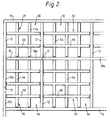
- the transverse runners 12 are additionally provided, at their ends, with downwardly directed hooks 30 on each side flange 16,18. These hooks are so positioned as to be engageable in the slits 24 of a main runner 10, thereby to define a main grid as illustrated in Figure 2.
- Figure 1A illustrates a splicing element 32 which has many similarities to the main and transverse runners 10,12, and is of a slightly smaller dimension so as to be insertable in the main runner.
- the splicing element is of channel cross-section having a web 34, and side flanges 36,38. Again, these side flanges are provided with slits 40, apertures 42, and recesses 44, located to align with the corresponding elements 24,26,28 in the main runner.
- the upper edges of the side flanges 36,38 are also provided with lugs 46.
- These splicing elements are used to connect, end to end, two main runners 10 to provide a more elongate structure.
- the lugs 46 can be engaged in opposite notches 23, in the rims 20,22 of the main runner. In fact, this will be done in notches adjacent the ends of each of the two main runners to be connected by a such a splicing element.
- the transverse runner 12 At the right-hand end of the transverse runner 12 as seen in Figure 1C, the transverse runner has been shown cut off at the desired modular location to suit the size of the grid opening to be formed in the ceiling which is desired.
- a clip element 50 In order to mount that end of the transverse runner on an adjacent main runner, a clip element 50, as seen in Figure 1G, is used. This again is of channel cross-section having a web 52, and side flanges 54,56, with upper lugs 58 on each of these side flanges.
- the clip element 50 At the right-hand end the clip element 50 is provided a hook 60 which is similar in configuration and location to the hook 30 on the end of the transverse runner 12. At the other end, and at a higher level, are further hooks 62, for a reason to be described shortly.
- transverse runners can be cut off at any modular location as illustrated, for example, by the line 63 to provide a shorter length of transverse runner.
- main runners 10 can be cut off at such locations, to suit a particular room size.
- FIGS 1D and 1E show first and second grid members 64,66 respectively. These are generally similar to one another and indeed are similar to the main and transverse runners 10,12 in their general structure. Thus, each consists of a lower web 67, and side flanges 68,70 provided with inturned rims 72, having notches 74.
- the first grid members 70 are of an underslung variety and have upper cut out 76, apertures 78 and short slits 80.
- the grid members 64,66 can be cut off at any modular location to a desired length, along cutting lines 83 which are conveniently at the location of the slits 80.
- the second grid members 66 have lower cut outs 82 adapted to inter-fit with the cut out 76 in a conventional way, projections 84 on the sides of the cut outs 82 being adapted lockingly to engage in the short slits 80.
- a clip 50 is inserted with the lugs 58 being engaged in adjacent notches 74.
- the hooks 62 at the left-hand end project outwardly of the first grid members 64 and are adapted to engage in recesses 28 in the main runners and/or in the transverse runners.
- the grid ceiling comprises three main runners 10, and three transverse runners 12, the transverse runners extending perpendicular to the main runners to define a number of differently shaped openings.
- Each of these openings have therein a grid element 91,93,95,97 respectively.
- the central main runner 10 is made up of two parts 10a,10b, joined at the point 11 by a splicing element (not shown in Figure 2) as shown in Figure 1A.
- the left-hand transverse runner 12 is made of two parts 12a,12b, joined at 13 in a similar way.
- the grid element 91 is made up of two first grid members 64, and two secondary members 66, each of identical length.
- the second grid element 93 is made up of three first grid members 64, and two second grid members 66, the latter being longer than the former.
- the third grid element 95 is made up of two first grid elements 64, and three second grid elements 66, these being shorter than the first grid members 64.
- the fourth grid element 97 is made up of three first grid members 64, and three second grid members 66, each of which is longer than the corresponding grid members 64,66 of the first grid element 91 thereby providing a square grid element which is larger than the grid element 91.
- runners and the grid elements can be adapted in their dimensions to suit a particular requirement of room dimension.
Landscapes
- Engineering & Computer Science (AREA)
- Architecture (AREA)
- Physics & Mathematics (AREA)
- Electromagnetism (AREA)
- Civil Engineering (AREA)
- Structural Engineering (AREA)
- Residential Or Office Buildings (AREA)
- Vehicle Interior And Exterior Ornaments, Soundproofing, And Insulation (AREA)
- Prostheses (AREA)
- Radiation-Therapy Devices (AREA)
- Specific Sealing Or Ventilating Devices For Doors And Windows (AREA)
Claims (6)
- Faux plafond à résille comprenant une pluralité de longerons principaux (10), s'étendant sensiblement parallèles les uns aux autres, une pluralité de longerons transversaux (12), s'étendant sensiblement parallèles les uns aux autres et perpendiculairement aux longerons principaux (10), afin de définir avec ceux-ci des ouvertures rectangulaires de résille, chacun desdits longerons étant de section transversale généralement en U, comportant une partie d'âme inférieure (14) reliant deux ailes latérales espacées (16, 18), formant les côtés verticaux des longerons principaux (10) et transversaux (12), les extrémités longitudinales des longerons transversaux (12) venant en butée contre les côtés verticaux des longerons principaux (10), des éléments de résille positionnés dans chacune desdites ouvertures de résille, chaque élément de résille comprenant une pluralité de premiers éléments de résille parallèles (64) et une pluralité de seconds éléments de résille parallèles (66) perpendiculaires aux premiers éléments de résille, des attaches généralement en U (50) engagées dans les extrémités desdits éléments de résille (64, 66), des premiers crochets (62) dépassant des extrémités desdites attaches (50), et des ouvertures ou évidements (28) dans lesdits longerons (10, 12) pouvant être saisis par lesdits premiers crochets desdites attaches (50) afin de maintenir les éléments de résille en place, un certain nombre au moins des éléments de résille (64, 66) étant adaptés pour être de longueur modifiée, comparés au reste desdits éléments de résille (64, 66), caractérisé en ce que les longerons principaux (10) et les longerons transversaux (12) sont de même dimension en coupe transversale que les premier et second éléments de résille (64, 66), en ce que d'autres desdites attaches (50) de forme généralement en U sont engagées dans les extrémités desdits longerons transversaux (12), des ouvertures ou évidements (24) sont formés dans lesdits longerons principaux (10), et des seconds crochets (60) desdites attaches (50) s'engagent dans lesdites ouvertures ou évidements pour maintenir les longerons transversaux (12) sur les longerons principaux (10) et en ce que les attaches (50) sont munies desdits premiers crochets (62) sur une première extrémité et desdits seconds crochets (60) sur l'autre extrémité.
- Faux plafond à résille selon la revendication 1, dans lequel les attaches (50) comportent à chaque extrémité une paire de crochets (60, 62), les crochets 62 à une première extrémité étant plus hauts que ceux (60) à l'autre extrémité, les crochets plus bas (60) étant les seconds crochets utilisés pour positionner les longerons transversaux (12) par rapport aux longerons principaux (10) et les crochets plus hauts (62) étant les premiers crochets agencés de manière à monter les éléments de résille sur les longerons (10, 12).
- Faux plafond à resille selon la revendication 1 ou 2, dans lequel les longerons en U (10, 12) comprennent des rebords tournés en dedans (20, 22) aux bords supérieurs des ailes (14, 18) et dans lequel des entailles espacées (23) sont formées dans lesdits rebords (20, 22).
- Faux plafond à résille selon la revendication 3 et comprenant en outre au moins un élément de raccordement (32) sous forme d'élément en U engagé dans l'un au moins desdits longerons (10, 12) à proximité immédiate de son extrémité et s'étendant au-delà de l'extrémité, lesdits éléments de raccordement (32) comportant des pattes (46) pouvant s engager dans les évidements (23) formés dans les rebords (20, 22), et dans lequel une seconde partie de longeron (10, 12) est engagée sur la partie libre dudit élément de raccordement (23) et est fixée aux longerons (10, 12) par celui-ci.
- Faux plafond à résille selon la revendication 3 ou 4, dans lequel l'élément d'attache (50) comprend une patte (58), sur chaque aile (54, 56) de l'élément d'attache (50), qui peut s'engager dans une paire opposée desdites entailles (23).
- Faux plafond à résille selon l'une quelconque des revendications précédentes, dans lequel l'un au moins desdits longerons principaux (10) et/ou dits longerons transversaux (12) a une aile (86) qui n'est pas munie d'ouvertures, d'évidements ou d'entailles.
Applications Claiming Priority (2)
| Application Number | Priority Date | Filing Date | Title |
|---|---|---|---|
| GB9019767 | 1990-09-10 | ||
| GB9019767A GB2247701A (en) | 1990-09-10 | 1990-09-10 | A grid ceiling system. |
Publications (2)
| Publication Number | Publication Date |
|---|---|
| EP0475721A1 EP0475721A1 (fr) | 1992-03-18 |
| EP0475721B1 true EP0475721B1 (fr) | 1994-12-14 |
Family
ID=10681969
Family Applications (1)
| Application Number | Title | Priority Date | Filing Date |
|---|---|---|---|
| EP91308241A Expired - Lifetime EP0475721B1 (fr) | 1990-09-10 | 1991-09-10 | Système de faux-plafonds à résille |
Country Status (5)
| Country | Link |
|---|---|
| EP (1) | EP0475721B1 (fr) |
| AT (1) | ATE115666T1 (fr) |
| DE (1) | DE69105886T2 (fr) |
| DK (1) | DK0475721T3 (fr) |
| GB (1) | GB2247701A (fr) |
Cited By (2)
| Publication number | Priority date | Publication date | Assignee | Title |
|---|---|---|---|---|
| KR20190024142A (ko) * | 2017-08-31 | 2019-03-08 | (주)유창 | 천장 마감재 체결을 위한 프레임 구조 |
| US10233639B2 (en) * | 2017-03-02 | 2019-03-19 | Usg Interiors, Llc | Open plenum utility channel |
Families Citing this family (7)
| Publication number | Priority date | Publication date | Assignee | Title |
|---|---|---|---|---|
| EP1741848A1 (fr) * | 2005-07-08 | 2007-01-10 | Tego System AB | Système de plafond fonctionnel et procédé de mise à la terre d'un tel système |
| NL2011556C2 (nl) | 2013-10-04 | 2015-04-09 | Saint Gobain Acoustical Products Internat B V | Plafondophangsysteem, profiel en werkwijze. |
| US9771718B1 (en) | 2016-10-07 | 2017-09-26 | Tate Access Floors Leasing, Inc. | Strut with non-structural infill |
| CN107386516B (zh) * | 2017-08-31 | 2023-06-16 | 广州康普顿至高建材有限公司 | 一种相交条形格栅及其安装方法 |
| CN113027002B (zh) * | 2021-01-28 | 2024-09-06 | 浙江亚厦装饰股份有限公司 | 一种模块式隔墙及其装配方法 |
| CN113502970B (zh) * | 2021-08-11 | 2022-07-26 | 苏州美瑞德建筑装饰有限公司 | 一种防止安装松动的可调式设计铝方通固定结构 |
| CN114319702A (zh) * | 2021-12-20 | 2022-04-12 | 浙江亚厦装饰股份有限公司 | 一种高度可调的格栅吊顶 |
Family Cites Families (5)
| Publication number | Priority date | Publication date | Assignee | Title |
|---|---|---|---|---|
| FR1505905A (fr) * | 1966-12-21 | 1967-12-15 | Paroi à armature | |
| CA1194666A (fr) * | 1983-06-08 | 1985-10-08 | Jack H.B. Hagman | Raccord |
| GB8509345D0 (en) * | 1985-04-11 | 1985-05-15 | Hunter Douglas Ind Bv | Grid ceiling |
| US4850172A (en) * | 1986-04-25 | 1989-07-25 | Alcan Aluminum Corporation | Ceiling or like structural system and splice member therefor |
| GB2232694A (en) * | 1989-04-19 | 1990-12-19 | Hunter Douglas Ind Bv | Grid ceiling with separate connectors |
-
1990
- 1990-09-10 GB GB9019767A patent/GB2247701A/en not_active Withdrawn
-
1991
- 1991-09-10 DK DK91308241.8T patent/DK0475721T3/da active
- 1991-09-10 AT AT91308241T patent/ATE115666T1/de not_active IP Right Cessation
- 1991-09-10 DE DE69105886T patent/DE69105886T2/de not_active Expired - Fee Related
- 1991-09-10 EP EP91308241A patent/EP0475721B1/fr not_active Expired - Lifetime
Cited By (2)
| Publication number | Priority date | Publication date | Assignee | Title |
|---|---|---|---|---|
| US10233639B2 (en) * | 2017-03-02 | 2019-03-19 | Usg Interiors, Llc | Open plenum utility channel |
| KR20190024142A (ko) * | 2017-08-31 | 2019-03-08 | (주)유창 | 천장 마감재 체결을 위한 프레임 구조 |
Also Published As
| Publication number | Publication date |
|---|---|
| GB9019767D0 (en) | 1990-10-24 |
| ATE115666T1 (de) | 1994-12-15 |
| EP0475721A1 (fr) | 1992-03-18 |
| DE69105886T2 (de) | 1995-05-04 |
| GB2247701A (en) | 1992-03-11 |
| DE69105886D1 (de) | 1995-01-26 |
| DK0475721T3 (da) | 1995-05-29 |
Similar Documents
| Publication | Publication Date | Title |
|---|---|---|
| US4047348A (en) | Ceiling support grid system | |
| US5768850A (en) | Method for erecting floor boards and a board assembly using the method | |
| EP0475721B1 (fr) | Système de faux-plafonds à résille | |
| US3675957A (en) | Locking connection for supporting grid systems | |
| EP0198982A2 (fr) | Faux plafond à résilles | |
| US5735221A (en) | Backroom shelving system | |
| US4499697A (en) | Suspended ceiling with removable tee sections | |
| US4699341A (en) | System for mounting radio equipment in vehicles | |
| US20240055843A1 (en) | Cable Tray Assembly | |
| EP0198141A2 (fr) | Plafond en treillis | |
| US6520345B1 (en) | Self-squaring relay rack assembly | |
| US4336673A (en) | Mosaic display panel | |
| FI71386B (fi) | Haengtakgallersystem | |
| US4598521A (en) | Suspension ceiling grid with end connector | |
| US3996716A (en) | Ceiling grid arrangement and connector used therewith | |
| US3949534A (en) | Interkeyed panel edge corner joint | |
| EP0047193A2 (fr) | Panneau d'affichage mosaique | |
| CA1267264A (fr) | Panneau pour faux-plafond a profiles suspendus | |
| GB2232694A (en) | Grid ceiling with separate connectors | |
| EP0266330A1 (fr) | Cadre pour la suspension de panneaux de plafond | |
| GB2274973A (en) | Suppport bar for shelving system | |
| JP3159511B2 (ja) | グレーチング | |
| EP1251611B1 (fr) | Structure de panneau de distribution électrique | |
| CA1317432C (fr) | Clip amovible | |
| CA1224317A (fr) | Plancher modulair a panneaux |
Legal Events
| Date | Code | Title | Description |
|---|---|---|---|
| PUAI | Public reference made under article 153(3) epc to a published international application that has entered the european phase |
Free format text: ORIGINAL CODE: 0009012 |
|
| AK | Designated contracting states |
Kind code of ref document: A1 Designated state(s): AT BE CH DE DK ES FR GB GR IT LI NL SE |
|
| 17P | Request for examination filed |
Effective date: 19920909 |
|
| 17Q | First examination report despatched |
Effective date: 19931118 |
|
| GRAA | (expected) grant |
Free format text: ORIGINAL CODE: 0009210 |
|
| AK | Designated contracting states |
Kind code of ref document: B1 Designated state(s): AT BE CH DE DK ES FR GB GR IT LI NL SE |
|
| PG25 | Lapsed in a contracting state [announced via postgrant information from national office to epo] |
Ref country code: GR Free format text: LAPSE BECAUSE OF FAILURE TO SUBMIT A TRANSLATION OF THE DESCRIPTION OR TO PAY THE FEE WITHIN THE PRESCRIBED TIME-LIMIT Effective date: 19941214 Ref country code: ES Free format text: THE PATENT HAS BEEN ANNULLED BY A DECISION OF A NATIONAL AUTHORITY Effective date: 19941214 Ref country code: AT Effective date: 19941214 |
|
| REF | Corresponds to: |
Ref document number: 115666 Country of ref document: AT Date of ref document: 19941215 Kind code of ref document: T |
|
| REF | Corresponds to: |
Ref document number: 69105886 Country of ref document: DE Date of ref document: 19950126 |
|
| ET | Fr: translation filed | ||
| ITF | It: translation for a ep patent filed | ||
| PG25 | Lapsed in a contracting state [announced via postgrant information from national office to epo] |
Ref country code: SE Effective date: 19950314 |
|
| REG | Reference to a national code |
Ref country code: DK Ref legal event code: T3 |
|
| PLBE | No opposition filed within time limit |
Free format text: ORIGINAL CODE: 0009261 |
|
| STAA | Information on the status of an ep patent application or granted ep patent |
Free format text: STATUS: NO OPPOSITION FILED WITHIN TIME LIMIT |
|
| 26N | No opposition filed | ||
| PGFP | Annual fee paid to national office [announced via postgrant information from national office to epo] |
Ref country code: DK Payment date: 19970912 Year of fee payment: 7 |
|
| PG25 | Lapsed in a contracting state [announced via postgrant information from national office to epo] |
Ref country code: DK Free format text: LAPSE BECAUSE OF NON-PAYMENT OF DUE FEES Effective date: 19980910 |
|
| PGFP | Annual fee paid to national office [announced via postgrant information from national office to epo] |
Ref country code: GB Payment date: 19990908 Year of fee payment: 9 |
|
| PGFP | Annual fee paid to national office [announced via postgrant information from national office to epo] |
Ref country code: FR Payment date: 19990909 Year of fee payment: 9 |
|
| PGFP | Annual fee paid to national office [announced via postgrant information from national office to epo] |
Ref country code: DE Payment date: 19990910 Year of fee payment: 9 |
|
| PGFP | Annual fee paid to national office [announced via postgrant information from national office to epo] |
Ref country code: CH Payment date: 19990913 Year of fee payment: 9 |
|
| PGFP | Annual fee paid to national office [announced via postgrant information from national office to epo] |
Ref country code: NL Payment date: 19990930 Year of fee payment: 9 |
|
| PGFP | Annual fee paid to national office [announced via postgrant information from national office to epo] |
Ref country code: BE Payment date: 19991119 Year of fee payment: 9 |
|
| REG | Reference to a national code |
Ref country code: DK Ref legal event code: EBP |
|
| PG25 | Lapsed in a contracting state [announced via postgrant information from national office to epo] |
Ref country code: GB Free format text: LAPSE BECAUSE OF NON-PAYMENT OF DUE FEES Effective date: 20000910 |
|
| PG25 | Lapsed in a contracting state [announced via postgrant information from national office to epo] |
Ref country code: LI Free format text: LAPSE BECAUSE OF NON-PAYMENT OF DUE FEES Effective date: 20000930 Ref country code: CH Free format text: LAPSE BECAUSE OF NON-PAYMENT OF DUE FEES Effective date: 20000930 Ref country code: BE Free format text: LAPSE BECAUSE OF NON-PAYMENT OF DUE FEES Effective date: 20000930 |
|
| BERE | Be: lapsed |
Owner name: HUNTER DOUGLAS INDUSTRIES B.V. Effective date: 20000930 |
|
| PG25 | Lapsed in a contracting state [announced via postgrant information from national office to epo] |
Ref country code: NL Free format text: LAPSE BECAUSE OF NON-PAYMENT OF DUE FEES Effective date: 20010401 |
|
| GBPC | Gb: european patent ceased through non-payment of renewal fee |
Effective date: 20000910 |
|
| REG | Reference to a national code |
Ref country code: CH Ref legal event code: PL |
|
| PG25 | Lapsed in a contracting state [announced via postgrant information from national office to epo] |
Ref country code: FR Free format text: LAPSE BECAUSE OF NON-PAYMENT OF DUE FEES Effective date: 20010531 |
|
| NLV4 | Nl: lapsed or anulled due to non-payment of the annual fee |
Effective date: 20010401 |
|
| PG25 | Lapsed in a contracting state [announced via postgrant information from national office to epo] |
Ref country code: DE Free format text: LAPSE BECAUSE OF NON-PAYMENT OF DUE FEES Effective date: 20010601 |
|
| REG | Reference to a national code |
Ref country code: FR Ref legal event code: ST |
|
| PG25 | Lapsed in a contracting state [announced via postgrant information from national office to epo] |
Ref country code: IT Free format text: LAPSE BECAUSE OF NON-PAYMENT OF DUE FEES;WARNING: LAPSES OF ITALIAN PATENTS WITH EFFECTIVE DATE BEFORE 2007 MAY HAVE OCCURRED AT ANY TIME BEFORE 2007. THE CORRECT EFFECTIVE DATE MAY BE DIFFERENT FROM THE ONE RECORDED. Effective date: 20050910 |