EP0475743A1 - Régulateur d'infusion compensé par pression - Google Patents
Régulateur d'infusion compensé par pression Download PDFInfo
- Publication number
- EP0475743A1 EP0475743A1 EP19910308302 EP91308302A EP0475743A1 EP 0475743 A1 EP0475743 A1 EP 0475743A1 EP 19910308302 EP19910308302 EP 19910308302 EP 91308302 A EP91308302 A EP 91308302A EP 0475743 A1 EP0475743 A1 EP 0475743A1
- Authority
- EP
- European Patent Office
- Prior art keywords
- infusion
- infusion regulator
- diaphragm
- valve
- housing part
- Prior art date
- Legal status (The legal status is an assumption and is not a legal conclusion. Google has not performed a legal analysis and makes no representation as to the accuracy of the status listed.)
- Ceased
Links
- 238000001802 infusion Methods 0.000 title claims abstract description 32
- 230000000717 retained effect Effects 0.000 claims abstract description 10
- 230000000694 effects Effects 0.000 claims abstract description 8
- 230000002093 peripheral effect Effects 0.000 claims abstract description 8
- 239000007788 liquid Substances 0.000 claims abstract description 5
- 239000003978 infusion fluid Substances 0.000 claims description 8
- CBVWMGCJNPPAAR-HJWRWDBZSA-N (nz)-n-(5-methylheptan-3-ylidene)hydroxylamine Chemical compound CCC(C)C\C(CC)=N/O CBVWMGCJNPPAAR-HJWRWDBZSA-N 0.000 claims description 2
- ZZUFCTLCJUWOSV-UHFFFAOYSA-N furosemide Chemical group C1=C(Cl)C(S(=O)(=O)N)=CC(C(O)=O)=C1NCC1=CC=CO1 ZZUFCTLCJUWOSV-UHFFFAOYSA-N 0.000 claims description 2
- 238000009877 rendering Methods 0.000 claims description 2
- 210000004894 snout Anatomy 0.000 claims description 2
- 238000011144 upstream manufacturing Methods 0.000 claims description 2
- 238000006073 displacement reaction Methods 0.000 claims 1
- 210000003128 head Anatomy 0.000 description 2
- 230000001447 compensatory effect Effects 0.000 description 1
- 238000001914 filtration Methods 0.000 description 1
- 239000000463 material Substances 0.000 description 1
- 238000012544 monitoring process Methods 0.000 description 1
- 230000037452 priming Effects 0.000 description 1
- 230000000630 rising effect Effects 0.000 description 1
- 230000000007 visual effect Effects 0.000 description 1
Images

Classifications
-
- A—HUMAN NECESSITIES
- A61—MEDICAL OR VETERINARY SCIENCE; HYGIENE
- A61M—DEVICES FOR INTRODUCING MEDIA INTO, OR ONTO, THE BODY; DEVICES FOR TRANSDUCING BODY MEDIA OR FOR TAKING MEDIA FROM THE BODY; DEVICES FOR PRODUCING OR ENDING SLEEP OR STUPOR
- A61M5/00—Devices for bringing media into the body in a subcutaneous, intra-vascular or intramuscular way; Accessories therefor, e.g. filling or cleaning devices, arm-rests
- A61M5/14—Infusion devices, e.g. infusing by gravity; Blood infusion; Accessories therefor
- A61M5/168—Means for controlling media flow to the body or for metering media to the body, e.g. drip meters, counters ; Monitoring media flow to the body
- A61M5/16877—Adjusting flow; Devices for setting a flow rate
- A61M5/16881—Regulating valves
-
- G—PHYSICS
- G05—CONTROLLING; REGULATING
- G05D—SYSTEMS FOR CONTROLLING OR REGULATING NON-ELECTRIC VARIABLES
- G05D7/00—Control of flow
- G05D7/01—Control of flow without auxiliary power
- G05D7/0106—Control of flow without auxiliary power the sensing element being a flexible member, e.g. bellows, diaphragm, capsule
-
- Y—GENERAL TAGGING OF NEW TECHNOLOGICAL DEVELOPMENTS; GENERAL TAGGING OF CROSS-SECTIONAL TECHNOLOGIES SPANNING OVER SEVERAL SECTIONS OF THE IPC; TECHNICAL SUBJECTS COVERED BY FORMER USPC CROSS-REFERENCE ART COLLECTIONS [XRACs] AND DIGESTS
- Y10—TECHNICAL SUBJECTS COVERED BY FORMER USPC
- Y10T—TECHNICAL SUBJECTS COVERED BY FORMER US CLASSIFICATION
- Y10T137/00—Fluid handling
- Y10T137/7722—Line condition change responsive valves
- Y10T137/7781—With separate connected fluid reactor surface
- Y10T137/7784—Responsive to change in rate of fluid flow
- Y10T137/7787—Expansible chamber subject to differential pressures
- Y10T137/7788—Pressures across fixed choke
Definitions
- the present invention relates to a pressure-compensated infusion regulator, and in particular to an adjustable-rate, dual-diaphragm pressure-compensated infusion regulator.
- U.S. Patent 4,796,660 discloses an infusion set in which a degree of output constancy was achieved by flow regulation at the inlet part of the regulator rather than at the outlet part as was common usage previously (see, for instance, U.S. Patent 4,343,305). This was done by providing, in the high-pressure part of the regulator, a valve linked to, and following the movements of, the regulator diaphragm, and a valve seat fixedly located below the head of that valve. The infusion liquid passed through, and was throttled by, the annular gap between seat and head, which gap varied as a function of the pressure drop across the diaphragm.
- a dual-diaphragm, adjustable rate, pressure-compensated infusion regulator comprising an inverted-cup-shaped, first housing part having substantially cylindrical walls and a downward-facing bottom surface with an inlet port, said first housing part being provided with an inlet connector connectable to a relatively high-pressure infusion-liquid source; a second housing part attachable to said first housing part and having an outlet port; an intermediate member comprised at least of an annular portion interposed between and rotatable relative to either of said first and said second housing parts, and having means rendering it stationary relative to the other one of said housing parts; a flexible main diaphragm retained along a peripheral portion thereof in said intermediate member and defining with its upper surface an inlet chamber and with its lower surface, an outlet chamber; a flow-regulating valve comprised of a valve head accessible to said high-pressure source and a valve stem one end of which is attached to said valve head; a flow-attenuating element of adjustable attenuating effect disposed in the path of
- FIG. 1 an in-line infusion regulator comprising a first housing part in the shape of an inverted cup of substantially cylindrical walls and a downward-facing bottom surface 4 with an inlet port 6.
- An inlet connector 8 permits connection to tubing.
- a second housing part 10 snap-fits with its peripheral rim 12 into a groove 14 in the first housing part 2 and, with respect to the latter, has thus one degree of freedom in rotation. Relative mutual rotation of the two housing parts 2 and 10 (for a purpose to be discussed further below) is facilitated by a plurality of ribs 16 on the outer surface of the first housing part 2 on one hand, and two wing-like projections 18 integral with the second housing part 10, on the other. The latter is also provided with an outlet port 20 and an outlet connector 22.
- the intermediate member 26 which, due to a number of lugs 28 engaging, in assembly, a corresponding number of appropriately shaped recesses 30 in the second housing part 10, can only rotate together with the latter.
- a bore 32 in the lower part of the member 26 is aligned with the outlet port 20 of the second housing member 10.
- an inward-projecting peripheral rim 34 on which is freely seated the flexible, elastically-deformable main diaphragm 36, centered by means of a plurality of ribs 38.
- the diaphragm 36 defines, with its upper surface, an inlet chamber 40 and with its lower surface, an outlet chamber 42.
- valve-controlling pad 47 attached to, or integral with, a valve stem 48 that carries the valve head 50.
- valve seat 52 which, together with the valve head 50, defines a gap through which the infusion liquid can reach the inlet chamber 40.
- Fig. 1 is similar to the design of the infusion regulator shown in Fig. 7 of the above-mentioned U.S. Patent 4,796,660, which also explains in detail the manner in which the constant-output (i.e., flow-regulation) feature operates, while the adjustable-rate feature is exhaustively explained in U.S. Patent 4,343,305.
- constant-output i.e., flow-regulation
- the advantage of the present infusion regulator resides in the manner in which it solves the above-mentioned problem of output decay at relatively high pressures, when the diaphragm, as mentioned earlier, is liable to overreact, i.e., to bulge to a degree that, in the infusion set of U.S. Patent 4,796,660, would cause the valve head to throttle the flow of infusion fluid almost to zero.
- the valve seat 52 is not a hole in a rigid portion of the first housing part 2, but in a flexible, discoid auxiliary diaphragm 54 retained in housing part 2 by means of a sleeve 56 and exposed to the high pressure of the infusion liquid source, which pressure, when rising, deflects the auxiliary diaphragm 54.
- a sleeve 56 and exposed to the high pressure of the infusion liquid source, which pressure, when rising, deflects the auxiliary diaphragm 54.
- a circular, knife-edge-like rim 58 projecting from the bottom surface 4 of the first housing part 2, which about touches the main diaphragm 36 in the relaxed state thereof.
- the rim 58 constitutes the seat of the main diaphram when serving, as it does, as non-return valve.
- flow-attenuating groove 44 could also be provided in the bottom surface 4 of the first housing part 2 rather than in the intermediate member 26, as indicated by the dashed groove 44′.
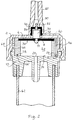
- Fig. 2 differs in several details from that of Fig. 1.
- a pointed snout 60 adapted to be pushed into the infusion bag.
- a transparent drip chamber 62 permitting visual monitoring of the functioning of the regulator.
- the intermediate member 26 is annular rather than cup-shaped and the flow-attenuating groove 44 is provided in the lower edge of the member 26. It could also be located on the surface 24 of the second housing part 10, as indicated by the dashed groove 44′.
- intermediate member 26 Due to the location of the groove 44 at the interface: intermediate member 26/second housing part 10, the intermediate member 26 must obviously be stationary relative to the first housing part 2. This is achieved by providing slots 66 on the periphery of the intermediate member 26, in which engage ribs 68 of appropriate size and spacing.
- a linking rod 70 firmly connects the valve stem 48 and valve head 50 to the main diaphragm 36, by means of a barb fastener 71, and the auxiliary diaphragm 54 is now in the shape of an inverted cup having a beaded edge 72 retained in an undercut in the cylindrical bore constituting the inlet port 6.
- Fig. 2 has no use for a non-return valve because of the need, during the priming stage of the regulator, to release air upwardly.
Landscapes
- Health & Medical Sciences (AREA)
- Physics & Mathematics (AREA)
- Engineering & Computer Science (AREA)
- Biomedical Technology (AREA)
- Hematology (AREA)
- Automation & Control Theory (AREA)
- Vascular Medicine (AREA)
- Anesthesiology (AREA)
- General Physics & Mathematics (AREA)
- Heart & Thoracic Surgery (AREA)
- Fluid Mechanics (AREA)
- Life Sciences & Earth Sciences (AREA)
- Animal Behavior & Ethology (AREA)
- General Health & Medical Sciences (AREA)
- Public Health (AREA)
- Veterinary Medicine (AREA)
- Infusion, Injection, And Reservoir Apparatuses (AREA)
Applications Claiming Priority (2)
| Application Number | Priority Date | Filing Date | Title |
|---|---|---|---|
| IL95660 | 1990-09-12 | ||
| IL9566090A IL95660A (en) | 1990-09-12 | 1990-09-12 | Pressure-compensated infusion regulator |
Publications (1)
| Publication Number | Publication Date |
|---|---|
| EP0475743A1 true EP0475743A1 (fr) | 1992-03-18 |
Family
ID=11061577
Family Applications (1)
| Application Number | Title | Priority Date | Filing Date |
|---|---|---|---|
| EP19910308302 Ceased EP0475743A1 (fr) | 1990-09-12 | 1991-09-11 | Régulateur d'infusion compensé par pression |
Country Status (3)
| Country | Link |
|---|---|
| US (1) | US5137522A (fr) |
| EP (1) | EP0475743A1 (fr) |
| IL (1) | IL95660A (fr) |
Cited By (11)
| Publication number | Priority date | Publication date | Assignee | Title |
|---|---|---|---|---|
| WO2000016177A1 (fr) * | 1998-09-17 | 2000-03-23 | Global Agricultural Technology And Engineering, Llc | Vanne de regulation de pression |
| EP1099456A1 (fr) * | 1999-11-12 | 2001-05-16 | Industrie Borla SpA | Clapet antiretour pour des lignes de perfusion et similaires |
| EP1233798A4 (fr) * | 1999-11-18 | 2003-05-07 | Medrip Ltd | Regulateur de debit reagissant a la pression et dispositifs de liberation de medicaments utilisant ce regulateur |
| WO2004064904A1 (fr) * | 2003-01-20 | 2004-08-05 | Olaf Franksson | Système de perfusion |
| WO2004078238A1 (fr) * | 2003-02-28 | 2004-09-16 | Baxter International Inc. | Regulateur de pression pour un dispositif a perfusion |
| US6881005B2 (en) | 2001-11-09 | 2005-04-19 | Saul Siney Sosa | Frame connection mechanism |
| EP1745812A1 (fr) * | 2005-07-22 | 2007-01-24 | RoweMed AG - Medical 4 Life | Soupape pour un fluide, en particulier pour être appliquée dans une pompe pour des liquides actuée méchanicalement |
| US7363938B1 (en) | 2005-03-22 | 2008-04-29 | Global Agricultural Technology And Engineering, Llc | Constant flow valve assembly |
| US7445021B2 (en) | 2005-03-22 | 2008-11-04 | Global Agricultural Technology And Engineering, Llc | Constant flow valve |
| US7814931B2 (en) | 2006-07-12 | 2010-10-19 | Global Agricultural Technology And Engineering, Llc | Selectively actuated constant flow valve |
| US8240522B2 (en) | 2007-10-16 | 2012-08-14 | Global Agricultural Technology & Engineering Llc | Dual function dispensing head for carbonated beverage machine |
Families Citing this family (11)
| Publication number | Priority date | Publication date | Assignee | Title |
|---|---|---|---|---|
| US5222948A (en) * | 1991-09-09 | 1993-06-29 | Path | Injection port for single-use syringe |
| US5401255A (en) * | 1993-07-20 | 1995-03-28 | Baxter International Inc. | Multi-functional valve with unitary valving member and improved safety |
| US5634594A (en) * | 1993-07-30 | 1997-06-03 | Cohen; Amir | Flow control device particularly useful in drip irrigation emitters |
| US5514102A (en) * | 1995-05-05 | 1996-05-07 | Zevex Incorporated | Pressure monitoring enteral feeding system and method |
| US5749854A (en) * | 1996-06-11 | 1998-05-12 | Shen; Chung-Shan | Pneumatic controlled infusion device |
| US6053896A (en) * | 1998-05-01 | 2000-04-25 | Cobe Cardiovascular Operating Co., Inc. | Left ventricle valve |
| US20050075612A1 (en) * | 2003-10-03 | 2005-04-07 | Baxter International Inc. | Parylene coated fluid flow regulator |
| US20070221273A1 (en) * | 2006-03-22 | 2007-09-27 | Landers Jerry L | Valve for beverage dispenser |
| CN103269731B (zh) | 2010-10-01 | 2015-11-25 | 泽维克斯公司 | 用于基于管材料性能来提高蠕动泵系统的精确度的方法 |
| US8905064B2 (en) * | 2011-10-03 | 2014-12-09 | Seik Oh | Flow regulator for infusion pump and method of manufacturing the same |
| DE102019104728A1 (de) * | 2019-02-25 | 2020-08-27 | Nidec Gpm Gmbh | Pumpeinheit aufweisend einen Steckverbinder mit Druckausgleichselement |
Citations (4)
| Publication number | Priority date | Publication date | Assignee | Title |
|---|---|---|---|---|
| US3782858A (en) * | 1972-10-24 | 1974-01-01 | Red Jacket Mfg Co | Control apparatus for a water supply system |
| US4343305A (en) * | 1977-10-14 | 1982-08-10 | Dan Bron | Adjustable-rate, constant output infusion set |
| US4796660A (en) * | 1986-03-05 | 1989-01-10 | Manisa Establishment | Drip emitter |
| US4867198A (en) * | 1988-10-11 | 1989-09-19 | Faust Bobby G | Adjustable flow regulating valve |
Family Cites Families (4)
| Publication number | Priority date | Publication date | Assignee | Title |
|---|---|---|---|---|
| US4000740A (en) * | 1974-05-31 | 1977-01-04 | Baxter Travenol Laboratories, Inc. | Injection site |
| US4904236A (en) * | 1987-01-30 | 1990-02-27 | Vir Engineering | Fluid flow control valve |
| US5009391A (en) * | 1988-05-02 | 1991-04-23 | The Kendall Company | Valve assembly |
| US5070905A (en) * | 1990-05-29 | 1991-12-10 | Joseph Paradis | Directional flow control |
-
1990
- 1990-09-12 IL IL9566090A patent/IL95660A/en not_active IP Right Cessation
-
1991
- 1991-09-06 US US07/755,806 patent/US5137522A/en not_active Expired - Fee Related
- 1991-09-11 EP EP19910308302 patent/EP0475743A1/fr not_active Ceased
Patent Citations (4)
| Publication number | Priority date | Publication date | Assignee | Title |
|---|---|---|---|---|
| US3782858A (en) * | 1972-10-24 | 1974-01-01 | Red Jacket Mfg Co | Control apparatus for a water supply system |
| US4343305A (en) * | 1977-10-14 | 1982-08-10 | Dan Bron | Adjustable-rate, constant output infusion set |
| US4796660A (en) * | 1986-03-05 | 1989-01-10 | Manisa Establishment | Drip emitter |
| US4867198A (en) * | 1988-10-11 | 1989-09-19 | Faust Bobby G | Adjustable flow regulating valve |
Cited By (13)
| Publication number | Priority date | Publication date | Assignee | Title |
|---|---|---|---|---|
| WO2000016177A1 (fr) * | 1998-09-17 | 2000-03-23 | Global Agricultural Technology And Engineering, Llc | Vanne de regulation de pression |
| EP1099456A1 (fr) * | 1999-11-12 | 2001-05-16 | Industrie Borla SpA | Clapet antiretour pour des lignes de perfusion et similaires |
| EP1233798A4 (fr) * | 1999-11-18 | 2003-05-07 | Medrip Ltd | Regulateur de debit reagissant a la pression et dispositifs de liberation de medicaments utilisant ce regulateur |
| US6881005B2 (en) | 2001-11-09 | 2005-04-19 | Saul Siney Sosa | Frame connection mechanism |
| WO2004064904A1 (fr) * | 2003-01-20 | 2004-08-05 | Olaf Franksson | Système de perfusion |
| WO2004078238A1 (fr) * | 2003-02-28 | 2004-09-16 | Baxter International Inc. | Regulateur de pression pour un dispositif a perfusion |
| US7445021B2 (en) | 2005-03-22 | 2008-11-04 | Global Agricultural Technology And Engineering, Llc | Constant flow valve |
| US7363938B1 (en) | 2005-03-22 | 2008-04-29 | Global Agricultural Technology And Engineering, Llc | Constant flow valve assembly |
| US7617839B2 (en) | 2005-03-22 | 2009-11-17 | Global Agricultural Technology And Engineering, Llc | Constant flow valve |
| WO2007009808A1 (fr) * | 2005-07-22 | 2007-01-25 | Rowemed Ag - Medical 4 Life | Soupape destinee a un fluide, destinee en particulier a etre utilisee dans une pompe a liquide a fonctionnement mecanique |
| EP1745812A1 (fr) * | 2005-07-22 | 2007-01-24 | RoweMed AG - Medical 4 Life | Soupape pour un fluide, en particulier pour être appliquée dans une pompe pour des liquides actuée méchanicalement |
| US7814931B2 (en) | 2006-07-12 | 2010-10-19 | Global Agricultural Technology And Engineering, Llc | Selectively actuated constant flow valve |
| US8240522B2 (en) | 2007-10-16 | 2012-08-14 | Global Agricultural Technology & Engineering Llc | Dual function dispensing head for carbonated beverage machine |
Also Published As
| Publication number | Publication date |
|---|---|
| US5137522A (en) | 1992-08-11 |
| IL95660A0 (en) | 1991-06-30 |
| IL95660A (en) | 1994-02-27 |
Similar Documents
| Publication | Publication Date | Title |
|---|---|---|
| US5137522A (en) | Pressure-compensated infusion regulator | |
| US4998556A (en) | Drip emitter | |
| US5101854A (en) | Low-output flow regulator | |
| CA1176933A (fr) | Pompe a sang dotee d'un diaphragme | |
| US7114520B2 (en) | Pressure regulator | |
| EP0247824B2 (fr) | Valve pour système d'infusion de substances médicamenteuses | |
| EP0142558B1 (fr) | Regulateur d'ecoulement intraveineux | |
| US5725017A (en) | In-line pressure check valve for drug-delivery systems | |
| US4381005A (en) | Intravenous pump chamber | |
| AU2002329852A1 (en) | Pressure regulator | |
| US4925451A (en) | I.V. flow control device | |
| JPH0747044B2 (ja) | 重力式点滴および輸血用流量調整装置 | |
| WO2004078238A1 (fr) | Regulateur de pression pour un dispositif a perfusion | |
| US6164321A (en) | Liquid flow regulator for use in infusion sets | |
| HK1066286B (en) | Pressure regulator |
Legal Events
| Date | Code | Title | Description |
|---|---|---|---|
| PUAI | Public reference made under article 153(3) epc to a published international application that has entered the european phase |
Free format text: ORIGINAL CODE: 0009012 |
|
| AK | Designated contracting states |
Kind code of ref document: A1 Designated state(s): AT CH DE FR GB IT LI SE |
|
| 17P | Request for examination filed |
Effective date: 19920820 |
|
| 17Q | First examination report despatched |
Effective date: 19941020 |
|
| STAA | Information on the status of an ep patent application or granted ep patent |
Free format text: STATUS: THE APPLICATION HAS BEEN REFUSED |
|
| 18R | Application refused |
Effective date: 19950408 |