EP0475792A1 - Verfahren zur Herstellung eines Wälzlagerflansches und Wälzlager mit einem solchen Flansch - Google Patents
Verfahren zur Herstellung eines Wälzlagerflansches und Wälzlager mit einem solchen Flansch Download PDFInfo
- Publication number
- EP0475792A1 EP0475792A1 EP91402103A EP91402103A EP0475792A1 EP 0475792 A1 EP0475792 A1 EP 0475792A1 EP 91402103 A EP91402103 A EP 91402103A EP 91402103 A EP91402103 A EP 91402103A EP 0475792 A1 EP0475792 A1 EP 0475792A1
- Authority
- EP
- European Patent Office
- Prior art keywords
- flange
- ring
- bearing assembly
- bearing
- collar
- Prior art date
- Legal status (The legal status is an assumption and is not a legal conclusion. Google has not performed a legal analysis and makes no representation as to the accuracy of the status listed.)
- Granted
Links
Images

Classifications
-
- F—MECHANICAL ENGINEERING; LIGHTING; HEATING; WEAPONS; BLASTING
- F16—ENGINEERING ELEMENTS AND UNITS; GENERAL MEASURES FOR PRODUCING AND MAINTAINING EFFECTIVE FUNCTIONING OF MACHINES OR INSTALLATIONS; THERMAL INSULATION IN GENERAL
- F16C—SHAFTS; FLEXIBLE SHAFTS; ELEMENTS OR CRANKSHAFT MECHANISMS; ROTARY BODIES OTHER THAN GEARING ELEMENTS; BEARINGS
- F16C19/00—Bearings with rolling contact, for exclusively rotary movement
- F16C19/02—Bearings with rolling contact, for exclusively rotary movement with bearing balls essentially of the same size in one or more circular rows
- F16C19/14—Bearings with rolling contact, for exclusively rotary movement with bearing balls essentially of the same size in one or more circular rows for both radial and axial load
- F16C19/18—Bearings with rolling contact, for exclusively rotary movement with bearing balls essentially of the same size in one or more circular rows for both radial and axial load with two or more rows of balls
- F16C19/181—Bearings with rolling contact, for exclusively rotary movement with bearing balls essentially of the same size in one or more circular rows for both radial and axial load with two or more rows of balls with angular contact
- F16C19/183—Bearings with rolling contact, for exclusively rotary movement with bearing balls essentially of the same size in one or more circular rows for both radial and axial load with two or more rows of balls with angular contact with two rows at opposite angles
- F16C19/184—Bearings with rolling contact, for exclusively rotary movement with bearing balls essentially of the same size in one or more circular rows for both radial and axial load with two or more rows of balls with angular contact with two rows at opposite angles in O-arrangement
- F16C19/187—Bearings with rolling contact, for exclusively rotary movement with bearing balls essentially of the same size in one or more circular rows for both radial and axial load with two or more rows of balls with angular contact with two rows at opposite angles in O-arrangement with all four raceways integrated on parts other than race rings, e.g. fourth generation hubs
-
- F—MECHANICAL ENGINEERING; LIGHTING; HEATING; WEAPONS; BLASTING
- F16—ENGINEERING ELEMENTS AND UNITS; GENERAL MEASURES FOR PRODUCING AND MAINTAINING EFFECTIVE FUNCTIONING OF MACHINES OR INSTALLATIONS; THERMAL INSULATION IN GENERAL
- F16C—SHAFTS; FLEXIBLE SHAFTS; ELEMENTS OR CRANKSHAFT MECHANISMS; ROTARY BODIES OTHER THAN GEARING ELEMENTS; BEARINGS
- F16C35/00—Rigid support of bearing units; Housings, e.g. caps, covers
- F16C35/04—Rigid support of bearing units; Housings, e.g. caps, covers in the case of ball or roller bearings
- F16C35/06—Mounting or dismounting of ball or roller bearings; Fixing them onto shaft or in housing
- F16C35/063—Fixing them on the shaft
-
- F—MECHANICAL ENGINEERING; LIGHTING; HEATING; WEAPONS; BLASTING
- F16—ENGINEERING ELEMENTS AND UNITS; GENERAL MEASURES FOR PRODUCING AND MAINTAINING EFFECTIVE FUNCTIONING OF MACHINES OR INSTALLATIONS; THERMAL INSULATION IN GENERAL
- F16C—SHAFTS; FLEXIBLE SHAFTS; ELEMENTS OR CRANKSHAFT MECHANISMS; ROTARY BODIES OTHER THAN GEARING ELEMENTS; BEARINGS
- F16C43/00—Assembling bearings
- F16C43/04—Assembling rolling-contact bearings
-
- F—MECHANICAL ENGINEERING; LIGHTING; HEATING; WEAPONS; BLASTING
- F16—ENGINEERING ELEMENTS AND UNITS; GENERAL MEASURES FOR PRODUCING AND MAINTAINING EFFECTIVE FUNCTIONING OF MACHINES OR INSTALLATIONS; THERMAL INSULATION IN GENERAL
- F16C—SHAFTS; FLEXIBLE SHAFTS; ELEMENTS OR CRANKSHAFT MECHANISMS; ROTARY BODIES OTHER THAN GEARING ELEMENTS; BEARINGS
- F16C2326/00—Articles relating to transporting
- F16C2326/01—Parts of vehicles in general
- F16C2326/02—Wheel hubs or castors
Definitions
- the invention relates to a bearing assembly carrying an axial retention flange of an inner ring of a bearing with two rows of rolling bodies.
- the publication FR-A-2605557 describes a bearing assembly carrying a flange shaped by a pressing or forging tool driven by an oscillating movement around the axis of the bearing so as to radially flare the tubular end of a hub or ring during rotation.
- the thrust forces exerted directly or indirectly on the flange generate forces capable of causing the rupture of the flange and the axial ejection of the inner ring.
- the subject of the invention is a bearing assembly with a flange of the predefined type formed at the axial end of a bearing ring or of a hub, by pressing or forging by locating a bending zone of suitable size adjacent to a heat treated area in the direction of a local increase in the hardness of the bearing part of the collar.
- the invention also relates to a method for producing a flange, for example in contact with a member for axial tensioning of the bearing ring in order to achieve preload of the bearing assembly.
- the invention more particularly finds application in bearing assemblies which have at least one fixing flange.
- the internal face of the collar extends axially under the inner ring element by an axial support edge produced during the shaping process of the collar.
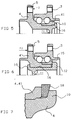
- FIG. 1 shows an axial half-section of an exemplary embodiment of the assembly. bearing with two fixing flanges.
- Figure 2 is a representation on a larger scale of the retaining flange of a ring element.
- Figures 3 and 4 are detailed representations of the flange showing its form of blank according to two alternative embodiments.
- Figure 5 shows in axial half-section an embodiment of the bearing assembly in which the flange is located on the inner ring.
- Figure 6 shows in axial half-section an embodiment of the bearing assembly in which the flange is located on a support of the inner ring.
- Figure 7 is a detailed representation of the flange in contact with a bearing preloading ring.
- the outer ring 1 of the bearing with two rows of rolling bodies 2 has a fixing flange 3 and two inner bearing tracks.
- An inner ring element 4 also has a fixing flange 5 and is mounted on another inner ring element 6.
- the axial end of the inner ring element 6 has a flange 10 made from a blank 10 ′ whose primitive sections shown in phantom in Figures 3 and 4, allow the realization on the flange of a functional bearing area of a transmission joint part.
- Figure 2 relates to the axial retaining means of an inner ring member such as 4 shown in Figure 1 or 6 or an inner ring member such as 41 shown in Figure 5.
- the face internal of the flange 10 is extended axially under the ring element 4 or 41 which has a reamed part with a lateral end of increased internal diameter in order to promote the nesting of the material constituting the flange 10 in contact with the element of the ring 4 or 41 during the implementation of the flange shaping process and the constitution on the ring element 6 of an axial support edge 11.
- the flange 10 and in particular its support zone are located substantially in the radial plane of the fixing flange 5 which radially extends the element 4 of the inner ring.
- FIG. 6 according to which the flange 10 is carried by an assembly sleeve 12 bearing on a ring element 15 on the element 4 for the purpose of dissociating the two rolling tracks from the rows of bodies rolling.
- the corresponding end of the elements 6, 4 or 12 is dimensioned accordingly in its thickness as shown in Figures 3 and 4. It is also possible to facilitate the shaping of the flange such as 10 by subjecting for example to the inner ring element 6 an appropriate heat treatment for hardening in a bearing zone 16 which supports the other element 4, 41 of the inner ring and which axially extends the axial bearing edge of the flange 10.
- the collar 10 is carried by a non-rotating and localized element outside the contact line of the rolling bodies and at a distance L from the bearing surface 16 under load (fig. 2).
- the elastic elongation of the ring element 4 (fig. 5) or of the bush 12 (fig. 6) is carried out. by applying opposing forces F1, F2 which put in elastic tension the rolling element before the application of the flange shaping tool.
- the elongation of the element 4 or 12 carrying the collar is carried out by heating it between 200 to 300 °.
- a ring 18 of appropriate section is used on the ring element 4 or 41 which is attached to the collar 10.
- the ring 18 is heated to a temperature between 200 and 300 ° C and mounted on the rolling element 4 or 12 before shaping the flange.
- the heating of the ring 18 can be carried out during the shaping of the collar.
- During the cooling of the ring its diameter decreases.
- the constriction of the ring creates an axial load on the bearing, the importance of which can be adjusted by following the control of the expansion of the ring.
Landscapes
- Engineering & Computer Science (AREA)
- General Engineering & Computer Science (AREA)
- Mechanical Engineering (AREA)
- Rolling Contact Bearings (AREA)
- Mounting Of Bearings Or Others (AREA)
Applications Claiming Priority (2)
| Application Number | Priority Date | Filing Date | Title |
|---|---|---|---|
| FR9010961 | 1990-09-04 | ||
| FR9010961A FR2666389B1 (fr) | 1990-09-04 | 1990-09-04 | Procede pour realiser une collerette de roulement et ensemble de roulement equipe d'une telle collerette. |
Publications (2)
| Publication Number | Publication Date |
|---|---|
| EP0475792A1 true EP0475792A1 (de) | 1992-03-18 |
| EP0475792B1 EP0475792B1 (de) | 1995-02-15 |
Family
ID=9400045
Family Applications (1)
| Application Number | Title | Priority Date | Filing Date |
|---|---|---|---|
| EP91402103A Expired - Lifetime EP0475792B1 (de) | 1990-09-04 | 1991-07-26 | Verfahren zur Herstellung eines Wälzlagerflansches und Wälzlager mit einem solchen Flansch |
Country Status (5)
| Country | Link |
|---|---|
| US (1) | US5226738A (de) |
| EP (1) | EP0475792B1 (de) |
| DE (1) | DE69107381T2 (de) |
| ES (1) | ES2067890T3 (de) |
| FR (1) | FR2666389B1 (de) |
Cited By (10)
| Publication number | Priority date | Publication date | Assignee | Title |
|---|---|---|---|---|
| DE4339847C1 (de) * | 1993-11-23 | 1995-06-01 | Kugelfischer G Schaefer & Co | Lagereinheit |
| EP0561377B1 (de) * | 1992-03-20 | 1997-07-16 | Skf Industrie S.P.A. | Wälzlager, insbesondere für ein Fahrzeugrad |
| EP0736398A3 (de) * | 1995-04-06 | 1997-10-29 | Skf Ind Spa | Kugellager für Nabe eines Kraftfahrzeugrades |
| DE19713211C2 (de) * | 1996-05-27 | 2001-10-04 | Koyo Seiko Co | Lagervorrichtung für eine Achse |
| FR2811613A1 (fr) | 2000-07-13 | 2002-01-18 | Roulements Soc Nouvelle | Palier a roulement, notamment pour roues non motrices de vehicule automobile |
| EP1172233A3 (de) * | 2000-07-10 | 2005-12-21 | Koyo Seiko Co., Ltd. | Lagervorrichtung und Verfahren zur ihrer Herstellung |
| DE102005049454A1 (de) * | 2005-10-15 | 2007-04-19 | Schaeffler Kg | Lagereinheit, vorzugsweise Radlagereinheit für ein Kraftfahrzeug, sowie Verfahren zur Herstellung einer Lagereinheit |
| FR2931090A1 (fr) * | 2008-05-16 | 2009-11-20 | Snr Roulements Sa | Procede de mise sous tensions d'un assemblage |
| EP1820986A4 (de) * | 2004-11-30 | 2011-06-08 | Jtekt Corp | Verfahren zur herstellung eines wälzlagers |
| FR3001780A1 (fr) * | 2013-02-07 | 2014-08-08 | Ntn Snr Roulements | Palier a roulement pour le montage en rotation relative de deux organes |
Families Citing this family (58)
| Publication number | Priority date | Publication date | Assignee | Title |
|---|---|---|---|---|
| DE4240131C2 (de) * | 1992-11-28 | 1994-09-01 | Gkn Automotive Ag | Verbindung zwischen Gelenkinnenteil und Antriebswelle |
| DE9405079U1 (de) * | 1994-03-25 | 1995-04-20 | Precision Motors Deutsche Minebea GmbH, 78549 Spaichingen | Spindellager mit Einfüllspalt |
| DE19538553B4 (de) * | 1995-10-17 | 2010-01-14 | Schaeffler Kg | Rotorlagerung eines Abgasturboladers |
| US5606751A (en) * | 1996-01-26 | 1997-03-04 | Baker; Robert E. | Shower chair and bathtub transfer assembly |
| JP3855315B2 (ja) * | 1996-09-25 | 2006-12-06 | 日本精工株式会社 | 車輪支持用転がり軸受ユニットの製造方法 |
| US5822859A (en) * | 1996-10-07 | 1998-10-20 | General Motors Corporation | Bearing with integrally retained separable race |
| US5822860A (en) * | 1996-12-23 | 1998-10-20 | General Motors Corporation | Integrally retained bearing race with improved twisting resistance |
| JPH10196661A (ja) * | 1997-01-17 | 1998-07-31 | Nippon Seiko Kk | 車輪支持用ハブユニット |
| JP3622458B2 (ja) * | 1997-08-28 | 2005-02-23 | 日本精工株式会社 | 車輪支持用転がり軸受ユニット |
| EP1312821B1 (de) | 1997-01-17 | 2005-09-07 | Nsk Ltd | Lagereinheit für eine Fahrzeugradaufhängung |
| JP3533883B2 (ja) * | 1997-06-16 | 2004-05-31 | 日本精工株式会社 | 車輪支持用ハブユニット |
| JP3845942B2 (ja) * | 1997-03-31 | 2006-11-15 | 日本精工株式会社 | 車輪支持用ハブユニット |
| US5947613A (en) * | 1997-05-19 | 1999-09-07 | Kelsey-Hayes Company | Bearing and wheel hub retention system for wheel end assembly |
| GB9713343D0 (en) * | 1997-06-24 | 1997-08-27 | Timken Co | Process and machine for uniting rotatable machine components |
| JP2004132552A (ja) * | 1997-08-28 | 2004-04-30 | Nsk Ltd | 車輪支持用転がり軸受ユニット |
| US6105251A (en) * | 1997-10-20 | 2000-08-22 | General Motors Corporation | Integrally retained bearing race with improved twisting resistance |
| JP3982093B2 (ja) * | 1998-02-16 | 2007-09-26 | 日本精工株式会社 | 車輪駆動用車軸ユニット |
| US6640438B2 (en) | 1998-06-22 | 2003-11-04 | The Timken Company | Process and machine for uniting rotatable machine components |
| US6398419B1 (en) | 1998-09-11 | 2002-06-04 | Koyo Seiko Co., Ltd. | Bearing device |
| US10973397B2 (en) | 1999-03-01 | 2021-04-13 | West View Research, Llc | Computerized information collection and processing apparatus |
| US8636648B2 (en) | 1999-03-01 | 2014-01-28 | West View Research, Llc | Endoscopic smart probe |
| US6497515B1 (en) * | 1999-06-18 | 2002-12-24 | Ntn Corporation | Bearing apparatus for wheel |
| JP4123643B2 (ja) * | 1999-06-21 | 2008-07-23 | 株式会社ジェイテクト | 軸力管理方法 |
| EP1079125B1 (de) * | 1999-08-06 | 2003-05-21 | Koyo Seiko Co., Ltd. | Lagervorrichtung |
| US6299360B1 (en) | 1999-08-25 | 2001-10-09 | The Timken Company | Hub assembly having a captured ring and process for assembling the same |
| DE60020754T2 (de) * | 1999-12-20 | 2005-11-03 | Nsk Ltd. | Verfahren zu ihrer Herstellung einer wälzgelagerten Radlagereinheit |
| EP1129868B1 (de) | 2000-03-03 | 2007-10-24 | JTEKT Corporation | Lagervorrichtung |
| JP2001347805A (ja) * | 2000-04-05 | 2001-12-18 | Nsk Ltd | 車輪駆動用車軸ユニット |
| JP4299957B2 (ja) * | 2000-07-17 | 2009-07-22 | 株式会社ジェイテクト | 軸受装置の製造方法 |
| US6814495B2 (en) * | 2000-08-21 | 2004-11-09 | Koyo Seiko Co., Ltd. | Bearing device and method of manufacturing the bearing device |
| DE60129711T2 (de) * | 2000-08-21 | 2008-06-05 | Jtekt Corp., Osaka | Lageranordnung und verfahren zu deren herstellung |
| DE60116504T2 (de) * | 2000-09-29 | 2006-07-13 | Nsk Ltd. | Lagereinheit für radantrieb |
| US6626475B2 (en) * | 2001-04-13 | 2003-09-30 | Neal W. Schroeder | Trailer-mounted, side entry bar apparatus |
| JP4294234B2 (ja) * | 2001-05-31 | 2009-07-08 | Ntn株式会社 | 駆動車輪用軸受装置 |
| FR2827202B1 (fr) * | 2001-07-13 | 2003-09-12 | Roulements Soc Nouvelle | Procede de realisation d'une collerette de retention, notamment pour la retention d'un roulement sur un moyeu de roue |
| US6532666B1 (en) | 2001-11-29 | 2003-03-18 | The Timken Company | Process for capturing a bearing race on a spindle |
| US6666583B2 (en) * | 2001-12-04 | 2003-12-23 | Visteon Global Technologies, Inc. | Bearing retention assembly having cam chamfered bearing race ring |
| JP3815376B2 (ja) * | 2002-05-23 | 2006-08-30 | 日本精工株式会社 | 車輪支持用転がり軸受ユニット |
| US7677807B2 (en) * | 2004-03-03 | 2010-03-16 | Nsk Ltd. | Hub unit for wheel |
| WO2006040897A1 (ja) * | 2004-10-08 | 2006-04-20 | Ntn Corporation | 車輪用軸受装置 |
| DE102005016427A1 (de) * | 2005-04-08 | 2006-10-12 | Schaeffler Kg | Bund mit stirnseitigen Zähnen für eine antreibbare Radnabe |
| US7874734B2 (en) * | 2005-06-02 | 2011-01-25 | Ntn Corporation | Wheel support bearing assembly |
| JP2007113719A (ja) * | 2005-10-21 | 2007-05-10 | Ntn Corp | 車輪用軸受装置 |
| JP5024850B2 (ja) * | 2005-10-21 | 2012-09-12 | Ntn株式会社 | 車輪用軸受装置 |
| EP1944518B1 (de) | 2005-09-30 | 2013-07-31 | NTN Corporation | Lagervorrichtung für rad |
| JP5283317B2 (ja) * | 2006-01-30 | 2013-09-04 | Ntn株式会社 | 車輪用軸受装置の製造方法 |
| JP5283315B2 (ja) * | 2006-01-12 | 2013-09-04 | Ntn株式会社 | 車輪用軸受装置 |
| WO2007066525A1 (ja) | 2005-12-05 | 2007-06-14 | Ntn Corporation | 車輪用軸受装置およびその製造方法 |
| JP4059268B2 (ja) * | 2005-12-19 | 2008-03-12 | 日本精工株式会社 | 車輪支持用転がり軸受ユニット及びその製造方法 |
| WO2007138740A1 (ja) * | 2006-05-26 | 2007-12-06 | Ntn Corporation | 車輪用軸受装置 |
| JP4994713B2 (ja) * | 2006-05-26 | 2012-08-08 | Ntn株式会社 | 車輪用軸受装置 |
| JP4453033B2 (ja) * | 2006-09-26 | 2010-04-21 | 日本精工株式会社 | 車輪支持用ハブユニットの製造方法 |
| DE102006048261B4 (de) * | 2006-10-12 | 2017-06-22 | Schaeffler Technologies AG & Co. KG | Radialwälzlager, welches nur zerstörend zerlegbar ist |
| JP2008175262A (ja) * | 2007-01-17 | 2008-07-31 | Ntn Corp | 車輪用軸受装置およびその製造方法 |
| JP2008247316A (ja) * | 2007-03-30 | 2008-10-16 | Jtekt Corp | 車輪用転がり軸受装置及びその製造方法 |
| JP2009083521A (ja) * | 2007-09-27 | 2009-04-23 | Jtekt Corp | 車輪用軸受装置 |
| CN110892165B (zh) | 2017-07-31 | 2021-07-09 | 日本精工株式会社 | 轮毂单元轴承及其制造方法、和汽车及其制造方法 |
| CN113329831B (zh) * | 2019-02-05 | 2024-01-09 | 日本精工株式会社 | 铆接装配件及其制造方法、轮毂单元轴承及其制造方法、和汽车及其制造方法 |
Citations (4)
| Publication number | Priority date | Publication date | Assignee | Title |
|---|---|---|---|---|
| DE3418440A1 (de) * | 1984-05-18 | 1985-11-21 | FAG Kugelfischer Georg Schäfer KGaA, 8720 Schweinfurt | Radlagereinheit mit formschluessiger verbindung zweier ineinander geschobener ringteile |
| GB2191268A (en) * | 1986-05-30 | 1987-12-09 | Loehr & Bromkamp Gmbh | Hub assembly |
| FR2605557A1 (fr) * | 1986-10-24 | 1988-04-29 | Loehr & Bromkamp Gmbh | Ensemble roulement de roue-joint homocinetique et procede pour former une collerette sur un moyeu de roue, d'automobile notamment, dans la realisation d'un tel ensemble |
| DE3940395A1 (de) * | 1988-12-07 | 1990-06-13 | Nippon Seiko Kk | Doppelreihiges rollager |
Family Cites Families (5)
| Publication number | Priority date | Publication date | Assignee | Title |
|---|---|---|---|---|
| FR2347567A1 (fr) * | 1976-04-07 | 1977-11-04 | Renault | Roulement a deux rangees d'elements roulants |
| FR2408473A1 (fr) * | 1977-11-09 | 1979-06-08 | Roulements Soc Nouvelle | Moyeu de roue entraine par un joint homocinetique |
| FR2499910B1 (fr) * | 1981-02-17 | 1986-07-25 | Roulements Sa Ste Nle | Moyeu de roue entraine par un joint homocinetique |
| DE3608346A1 (de) * | 1986-03-13 | 1987-09-17 | Kugelfischer G Schaefer & Co | Verfahren zum verbinden der teile einer radlagerung |
| FR2631402A1 (fr) * | 1988-05-13 | 1989-11-17 | Roulements Soc Nouvelle | Montage d'un palier de roulement sur un porte-fusee de roue de vehicule |
-
1990
- 1990-09-04 FR FR9010961A patent/FR2666389B1/fr not_active Expired - Lifetime
-
1991
- 1991-07-26 EP EP91402103A patent/EP0475792B1/de not_active Expired - Lifetime
- 1991-07-26 ES ES91402103T patent/ES2067890T3/es not_active Expired - Lifetime
- 1991-07-26 DE DE69107381T patent/DE69107381T2/de not_active Expired - Fee Related
- 1991-09-04 US US07/754,601 patent/US5226738A/en not_active Expired - Lifetime
Patent Citations (4)
| Publication number | Priority date | Publication date | Assignee | Title |
|---|---|---|---|---|
| DE3418440A1 (de) * | 1984-05-18 | 1985-11-21 | FAG Kugelfischer Georg Schäfer KGaA, 8720 Schweinfurt | Radlagereinheit mit formschluessiger verbindung zweier ineinander geschobener ringteile |
| GB2191268A (en) * | 1986-05-30 | 1987-12-09 | Loehr & Bromkamp Gmbh | Hub assembly |
| FR2605557A1 (fr) * | 1986-10-24 | 1988-04-29 | Loehr & Bromkamp Gmbh | Ensemble roulement de roue-joint homocinetique et procede pour former une collerette sur un moyeu de roue, d'automobile notamment, dans la realisation d'un tel ensemble |
| DE3940395A1 (de) * | 1988-12-07 | 1990-06-13 | Nippon Seiko Kk | Doppelreihiges rollager |
Cited By (12)
| Publication number | Priority date | Publication date | Assignee | Title |
|---|---|---|---|---|
| EP0561377B1 (de) * | 1992-03-20 | 1997-07-16 | Skf Industrie S.P.A. | Wälzlager, insbesondere für ein Fahrzeugrad |
| DE4339847C1 (de) * | 1993-11-23 | 1995-06-01 | Kugelfischer G Schaefer & Co | Lagereinheit |
| DE4339847C2 (de) * | 1993-11-23 | 2000-09-14 | Kugelfischer G Schaefer & Co | Lagereinheit |
| EP0736398A3 (de) * | 1995-04-06 | 1997-10-29 | Skf Ind Spa | Kugellager für Nabe eines Kraftfahrzeugrades |
| DE19713211C2 (de) * | 1996-05-27 | 2001-10-04 | Koyo Seiko Co | Lagervorrichtung für eine Achse |
| EP1172233A3 (de) * | 2000-07-10 | 2005-12-21 | Koyo Seiko Co., Ltd. | Lagervorrichtung und Verfahren zur ihrer Herstellung |
| FR2811613A1 (fr) | 2000-07-13 | 2002-01-18 | Roulements Soc Nouvelle | Palier a roulement, notamment pour roues non motrices de vehicule automobile |
| WO2002006064A1 (fr) | 2000-07-13 | 2002-01-24 | Snr Roulements | Palier a roulement, notamment pour roues non motrices de vehicule automobile |
| EP1820986A4 (de) * | 2004-11-30 | 2011-06-08 | Jtekt Corp | Verfahren zur herstellung eines wälzlagers |
| DE102005049454A1 (de) * | 2005-10-15 | 2007-04-19 | Schaeffler Kg | Lagereinheit, vorzugsweise Radlagereinheit für ein Kraftfahrzeug, sowie Verfahren zur Herstellung einer Lagereinheit |
| FR2931090A1 (fr) * | 2008-05-16 | 2009-11-20 | Snr Roulements Sa | Procede de mise sous tensions d'un assemblage |
| FR3001780A1 (fr) * | 2013-02-07 | 2014-08-08 | Ntn Snr Roulements | Palier a roulement pour le montage en rotation relative de deux organes |
Also Published As
| Publication number | Publication date |
|---|---|
| EP0475792B1 (de) | 1995-02-15 |
| DE69107381D1 (de) | 1995-03-23 |
| DE69107381T2 (de) | 1995-09-21 |
| FR2666389A1 (fr) | 1992-03-06 |
| FR2666389B1 (fr) | 1992-10-23 |
| US5226738A (en) | 1993-07-13 |
| ES2067890T3 (es) | 1995-04-01 |
Similar Documents
| Publication | Publication Date | Title |
|---|---|---|
| EP0475792B1 (de) | Verfahren zur Herstellung eines Wälzlagerflansches und Wälzlager mit einem solchen Flansch | |
| EP0941414B1 (de) | Wälzlager für kraftfahrzeuglenksäulen | |
| US4612695A (en) | Method of manufacturing a hollow cam shaft | |
| FR2605557A1 (fr) | Ensemble roulement de roue-joint homocinetique et procede pour former une collerette sur un moyeu de roue, d'automobile notamment, dans la realisation d'un tel ensemble | |
| FR2690208A1 (fr) | Ecrou, notamment écrou pour roue. | |
| US8458902B2 (en) | Method of forming cam shaft | |
| US8495980B2 (en) | Adjustable camshaft arrangement | |
| FR2638114A1 (fr) | Arbre a cames et son procede de fabrication | |
| FR2632695A1 (fr) | Disque d'embrayage pour un embrayage a friction | |
| FR2542392A1 (fr) | Article fabrique comprenant un pignon monte sur un axe | |
| EP4147817A1 (de) | Verfahren zum zusammenbau von mindestens einem ring, der durch schrumpfung mit einem schrumpffutter eines teils zusammenwirkt | |
| FR2674917A1 (fr) | Roulement a billes lineaire a collerette. | |
| EP0195474A2 (de) | Flanschbüchsenlager und sein Herstellungsverfahren | |
| JP2005121211A (ja) | 連続転位を伴う保持カラーの製造方法 | |
| JP2008520918A (ja) | ジョイント装置及び/又は軸受け装置 | |
| FR2827923A1 (fr) | Palier a roulement de colonne de direction pour vehicule automobile | |
| CN119802093A (zh) | 耐磨损和耐高温的球窝接头以及制造该球窝接头的方法 | |
| JP4682459B2 (ja) | 車輪支持用転がり軸受ユニットの製造方法 | |
| JP2005088668A (ja) | 車輪支持用転がり軸受ユニット及びその製造方法 | |
| FR2730538A1 (fr) | Moyeu pivotant pour des dispositifs tendeurs, notamment des dispositifs tendeurs de courroies | |
| FR2504621A1 (fr) | Bague de roulement pour un palier | |
| FR2913720A1 (fr) | Arbre a cames | |
| FR2847318A1 (fr) | Butee de debrayage avec element d'attaque rapporte et procede de fabrication | |
| FR3018104A1 (fr) | Procede d'assemblage d'un arbre a cames | |
| FR2772091A1 (fr) | Procede pour la fabrication d'un coussinet lisse composite, et coussinet lisse composite ainsi fabrique |
Legal Events
| Date | Code | Title | Description |
|---|---|---|---|
| PUAI | Public reference made under article 153(3) epc to a published international application that has entered the european phase |
Free format text: ORIGINAL CODE: 0009012 |
|
| AK | Designated contracting states |
Kind code of ref document: A1 Designated state(s): DE ES GB IT SE |
|
| 17P | Request for examination filed |
Effective date: 19920812 |
|
| 17Q | First examination report despatched |
Effective date: 19931109 |
|
| GRAA | (expected) grant |
Free format text: ORIGINAL CODE: 0009210 |
|
| AK | Designated contracting states |
Kind code of ref document: B1 Designated state(s): DE ES GB IT SE |
|
| ITF | It: translation for a ep patent filed | ||
| GBT | Gb: translation of ep patent filed (gb section 77(6)(a)/1977) |
Effective date: 19950221 |
|
| REF | Corresponds to: |
Ref document number: 69107381 Country of ref document: DE Date of ref document: 19950323 |
|
| REG | Reference to a national code |
Ref country code: ES Ref legal event code: FG2A Ref document number: 2067890 Country of ref document: ES Kind code of ref document: T3 |
|
| PLBE | No opposition filed within time limit |
Free format text: ORIGINAL CODE: 0009261 |
|
| STAA | Information on the status of an ep patent application or granted ep patent |
Free format text: STATUS: NO OPPOSITION FILED WITHIN TIME LIMIT |
|
| 26N | No opposition filed | ||
| PGFP | Annual fee paid to national office [announced via postgrant information from national office to epo] |
Ref country code: GB Payment date: 20000614 Year of fee payment: 10 |
|
| PGFP | Annual fee paid to national office [announced via postgrant information from national office to epo] |
Ref country code: SE Payment date: 20000626 Year of fee payment: 10 |
|
| PGFP | Annual fee paid to national office [announced via postgrant information from national office to epo] |
Ref country code: ES Payment date: 20000720 Year of fee payment: 10 |
|
| PG25 | Lapsed in a contracting state [announced via postgrant information from national office to epo] |
Ref country code: GB Free format text: LAPSE BECAUSE OF NON-PAYMENT OF DUE FEES Effective date: 20010726 |
|
| PG25 | Lapsed in a contracting state [announced via postgrant information from national office to epo] |
Ref country code: SE Free format text: LAPSE BECAUSE OF NON-PAYMENT OF DUE FEES Effective date: 20010727 Ref country code: ES Free format text: LAPSE BECAUSE OF NON-PAYMENT OF DUE FEES Effective date: 20010727 |
|
| EUG | Se: european patent has lapsed |
Ref document number: 91402103.5 |
|
| GBPC | Gb: european patent ceased through non-payment of renewal fee |
Effective date: 20010726 |
|
| REG | Reference to a national code |
Ref country code: ES Ref legal event code: FD2A Effective date: 20020810 |
|
| PGFP | Annual fee paid to national office [announced via postgrant information from national office to epo] |
Ref country code: DE Payment date: 20040706 Year of fee payment: 14 |
|
| PG25 | Lapsed in a contracting state [announced via postgrant information from national office to epo] |
Ref country code: IT Free format text: LAPSE BECAUSE OF NON-PAYMENT OF DUE FEES;WARNING: LAPSES OF ITALIAN PATENTS WITH EFFECTIVE DATE BEFORE 2007 MAY HAVE OCCURRED AT ANY TIME BEFORE 2007. THE CORRECT EFFECTIVE DATE MAY BE DIFFERENT FROM THE ONE RECORDED. Effective date: 20050726 |
|
| PG25 | Lapsed in a contracting state [announced via postgrant information from national office to epo] |
Ref country code: DE Free format text: LAPSE BECAUSE OF NON-PAYMENT OF DUE FEES Effective date: 20060201 |