EP0475846B1 - Fiche isolante pour connecteur électrique et connecteur comportant cette fiche - Google Patents
Fiche isolante pour connecteur électrique et connecteur comportant cette fiche Download PDFInfo
- Publication number
- EP0475846B1 EP0475846B1 EP91402428A EP91402428A EP0475846B1 EP 0475846 B1 EP0475846 B1 EP 0475846B1 EP 91402428 A EP91402428 A EP 91402428A EP 91402428 A EP91402428 A EP 91402428A EP 0475846 B1 EP0475846 B1 EP 0475846B1
- Authority
- EP
- European Patent Office
- Prior art keywords
- plug
- box
- connector according
- bore
- elements
- Prior art date
- Legal status (The legal status is an assumption and is not a legal conclusion. Google has not performed a legal analysis and makes no representation as to the accuracy of the status listed.)
- Expired - Lifetime
Links
- 238000003780 insertion Methods 0.000 claims description 3
- 230000037431 insertion Effects 0.000 claims description 3
- 230000000295 complement effect Effects 0.000 claims 2
- 239000011810 insulating material Substances 0.000 claims 1
- 230000002265 prevention Effects 0.000 claims 1
- 239000012777 electrically insulating material Substances 0.000 description 5
- 238000005352 clarification Methods 0.000 description 1
- 239000000463 material Substances 0.000 description 1
- 230000004048 modification Effects 0.000 description 1
- 238000012986 modification Methods 0.000 description 1
- 230000002035 prolonged effect Effects 0.000 description 1
Images


Classifications
-
- H—ELECTRICITY
- H01—ELECTRIC ELEMENTS
- H01R—ELECTRICALLY-CONDUCTIVE CONNECTIONS; STRUCTURAL ASSOCIATIONS OF A PLURALITY OF MUTUALLY-INSULATED ELECTRICAL CONNECTING ELEMENTS; COUPLING DEVICES; CURRENT COLLECTORS
- H01R13/00—Details of coupling devices of the kinds covered by groups H01R12/70 or H01R24/00 - H01R33/00
- H01R13/64—Means for preventing incorrect coupling
- H01R13/645—Means for preventing incorrect coupling by exchangeable elements on case or base
Definitions
- This invention deals with a plug of electrically insulating material , of the type adapted to be inserted in a connector box for accommodating electric contacts .
- the invention is particularly concerned with a connector including such a plug for insertion into a box accommodating electric contacts intended for connection to a printed circuit board .
- Plugs of electrically insulating material are already known in the prior art .
- patents already disclose electric connectors having particular shapes of position coding means to allow a selective positioning relative to a reception device .
- the prior art discloses the use of multiple coding keys which may be assembled and placed in various positions in order to realize several combinations of unique codes between the recesses of the connectors and the connecting elements .
- the above-mentioned documents mostly disclose coding keys designed to be typically used outside the openings of the box housing the connectors, which is provided for supporting electric contacts.
- the DE-A-2,455,409 and US-A-4,478,469 appear to show the use of locking or coding elements conceived to be disposed in the same slots or openings of the connector box , which are used for receiving the electric contacts.
- an insulating plug which,not only is insertable inside the same openings or recesses as those intended to receive the connecting electrical contacts, but also has two resilient areas , i.e., one having a connecting function in one opening of the connector box and the other to be inserted in an opening of the printed circuit board.
- An object of the present invention is to provide a plug of electrically insulating material,of the above-mentioned type , the plug having at least two resilient areas which constitute at least a first element connectable in a bore of the connecting box for receiving the contacts and a second element intended to be inserted in a corresponding recess or opening of a printed circuit board which is to be connected with the box in order to achieve electrical connection between the electric contacts supported in the connector box and the printed circuit board.
- the first and second above-mentioned elements of the plug constitute part of the plug .
- the first element constitutes the essential part or elongate body of the plug and has a substantially rectangular transverse section, in the shape of a hook or a U which determines or defines an axial bore of the plug .
- the second element constitutes an extension of said body as a prolonged extremity thereof .
- an axial bore opens at its outside or , according to an alternative modification , the axial bore is closed and is extended by a pin or nip having the shape adapted to close a corresponding bore of the connector box.
- the plug is a double plug which includes two first elements connected with a single second element , the two first elements being intended to be inserted in a connector box adapted to receive two rows of contacts .
- the two connecting elements extend substantially in parallel with the U-sections disposed in opposite directions.
- the second element has the shape of a horseshoe defining an axial bore which :
- a first element has , on one of its external surfaces , a locking member adapted to be connected in a corresponding transverse bore of the connector box .
- the plug of the invention is thus intended to provide three functions , i.e. a centering function for the electric connector in its housing or recess in the box , a mechanical link between the box and the printed circuit board, and a coding function in order to provide a desired positioning of each contact to thereby prevent the misintroduction of a particular electric contact in a particular recess of the box.
- Figures 1A, 1B, 2A and 2B show four embodiments of a plug of electrically insulating material , according to the present invention , of the type intended to be inserted in a box for the location of plural electric contacts , in a manner which will be described hereafter .
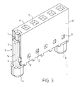
- Figures 1A and 1B respectively represent insulating plugs 1 and 2 intended to be inserted in a housing box 10 ( see figure 3 ) including a single row of connectors
- figures 2A and 2B respectively represent insulating plugs 3 and 4 intended to be inserted in a box ( not shown ) with two contact rows .
- an insulating plug 1, 2, 3, 4 includes at least a first element 5 constituting the essential part or the body of the plug and which is insertable in a bore 11 of box 10 for location of the contacts ( figure 3 ) and a second element 6 defined to be inserted in a corresponding opening of a printed circuit board (not shown) to which the box 10 is connected in order to achieve electrical connection between the electric contacts supported in the box 10 and the printed circuits on the board .
- Elements 5 and 6 of the plug are formed of an electrically insulating material , as a convenient plastic material , and , according to an advantageous feature of the invention, constitute a single part .
- First element 5 has the general shape of an elongate bar having a transverse section which is substantially rectangular , in the shape of a hook or U which defines an axial bore 8 ( in figures 1A and 2A) and 14 ( in figures 1B and 2B).
- the axial bore 14 is closed and extended by a member having the shape of a lug or stud 7 , shaped for closing the corresponding bore 11 of the connector box 10 ( see figure 3 ) , so that the introduction of an electric contact of a connector in the bore 11 is not permitted .
- the insulating plug 2 or 4 according to the invention provides a particular function of locking or coding .
- FIGS 2A and 2B illustrate an embodiment of the invention wherein the insulating plug 3 or 4 has two first elements 5 connected with a second single element 6 , these two elements 5 being intended to be inserted in a box 10 (not shown ) designed to receive two rows of electric contacts which are disposed in parallel one with each other .
- the second element 6 which has for an object to provide a mechanical link between the connector box 10 and a printed circuit board , has the shape of a horseshoe , the thickness of which , in the shown examples , is much smaller than the length of the elements 5, this horseshoe defining an axial bore 13 which :
- the insulating plugs 1 and 3 are more particularly used for providing centering and/or positioning members for electrical contacts in a connector box 10
- the above-described design of the insulating plug i.e. more particularly the presence of bore 8 in the first element 5 and bore 13 in the second element 6 , allows a mechanical link between the contacts of box 10 and the corresponding traces on the printed circuit board , in a very advantageous manner , by means of element 6 of the plug .
- FIG 3 there is shown a connector box 10 .
- the insulating plug 2 shown on figure 1B is in locking position . More particularly , due to lug 7 , plug 2 in box 10 prevents the introduction of an electric contact in its corresponding bore .
- the first element 5 has , on one of its external surfaces , a locking member 9 (which can also be seen on figures 1A through 3 ) having the shape of a protuberance adapted to connect , when inserting the plug , in a corresponding transverse bore 12 of box 10 .
- each element 5 may include a locking member , similar to member 9, or a single element 5 includes the locking member 9.
- the invention provides therefore , in a particular and simple design, an insulating element capable of providing three essential functions , when a connector box with plural electrical contacts has to be electrically connected to a printed circuit board , i.e. a coding function , a positioning function of the electric contacts in their respective recesses of the box , as well as a mechanical link function between the connector box and the printed circuit board .
Landscapes
- Coupling Device And Connection With Printed Circuit (AREA)
- Details Of Connecting Devices For Male And Female Coupling (AREA)
- Connector Housings Or Holding Contact Members (AREA)
Claims (9)
- Un connecteur électrique pour la connexion électrique à une plaquette à circuits imprimés caractérisé en ce qu'il comprend :
un boîtier de logement (10) ayant une pluralité d'alésages (11) pour recevoir et supporter sélectivement dans ceux-ci des contacts électriques pour la connexion électrique à des tracés conducteurs sur ladite plaquette à circuits imprimés ; et
une fiche (1,2,3,4) en matériau isolant ayant un premier élément allongé (5), reçue sélectivement dans un desdits alésages (11) formés pour recevoir un desdits contacts respectifs, ledit premier élément se terminant à une extrémité de celui-ci dans un second élément (6) comprenant un moyen élastique disposé à l'extérieur dudit boîtier (10) pour l'insertion dans une ouverture dans ladite plaquette à circuits imprimés et à son autre extrémité dans un moyen disposé dans ledit alésage (11) comprenant sélectivement un moyen d'accès (8) pour la réception d'un contact électrique complémentaire (7) ou d'un moyen fermé pour empêcher l'insertion d'un contact électrique complémentaire. - Un connecteur selon la revendication 1, caractérisé en ce que le premier élément et le second élément (5,6) de ladite fiche (1,2,3,4) constituent une seule partie.
- Un connecteur selon la revendication 1 ou 2, caractérisé en ce que le premier élément (5) présente une section transversale généralement rectangulaire en forme de U qui définit un alésage axial (8,14) de la fiche (1,2,3,4).
- Un connecteur selon la revendication 1,2 ou 3, caractérisé en ce qu'à l'extrémité de la fiche opposée au second élément (6), ledit moyen d'accès comprend un alésage axial (8) débouchant à l'extrémité dudit premier élément (5).
- Un connecteur selon la revendication 1,2 ou 3, caractérisé en ce qu'à l'extrémité de la fiche opposée au second élément (6), ledit moyen fermé comprend une patte (7) conformée afin de fermer l'alésage correspondant (11) du boîtier de connecteur (10).
- Un connecteur selon l'une quelconque des revendications précédentes, caractérisé en ce que ladite fiche comprend deux desdits premiers éléments (5) reliés à un seul second élément (6), lesdits deux éléments étant agencés pour être insérés dans un boîtier pour recevoir deux rangées sensiblement parallèles de contacts électriques.
- Un connecteur selon l'une quelconque des revendications précédentes, caractérisé en ce que ledit second élément (6) est conformé comme un fer à cheval définissant un alésage axial qui s'étend dans le prolongement de l'alésage axial (8,14) du premier élément (5).
- Un connecteur selon la revendication 6, caractérisé en ce que ledit second élément (6) est conformé comme un fer à cheval définissant deux zones d'appui (6a, 6b) pour lesdits deux premiers éléments (5) dont les alésages axiaux (8,14) débouchent partiellement sur les deux côtés desdites zones d'appui.
- Un connecteur selon l'une quelconque des revendications précédentes, caractérisé en ce que ledit premier élément (5) présente sur une de ses surfaces externes, un élément de verrouillage (9) conformé afin d'être connecté dans un alésage transversal correspondant (12) dudit boîtier (10).
Applications Claiming Priority (2)
| Application Number | Priority Date | Filing Date | Title |
|---|---|---|---|
| FR9011411A FR2666936A1 (fr) | 1990-09-14 | 1990-09-14 | Fiche isolante encliquetable dans un boitier de connecteurs electriques. |
| FR9011411 | 1990-09-14 |
Publications (2)
| Publication Number | Publication Date |
|---|---|
| EP0475846A1 EP0475846A1 (fr) | 1992-03-18 |
| EP0475846B1 true EP0475846B1 (fr) | 1994-12-28 |
Family
ID=9400353
Family Applications (1)
| Application Number | Title | Priority Date | Filing Date |
|---|---|---|---|
| EP91402428A Expired - Lifetime EP0475846B1 (fr) | 1990-09-14 | 1991-09-12 | Fiche isolante pour connecteur électrique et connecteur comportant cette fiche |
Country Status (6)
| Country | Link |
|---|---|
| US (1) | US5178561A (fr) |
| EP (1) | EP0475846B1 (fr) |
| JP (1) | JP2588329B2 (fr) |
| CA (1) | CA2051306A1 (fr) |
| DE (1) | DE69106288D1 (fr) |
| FR (1) | FR2666936A1 (fr) |
Families Citing this family (20)
| Publication number | Priority date | Publication date | Assignee | Title |
|---|---|---|---|---|
| DE4218431C2 (de) * | 1992-06-04 | 1995-04-20 | Cannon Electric Gmbh | Einrichtung zur Verbindung eines Steckverbinders mit einer Leiterplatte |
| US5346412A (en) * | 1993-07-27 | 1994-09-13 | The Whitaker Corporation | Break away key and latch assembly |
| US5356300A (en) * | 1993-09-16 | 1994-10-18 | The Whitaker Corporation | Blind mating guides with ground contacts |
| US5547385A (en) * | 1994-05-27 | 1996-08-20 | The Whitaker Corporation | Blind mating guides on backwards compatible connector |
| US5601453A (en) * | 1994-07-20 | 1997-02-11 | Berg Technology, Inc. | Electrical connector hold-down |
| US5584725A (en) * | 1994-09-29 | 1996-12-17 | Hon Hai Precision Ind. Co., Ltd. | Retention post for use with connector having elongated housing |
| JP3432313B2 (ja) * | 1994-11-29 | 2003-08-04 | 富士通株式会社 | ケーブル接続構造 |
| US5769669A (en) * | 1996-08-26 | 1998-06-23 | Dsc Telecom L.P. | Apparatus and method for keying an electrical assembly with a wiring backplane |
| FR2765035B1 (fr) * | 1997-06-24 | 1999-09-10 | Framatome Connectors Int | Connecteur electrique a codage |
| AU4459200A (en) * | 1999-04-14 | 2000-11-14 | Whitaker Corporation, The | Keying system for electrical connectors |
| US6257926B1 (en) * | 2000-06-21 | 2001-07-10 | Hon Hai Precision Ind. Co., Ltd. | Guiding post with press-fit arrangement |
| US7073953B2 (en) | 2001-08-31 | 2006-07-11 | Amphenol Corporation | Modular fiber optic connection system |
| US6971831B2 (en) * | 2003-04-16 | 2005-12-06 | Lmt Mercer Group, Inc. | Self-locking fastener |
| JP4231729B2 (ja) * | 2003-05-09 | 2009-03-04 | 第一電子工業株式会社 | 誤挿入防止キー及び該キーを使用したコネクタ |
| US6979233B2 (en) * | 2003-11-17 | 2005-12-27 | Tmb | Connector and cross voltage protector for entertainment lighting |
| US20070249236A1 (en) * | 2006-04-20 | 2007-10-25 | Randy Petak | System for ensuring electrical continuity in connection between pre-wired electrical harnesses and conduits |
| US20100212956A1 (en) * | 2007-07-10 | 2010-08-26 | James Parsons | Safety plug for sealing bus bar end connections |
| US8100711B2 (en) * | 2009-06-05 | 2012-01-24 | Tyco Electronics Corporation | Alignment assembly for electrical connectors |
| JP2013089350A (ja) * | 2011-10-14 | 2013-05-13 | Sumitomo Wiring Syst Ltd | 基板用コネクタ |
| CN213816668U (zh) * | 2020-09-14 | 2021-07-27 | 泰科电子(上海)有限公司 | 连接器和连接器壳体 |
Family Cites Families (17)
| Publication number | Priority date | Publication date | Assignee | Title |
|---|---|---|---|---|
| US3177461A (en) * | 1958-03-31 | 1965-04-06 | Adage Inc | Keying device |
| US3325771A (en) * | 1964-04-09 | 1967-06-13 | Elco Corp | Electrical connector module with adjustable polarization |
| US3582867A (en) * | 1969-03-20 | 1971-06-01 | Bendix Corp | Polarization means for electrical connectors |
| US3611272A (en) * | 1970-07-01 | 1971-10-05 | Bendix Corp | Polarizing means for mateable units such as electrical connectors |
| US3714617A (en) * | 1971-09-28 | 1973-01-30 | Bendix Corp | Snap in polarizing member for electrical connectors |
| DE2231480A1 (de) * | 1972-06-27 | 1974-01-10 | Bunker Ramo | Codierbarer steckverbinder |
| DE2455409C3 (de) * | 1974-11-22 | 1981-11-19 | Siemens AG, 1000 Berlin und 8000 München | Codiervorrichtung für Mehrfach-Steckvorrichtungen |
| DE7509792U (de) * | 1975-03-27 | 1975-07-24 | Blaupunkt Werke Gmbh | Mehrpolige codierte Steckverbindung |
| US4159862A (en) * | 1977-12-12 | 1979-07-03 | Fabri-Tek Incorporated | Removable female polarizing guide for electrical connectors |
| US4277126A (en) * | 1979-01-23 | 1981-07-07 | Malco | Releasable key arrangement for an electrical connector |
| US4478469A (en) * | 1982-05-17 | 1984-10-23 | Zero Corporation | Card keying device |
| US4662705A (en) * | 1984-03-19 | 1987-05-05 | Siemens Aktiengesellschaft | Plug-in insertion system for electrical communications apparatus |
| US4568134A (en) * | 1985-02-21 | 1986-02-04 | E. I. Du Pont De Nemours And Company | Printed circuit board keying system |
| US4790763A (en) * | 1986-04-22 | 1988-12-13 | Amp Incorporated | Programmable modular connector assembly |
| GB2193051A (en) * | 1986-07-22 | 1988-01-27 | Messerschmitt Boelkow Blohm | A coding element for a multi- terminal electrical connector |
| US4778411A (en) * | 1987-04-24 | 1988-10-18 | Amp Incorporated | Retention system for connector key member |
| US4822305A (en) * | 1987-08-31 | 1989-04-18 | Amp Incorporated | Programmable keying system |
-
1990
- 1990-09-14 FR FR9011411A patent/FR2666936A1/fr not_active Withdrawn
-
1991
- 1991-08-30 US US07/752,718 patent/US5178561A/en not_active Expired - Fee Related
- 1991-09-12 DE DE69106288T patent/DE69106288D1/de not_active Expired - Lifetime
- 1991-09-12 EP EP91402428A patent/EP0475846B1/fr not_active Expired - Lifetime
- 1991-09-13 JP JP3234480A patent/JP2588329B2/ja not_active Expired - Lifetime
- 1991-09-13 CA CA002051306A patent/CA2051306A1/fr not_active Abandoned
Also Published As
| Publication number | Publication date |
|---|---|
| FR2666936A1 (fr) | 1992-03-20 |
| CA2051306A1 (fr) | 1992-03-15 |
| US5178561A (en) | 1993-01-12 |
| EP0475846A1 (fr) | 1992-03-18 |
| DE69106288D1 (de) | 1995-02-09 |
| JP2588329B2 (ja) | 1997-03-05 |
| JPH04245182A (ja) | 1992-09-01 |
Similar Documents
| Publication | Publication Date | Title |
|---|---|---|
| US5178561A (en) | Insulating plug for use in electric connectors | |
| US4781626A (en) | Keying system for connector families | |
| EP0702429B1 (fr) | Système de polarisation pour assemblage de connecteur électrique autocentré | |
| US5383792A (en) | Insertable latch means for use in an electrical connector | |
| US4895535A (en) | Keyed mountable electrical connectors | |
| KR100360187B1 (ko) | 안내 핀 래칭 시스템을 구비한 전기 커넥터 조립체 | |
| US6227904B1 (en) | Compound type connector | |
| US6004158A (en) | Electrical connector with secondary locking plates | |
| US4666325A (en) | Connector | |
| JP2765812B2 (ja) | 電気コネクタ・アセンブリ | |
| EP0630080B1 (fr) | Fiche modulaire téléphonique à monter sur une plaquette à circuits imprimés | |
| US5700160A (en) | Electrical connector for interconnecting female and male contacts of cables | |
| EP1229612A2 (fr) | Système de détrompage pour connecteur électrique | |
| EP1119078B1 (fr) | Connecteur de faisceau | |
| CA2144704A1 (fr) | Connecteur combine | |
| US6350159B1 (en) | Arrangement for preventing mismating of connectors having different numbers of terminals | |
| EP1248325B1 (fr) | Boîtier isolant et configuration de contact pour prévenir des dommages dans la gorge de contact d'un connecteur à lyre | |
| EP0125786A2 (fr) | Ensemble de connecteur électrique | |
| US6093061A (en) | Electrical connector having terminal insert subassembly | |
| US5449301A (en) | Shunt connector | |
| US6159052A (en) | Electrical connector | |
| US6168473B1 (en) | Clamping structure for communication connector | |
| US6364686B2 (en) | Electrical and/or optical connector with a latching arm | |
| US5738549A (en) | Electrical connector with terminal retention member and bridging contacts | |
| EP0380337B1 (fr) | Connecteur |
Legal Events
| Date | Code | Title | Description |
|---|---|---|---|
| PUAI | Public reference made under article 153(3) epc to a published international application that has entered the european phase |
Free format text: ORIGINAL CODE: 0009012 |
|
| AK | Designated contracting states |
Kind code of ref document: A1 Designated state(s): BE CH DE ES FR GB IT LI LU NL SE |
|
| 17P | Request for examination filed |
Effective date: 19920721 |
|
| 17Q | First examination report despatched |
Effective date: 19940317 |
|
| RAP3 | Party data changed (applicant data changed or rights of an application transferred) |
Owner name: THOMAS & BETTS CORPORATION |
|
| GRAA | (expected) grant |
Free format text: ORIGINAL CODE: 0009210 |
|
| AK | Designated contracting states |
Kind code of ref document: B1 Designated state(s): BE CH DE ES FR GB IT LI LU NL SE |
|
| PG25 | Lapsed in a contracting state [announced via postgrant information from national office to epo] |
Ref country code: IT Free format text: LAPSE BECAUSE OF FAILURE TO SUBMIT A TRANSLATION OF THE DESCRIPTION OR TO PAY THE FEE WITHIN THE PRE;WARNING: LAPSES OF ITALIAN PATENTS WITH EFFECTIVE DATE BEFORE 2007 MAY HAVE OCCURRED AT ANY TIME BEFORE 2007. THE CORRECT EFFECTIVE DATE MAY BE DIFFERENT FROM THE ONE RECORDED.SCRIBED TIME-LIMIT Effective date: 19941228 Ref country code: LI Effective date: 19941228 Ref country code: CH Effective date: 19941228 Ref country code: FR Effective date: 19941228 Ref country code: NL Effective date: 19941228 Ref country code: ES Free format text: THE PATENT HAS BEEN ANNULLED BY A DECISION OF A NATIONAL AUTHORITY Effective date: 19941228 Ref country code: BE Effective date: 19941228 |
|
| REF | Corresponds to: |
Ref document number: 69106288 Country of ref document: DE Date of ref document: 19950209 |
|
| PG25 | Lapsed in a contracting state [announced via postgrant information from national office to epo] |
Ref country code: SE Effective date: 19950328 |
|
| PG25 | Lapsed in a contracting state [announced via postgrant information from national office to epo] |
Ref country code: DE Effective date: 19950329 |
|
| REG | Reference to a national code |
Ref country code: CH Ref legal event code: PL |
|
| EN | Fr: translation not filed | ||
| NLV1 | Nl: lapsed or annulled due to failure to fulfill the requirements of art. 29p and 29m of the patents act | ||
| PG25 | Lapsed in a contracting state [announced via postgrant information from national office to epo] |
Ref country code: LU Free format text: LAPSE BECAUSE OF NON-PAYMENT OF DUE FEES Effective date: 19950930 |
|
| PLBE | No opposition filed within time limit |
Free format text: ORIGINAL CODE: 0009261 |
|
| STAA | Information on the status of an ep patent application or granted ep patent |
Free format text: STATUS: NO OPPOSITION FILED WITHIN TIME LIMIT |
|
| 26N | No opposition filed | ||
| REG | Reference to a national code |
Ref country code: GB Ref legal event code: IF02 |
|
| PGFP | Annual fee paid to national office [announced via postgrant information from national office to epo] |
Ref country code: GB Payment date: 20100927 Year of fee payment: 20 |
|
| REG | Reference to a national code |
Ref country code: GB Ref legal event code: PE20 Expiry date: 20110911 |
|
| PG25 | Lapsed in a contracting state [announced via postgrant information from national office to epo] |
Ref country code: GB Free format text: LAPSE BECAUSE OF EXPIRATION OF PROTECTION Effective date: 20110911 |