EP0475855B1 - Dispositif de coupe de tranches de viandes et/ou de légumes, pour la réalisation de brochettes - Google Patents
Dispositif de coupe de tranches de viandes et/ou de légumes, pour la réalisation de brochettes Download PDFInfo
- Publication number
- EP0475855B1 EP0475855B1 EP91420286A EP91420286A EP0475855B1 EP 0475855 B1 EP0475855 B1 EP 0475855B1 EP 91420286 A EP91420286 A EP 91420286A EP 91420286 A EP91420286 A EP 91420286A EP 0475855 B1 EP0475855 B1 EP 0475855B1
- Authority
- EP
- European Patent Office
- Prior art keywords
- blades
- container
- assembly
- meat
- vegetables
- Prior art date
- Legal status (The legal status is an assumption and is not a legal conclusion. Google has not performed a legal analysis and makes no representation as to the accuracy of the status listed.)
- Expired - Lifetime
Links
Images

Classifications
-
- A—HUMAN NECESSITIES
- A22—BUTCHERING; MEAT TREATMENT; PROCESSING POULTRY OR FISH
- A22C—PROCESSING MEAT, POULTRY, OR FISH
- A22C17/00—Other devices for processing meat or bones
- A22C17/006—Putting meat on skewers
-
- Y—GENERAL TAGGING OF NEW TECHNOLOGICAL DEVELOPMENTS; GENERAL TAGGING OF CROSS-SECTIONAL TECHNOLOGIES SPANNING OVER SEVERAL SECTIONS OF THE IPC; TECHNICAL SUBJECTS COVERED BY FORMER USPC CROSS-REFERENCE ART COLLECTIONS [XRACs] AND DIGESTS
- Y10—TECHNICAL SUBJECTS COVERED BY FORMER USPC
- Y10T—TECHNICAL SUBJECTS COVERED BY FORMER US CLASSIFICATION
- Y10T83/00—Cutting
- Y10T83/687—By tool reciprocable along elongated edge
- Y10T83/6895—Plural reciprocable tools
-
- Y—GENERAL TAGGING OF NEW TECHNOLOGICAL DEVELOPMENTS; GENERAL TAGGING OF CROSS-SECTIONAL TECHNOLOGIES SPANNING OVER SEVERAL SECTIONS OF THE IPC; TECHNICAL SUBJECTS COVERED BY FORMER USPC CROSS-REFERENCE ART COLLECTIONS [XRACs] AND DIGESTS
- Y10—TECHNICAL SUBJECTS COVERED BY FORMER USPC
- Y10T—TECHNICAL SUBJECTS COVERED BY FORMER US CLASSIFICATION
- Y10T83/00—Cutting
- Y10T83/687—By tool reciprocable along elongated edge
- Y10T83/6905—With tool in-feed
- Y10T83/6945—With passive means to guide tool directly
- Y10T83/695—By plural opposed guide surfaces
-
- Y—GENERAL TAGGING OF NEW TECHNOLOGICAL DEVELOPMENTS; GENERAL TAGGING OF CROSS-SECTIONAL TECHNOLOGIES SPANNING OVER SEVERAL SECTIONS OF THE IPC; TECHNICAL SUBJECTS COVERED BY FORMER USPC CROSS-REFERENCE ART COLLECTIONS [XRACs] AND DIGESTS
- Y10—TECHNICAL SUBJECTS COVERED BY FORMER USPC
- Y10T—TECHNICAL SUBJECTS COVERED BY FORMER US CLASSIFICATION
- Y10T83/00—Cutting
- Y10T83/748—With work immobilizer
- Y10T83/7487—Means to clamp work
- Y10T83/7493—Combined with, peculiarly related to, other element
- Y10T83/75—With or to tool guide
-
- Y—GENERAL TAGGING OF NEW TECHNOLOGICAL DEVELOPMENTS; GENERAL TAGGING OF CROSS-SECTIONAL TECHNOLOGIES SPANNING OVER SEVERAL SECTIONS OF THE IPC; TECHNICAL SUBJECTS COVERED BY FORMER USPC CROSS-REFERENCE ART COLLECTIONS [XRACs] AND DIGESTS
- Y10—TECHNICAL SUBJECTS COVERED BY FORMER USPC
- Y10T—TECHNICAL SUBJECTS COVERED BY FORMER US CLASSIFICATION
- Y10T83/00—Cutting
- Y10T83/748—With work immobilizer
- Y10T83/7587—Gapped work-constrainer
-
- Y—GENERAL TAGGING OF NEW TECHNOLOGICAL DEVELOPMENTS; GENERAL TAGGING OF CROSS-SECTIONAL TECHNOLOGIES SPANNING OVER SEVERAL SECTIONS OF THE IPC; TECHNICAL SUBJECTS COVERED BY FORMER USPC CROSS-REFERENCE ART COLLECTIONS [XRACs] AND DIGESTS
- Y10—TECHNICAL SUBJECTS COVERED BY FORMER USPC
- Y10T—TECHNICAL SUBJECTS COVERED BY FORMER US CLASSIFICATION
- Y10T83/00—Cutting
- Y10T83/869—Means to drive or to guide tool
- Y10T83/8873—Straight line motion combined with tilting in plane of stroke
-
- Y—GENERAL TAGGING OF NEW TECHNOLOGICAL DEVELOPMENTS; GENERAL TAGGING OF CROSS-SECTIONAL TECHNOLOGIES SPANNING OVER SEVERAL SECTIONS OF THE IPC; TECHNICAL SUBJECTS COVERED BY FORMER USPC CROSS-REFERENCE ART COLLECTIONS [XRACs] AND DIGESTS
- Y10—TECHNICAL SUBJECTS COVERED BY FORMER USPC
- Y10T—TECHNICAL SUBJECTS COVERED BY FORMER US CLASSIFICATION
- Y10T83/00—Cutting
- Y10T83/869—Means to drive or to guide tool
- Y10T83/8874—Uniplanar compound motion
- Y10T83/8876—Reciprocating plus work approach [e.g., saw type]
Definitions
- the tank is capable of cooperating with any system configured to ensure the racking of wooden pins or picks, through the various layers arranged inside.
- each of the sides of the tray has a plurality of vertical slots allowing the passage of a cutting means for the production of the skewers as such. This cut can be performed either manually or automatically.
- the object of the invention is to remedy these drawbacks in a simple, efficient and rational manner.
- the problem which the invention proposes to solve is to ensure perfect cutting quality without reducing the production rate, that is to say being able to slice all of the layers of meat and / or vegetables from the tank, in a very short period of time.
- the assembly receiving the blades is subject to control means capable of successively subjecting the blades to a movement of penetration inside the tank, to an angular pivoting movement in an arc of a circle. limited to correspond to the entire height of the tank, and to a withdrawal movement, to ensure, by the combination of these movements, the slicing of all the different layers of meat and / or vegetables.
- the blades occupy an angular position defining with respect to the horizontal plane, an acute angle located on the side of the cutting edge of said blades.
- Another problem which the invention proposes to solve is to reduce the forces exerted on the tray, while facilitating cutting, taking into account the movement described by the blades.
- Such a problem is solved in that the assembly is equipped with members capable of alternately subjecting each of the blades to a horizontal vibration movement corresponding to a pushing and pulling force in order to balance the forces exerted on the tank at the time of chopped off.
- the assembly comprises a block mounted with free articulation on a base subject to control means to be moved in translation towards the tank, said block to which the blades are coupled, being subject to means for being angularly pivoted according to the arc of a circle.
- each of the blades respectively to a pushing movement and to a pulling movement
- the block receives the coupling members of the blades in the form of two independent modules mounted with the capacity of linear displacement in translation. limited inside said block, each of said modules being coupled to a control means to be moved linearly and alternately in two opposite directions, each module receiving a series of blades.
- the modules are arranged in superposition, the coupling end parts of the blades being shaped, so that after fixing in the corresponding modules, said blades are arranged in the same horizontal plane.
- the articulation of the block receiving the blades is disposed very substantially at an equal distance from the upper and lower parts of the tray.
- the device finds a particularly advantageous application to a machine for the automatic manufacture of skewers of meat and / or vegetables.
- the cutting device can be used either separately directly in connection with a tray filled with different layers of meat and / or vegetables skewered beforehand, or in combination with an automatic racking-in such as that described in patents FR-A-2537401 and FR -A-2590469.
- FIGS 1, 2, 3 and 4 are schematic views showing the operating principle of the cutting device according to the invention.
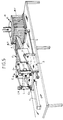
- Figure 5 is a perspective view of the cutting device according to the invention.
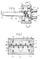
- Figure 6 is a larger scale, a longitudinal sectional view showing an example of coupling of the knife blades in the support block.
- Figure 7 is a cross-sectional view taken along line 7-7 of Figure 6.
- Figure 8 is a schematic plan view in section of the device.
- Figure 9 is a partial perspective view showing the coupling of the knife blades.
- the cutting device comprises an assembly (E) equipped with several blades (1) arranged in correspondence and alignment with slots (B1) presented by a tank (B).
- this tray (B) receives different layers of meat and / or vegetables.
- the assembly (E) is mounted with the ability to move in translation towards the tank (B).
- the blades (1) occupy an angular position ( ⁇ ) which delimits, with respect to the horizontal plane, an acute angle situated on the side of the cutting edge (1a) of said blades.
- the assembly (E) comprises a block (2) mounted with free articulation on a sliding base (3).
- the base is mounted to slide freely on guide rods (4) and is coupled to a control member (5) of the jack type to be moved linearly in translation towards the tank (B).
- the block (2) is arranged to receive the different blades (1).
- the block (2) is subject to control means (6) to be pivoted angularly relative to its hinge axis (7) to vary concomitantly, the angular position of the blades according to the arc movement of circle.
- the control means (6) consist of two vertical cylinders, the rod (6a) of which is coupled to a part of the base, while the barrel (6b) is coupled, in an articulated manner, to a part of the block (2).
- the blades (1) are coupled to the block (2) in combination with members (8) and (9) capable of alternately subjecting each of the blades to a horizontal vibration movement, respectively in a direction of thrust ( P) and traction (T).
- the members (8) and (9) consist of two independent modules mounted with the capacity of linear displacement in translation inside the block (2).
- each module is mounted to slide freely on two parallel guide rods (10-11) and (12-13).
- Each of the modules (8) and (9) is coupled to the rod (14a-15a) of a jack (14-15), to ensure the alternating movement in translation of said modules.
- the jacks (14) and (15) are controlled in the opposite direction, so that when the jack (14) pushes the module (8), the jack (15) pulls the module (9) and vice versa. It therefore appears that the modules (8) and (9) alternately subject one blade in two to a pushing and pulling movement, which makes it possible to balance the forces exerted on the tank at the time of the section as will be indicated in the following description.
- the coupling end part (1b) of the blades (1) is shaped to ensure the positioning of the assembly of the blades in the same horizontal plane.
- the coupling ends (1b) have a heel cooperating in corresponding grooves (8a) (9a) of the modules (8) and (9).
- the blades are fixed in their respective modules for example by means of two threaded rods (16) and (17) engaged in the heels of the blades and each cooperating with nuts.
- the articulation axis (7) of the block (2) receiving the blades is arranged very substantially at an equal distance from the upper and lower parts of the tank (B). It therefore appears that the movement in an arc described by all of the blades and whose center of rotation is formed by the axis (7), is symmetrical with respect to said tank.
- another position of the hinge pin (7) is not excluded, on the sole condition that the circular arc described during the angular pivoting of the blades, and depending on the angular positioning of said blades, allows to take take into account the entire height of the tank.
- the device according to the invention uses blades (1) of all known and appropriate types, in particular rectilinear blades with sharp parts (1c) and (1d) respectively formed at the end of the blade and over the entire lower edge. of the latter.
- This or these cutting parts may also have profiled recesses to facilitate the release of the products as and when cutting.
- the end of each of the blades, on the side of the cutting part (1c), has a bevelled part (1e).
- this bevelled part (1e) is arranged very substantially in a parallel manner to the upper edge of the tank ( Figures 1 and 2). It is the same with regard to the cutting end (1c), which, after angular pivoting of the assembly of the blades, along the arc of a circle, is located very substantially in a manner parallel to the bottom of said tank ( Figure 3 and 4).
- the cutting device according to the invention is controlled by a control unit by being subject to different position sensors to carry out the following operating cycle, as illustrated diagrammatically in Figures 1, 2, 3 and 4 of the drawings.
- the blades (1) are arranged angularly at the angle ( ⁇ ) relative to the horizontal plane where the tank (B) is arranged ( Figure 1).
- the assembly (E) is moved in translation along arrow (F) (FIG. 2), in the direction of the tank, by means of the jack (5), causing the angular penetration of the blades (1) into the different layers of meat and / or vegetables (V), through the slots (B1) of the tank (B). At this stage, part of the layers of meat and / or vegetables (V1) is cut ( Figure 2).
- the jacks (6) are actuated to cause, concomitantly, the angular tilting of the block (2) relative to its axis of articulation (7) which has the effect of moving the blades (1) in an arc (F1) ( Figure 3).
- This arc movement of circle of blades (1) has the effect of cutting the different layers of meat and / or vegetables (V2), over the entire height of the tray on the side of the sharp end (1c) of said blades.
- the assembly is then moved in translation in opposite direction, arrow (F2) (FIG. 4), to complete the cutting of the portions of the layers of meat and / or vegetables (V3) not yet stressed by the blades (1) (FIG. 4).
- the cutting device according to the invention can be used in different ways.
- the device can be used directly with a tray filled with the different layers of meat and / or vegetables skewered beforehand.
- the device is mounted on a support frame arranged to receive the tray, means allowing the angular indexing of the tray to present two of its faces at right angles, successively facing and in alignment with the blades.
- the device can be mounted in combination with an automatic racking device, which has a machine arranged for this purpose.
Landscapes
- Life Sciences & Earth Sciences (AREA)
- Engineering & Computer Science (AREA)
- Wood Science & Technology (AREA)
- Zoology (AREA)
- Food Science & Technology (AREA)
- Meat, Egg Or Seafood Products (AREA)
- Formation And Processing Of Food Products (AREA)
- Fish Paste Products (AREA)
- Food-Manufacturing Devices (AREA)
Priority Applications (1)
| Application Number | Priority Date | Filing Date | Title |
|---|---|---|---|
| AT9191420286T ATE105141T1 (de) | 1990-08-03 | 1991-08-01 | Scheibenschneider fuer fleisch und/oder gemuese zur herstellung von spiessen. |
Applications Claiming Priority (2)
| Application Number | Priority Date | Filing Date | Title |
|---|---|---|---|
| FR9010227 | 1990-08-03 | ||
| FR9010227A FR2665336B1 (fr) | 1990-08-03 | 1990-08-03 | Dispositif de coupe de tranches de viandes et/ou de legumes, pour la realisation de brochettes. |
Publications (2)
| Publication Number | Publication Date |
|---|---|
| EP0475855A1 EP0475855A1 (fr) | 1992-03-18 |
| EP0475855B1 true EP0475855B1 (fr) | 1994-05-04 |
Family
ID=9399595
Family Applications (1)
| Application Number | Title | Priority Date | Filing Date |
|---|---|---|---|
| EP91420286A Expired - Lifetime EP0475855B1 (fr) | 1990-08-03 | 1991-08-01 | Dispositif de coupe de tranches de viandes et/ou de légumes, pour la réalisation de brochettes |
Country Status (7)
| Country | Link |
|---|---|
| US (1) | US5161447A (es) |
| EP (1) | EP0475855B1 (es) |
| AT (1) | ATE105141T1 (es) |
| CA (1) | CA2048135C (es) |
| DE (1) | DE69101894D1 (es) |
| ES (1) | ES2053301T3 (es) |
| FR (1) | FR2665336B1 (es) |
Families Citing this family (11)
| Publication number | Priority date | Publication date | Assignee | Title |
|---|---|---|---|---|
| FI944995A0 (fi) * | 1994-10-24 | 1994-10-24 | Gahmberg Charles | Foerfarande och anordning foer att stycka ett koettstycke |
| FR2760944B1 (fr) * | 1997-03-18 | 1999-04-23 | Michel Emsens | Machine pour la fabrication automatique de brochettes de viande ou de legumes enfilees sur des piques en bois notamment |
| USD406990S (en) | 1998-05-04 | 1999-03-23 | Ocampo Ronald C | Meat slicer |
| EP1238763A1 (en) * | 2001-03-09 | 2002-09-11 | N.V. Techno-Food | Method and apparatus for slicing a number of articles, in particular tomatoes into a plurality of uniform thin slices in a single operation |
| US8069763B2 (en) * | 2004-07-30 | 2011-12-06 | Maxwell Chase Technologies, Llc | Article slicer with integral pick and placer |
| JP4511989B2 (ja) * | 2004-09-17 | 2010-07-28 | マクスウェル チェイス テクノロジーズ エルエルスィー | 物品のスライス方法および装置 |
| US20090158903A1 (en) * | 2007-12-23 | 2009-06-25 | Yan Hoi Yeung | Meat cutting apparatus |
| US8152506B1 (en) | 2008-05-21 | 2012-04-10 | Atoor Khoshaba | Pressure generating device with food compressing attachment |
| ITMO20100232A1 (it) * | 2010-08-05 | 2012-02-06 | Abl S R L | Macchina per la preparazione di pezzi da un frutto di forma ogivale o sferica, quale ad esempio un melone o un cocomero. |
| US20120279371A1 (en) * | 2011-05-03 | 2012-11-08 | Mulchi Jr Charles Lee | Meat cubing and skewering device |
| CN106584566A (zh) * | 2016-11-10 | 2017-04-26 | 四川苍溪梨研究所 | 一种多功能切丁机 |
Family Cites Families (8)
| Publication number | Priority date | Publication date | Assignee | Title |
|---|---|---|---|---|
| US2290169A (en) * | 1936-06-20 | 1942-07-21 | Us Slicing Machine Co | Bread slicing machine |
| US4056026A (en) * | 1975-10-01 | 1977-11-01 | Georges P. Panaritis | Apparatus for cutting meat |
| FR2494092A1 (fr) * | 1980-11-14 | 1982-05-21 | Dolle Jacques | Machine pour le decoupage calibre de viandes et/ou de legumes, et la preparation automatique des brochettes |
| FR2515023B1 (fr) * | 1981-10-28 | 1986-03-21 | Dolle Jacques | Embrocheur pour la preparation des brochettes de viande |
| FR2535169B1 (fr) * | 1982-11-02 | 1985-11-29 | Tolerie Suisse | Procede et machine pour la confection industrielle de brochettes de viande |
| FR2572894A1 (fr) * | 1984-11-13 | 1986-05-16 | Goyheix Laurent | Installation pour le conditionnement et la decoupe de viande et procede pour sa mise en oeuvre |
| US4625364A (en) * | 1985-12-23 | 1986-12-02 | Adams Dean J | Bait cutting device |
| US4934026A (en) * | 1988-09-22 | 1990-06-19 | Marvin Wayne Lynn | Shipping carton for further processing of product |
-
1990
- 1990-08-03 FR FR9010227A patent/FR2665336B1/fr not_active Expired - Lifetime
-
1991
- 1991-07-30 CA CA002048135A patent/CA2048135C/fr not_active Expired - Fee Related
- 1991-08-01 ES ES91420286T patent/ES2053301T3/es not_active Expired - Lifetime
- 1991-08-01 AT AT9191420286T patent/ATE105141T1/de not_active IP Right Cessation
- 1991-08-01 EP EP91420286A patent/EP0475855B1/fr not_active Expired - Lifetime
- 1991-08-01 DE DE69101894T patent/DE69101894D1/de not_active Expired - Lifetime
- 1991-08-05 US US07/739,966 patent/US5161447A/en not_active Expired - Lifetime
Also Published As
| Publication number | Publication date |
|---|---|
| FR2665336A1 (fr) | 1992-02-07 |
| ES2053301T3 (es) | 1994-07-16 |
| CA2048135A1 (fr) | 1992-02-04 |
| CA2048135C (fr) | 2001-12-11 |
| EP0475855A1 (fr) | 1992-03-18 |
| DE69101894D1 (de) | 1994-06-09 |
| US5161447A (en) | 1992-11-10 |
| FR2665336B1 (fr) | 1992-10-23 |
| ATE105141T1 (de) | 1994-05-15 |
Similar Documents
| Publication | Publication Date | Title |
|---|---|---|
| EP0475855B1 (fr) | Dispositif de coupe de tranches de viandes et/ou de légumes, pour la réalisation de brochettes | |
| EP0078232B1 (fr) | Embrocheur pour la préparation de brochettes de viande et/ou autres produits alimentaires | |
| EP0786939B1 (fr) | Machine pour la fabrication automatique de brochettes de viandes et/ou de legumes | |
| EP0230841A1 (fr) | Machine pour la fabrication automatique des brochettes de viande et/ou de légumes enfilés sur des broches | |
| EP0113637B2 (fr) | Machine pour la fabrication automatique de brochettes de viandes, de légumes ou autres | |
| FR2575914A1 (es) | ||
| FR2494092A1 (fr) | Machine pour le decoupage calibre de viandes et/ou de legumes, et la preparation automatique des brochettes | |
| WO1997038613A1 (fr) | Procede et dispositif pour l'ouverture des huitres | |
| FR2574252A1 (fr) | Installation pour la fabrication automatisee de brochettes | |
| EP3331674B1 (fr) | Machine verticale à couper un pain présentant des moyens d'accrochage | |
| WO1998041100A1 (fr) | Machine pour la fabrication automatique de brochettes de viande ou de legumes enfilees sur des piques en bois notamment | |
| EP0155881A1 (fr) | Procédé et installation automatique de tranchage et de détalonnage de meules de fromage | |
| EP2260984B1 (fr) | Méthode et dispositif pour trancher du pain | |
| FR2625130A1 (fr) | Trancheuse longitudinale a bois et installation de tranchage | |
| CA2202035C (fr) | Machine pour la fabrication automatique de brochettes de viandes et/ou de legumes | |
| FR2537401A1 (fr) | Machine pour la fabrication automatique de brochettes de viandes, de legumes ou autres | |
| FR2684036A1 (fr) | Machine pour le tranchage automatique de produits alimentaires. | |
| FR2760945A1 (fr) | Procede de fabrication de brochettes et machines pour sa mise en oeuvre | |
| EP2647292B1 (fr) | Dispositif de distribution de piques à brochettes | |
| FR2642938A1 (fr) | Dispositif de distribution et d'espacement automatiques de batonnets ou piques pour machine a brochettes | |
| EP0601936A1 (fr) | Dispositif d'émiettage pour pressoir de type horizontal | |
| FR3012356A1 (fr) | Dispositif de decoupe tridimensionnelle | |
| FR2480169A1 (fr) | Trancheuse pour produits alimentaires | |
| WO2011151607A1 (fr) | Segment de palette et palette comprenant au moins deux tels segments | |
| FR2725929A1 (fr) | Procede d'evidage d'un pain moule par decoupe d'un cylindre de mie, et de tranchage de ce cylindre, et dispositif pour la mise en oeuvre du procede |
Legal Events
| Date | Code | Title | Description |
|---|---|---|---|
| PUAI | Public reference made under article 153(3) epc to a published international application that has entered the european phase |
Free format text: ORIGINAL CODE: 0009012 |
|
| 17P | Request for examination filed |
Effective date: 19911018 |
|
| AK | Designated contracting states |
Kind code of ref document: A1 Designated state(s): AT BE CH DE DK ES GB GR IT LI LU NL SE |
|
| 17Q | First examination report despatched |
Effective date: 19930830 |
|
| GRAA | (expected) grant |
Free format text: ORIGINAL CODE: 0009210 |
|
| AK | Designated contracting states |
Kind code of ref document: B1 Designated state(s): AT BE CH DE DK ES GB GR IT LI LU NL SE |
|
| PG25 | Lapsed in a contracting state [announced via postgrant information from national office to epo] |
Ref country code: DK Effective date: 19940504 Ref country code: IT Free format text: LAPSE BECAUSE OF FAILURE TO SUBMIT A TRANSLATION OF THE DESCRIPTION OR TO PAY THE FEE WITHIN THE PRE;WARNING: LAPSES OF ITALIAN PATENTS WITH EFFECTIVE DATE BEFORE 2007 MAY HAVE OCCURRED AT ANY TIME BEFORE 2007. THE CORRECT EFFECTIVE DATE MAY BE DIFFERENT FROM THE ONE RECORDED.SCRIBED TIME-LIMIT Effective date: 19940504 Ref country code: SE Free format text: THE PATENT HAS BEEN ANNULLED BY A DECISION OF A NATIONAL AUTHORITY Effective date: 19940504 Ref country code: DE Effective date: 19940504 Ref country code: NL Effective date: 19940504 Ref country code: GR Free format text: LAPSE BECAUSE OF FAILURE TO SUBMIT A TRANSLATION OF THE DESCRIPTION OR TO PAY THE FEE WITHIN THE PRESCRIBED TIME-LIMIT Effective date: 19940504 Ref country code: GB Effective date: 19940504 Ref country code: AT Effective date: 19940504 |
|
| REF | Corresponds to: |
Ref document number: 105141 Country of ref document: AT Date of ref document: 19940515 Kind code of ref document: T |
|
| REF | Corresponds to: |
Ref document number: 69101894 Country of ref document: DE Date of ref document: 19940609 |
|
| REG | Reference to a national code |
Ref country code: ES Ref legal event code: FG2A Ref document number: 2053301 Country of ref document: ES Kind code of ref document: T3 |
|
| PG25 | Lapsed in a contracting state [announced via postgrant information from national office to epo] |
Ref country code: BE Effective date: 19940831 Ref country code: CH Effective date: 19940831 Ref country code: LI Effective date: 19940831 Ref country code: LU Free format text: LAPSE BECAUSE OF NON-PAYMENT OF DUE FEES Effective date: 19940831 |
|
| NLV1 | Nl: lapsed or annulled due to failure to fulfill the requirements of art. 29p and 29m of the patents act | ||
| GBV | Gb: ep patent (uk) treated as always having been void in accordance with gb section 77(7)/1977 [no translation filed] |
Effective date: 19940504 |
|
| BERE | Be: lapsed |
Owner name: EMSENS ANTOINE S.A.R.L. Effective date: 19940831 |
|
| PLBE | No opposition filed within time limit |
Free format text: ORIGINAL CODE: 0009261 |
|
| STAA | Information on the status of an ep patent application or granted ep patent |
Free format text: STATUS: NO OPPOSITION FILED WITHIN TIME LIMIT |
|
| 26N | No opposition filed | ||
| REG | Reference to a national code |
Ref country code: CH Ref legal event code: PL |
|
| PGFP | Annual fee paid to national office [announced via postgrant information from national office to epo] |
Ref country code: ES Payment date: 20060818 Year of fee payment: 16 |
|
| REG | Reference to a national code |
Ref country code: ES Ref legal event code: FD2A Effective date: 20070802 |
|
| PG25 | Lapsed in a contracting state [announced via postgrant information from national office to epo] |
Ref country code: ES Free format text: LAPSE BECAUSE OF NON-PAYMENT OF DUE FEES Effective date: 20070802 |