EP0475923B1 - Vorrichtung zur Kraftregulierung der Niederhalter einer Presse - Google Patents
Vorrichtung zur Kraftregulierung der Niederhalter einer Presse Download PDFInfo
- Publication number
- EP0475923B1 EP0475923B1 EP91870129A EP91870129A EP0475923B1 EP 0475923 B1 EP0475923 B1 EP 0475923B1 EP 91870129 A EP91870129 A EP 91870129A EP 91870129 A EP91870129 A EP 91870129A EP 0475923 B1 EP0475923 B1 EP 0475923B1
- Authority
- EP
- European Patent Office
- Prior art keywords
- blank
- holder
- pressure
- fluid
- jack
- Prior art date
- Legal status (The legal status is an assumption and is not a legal conclusion. Google has not performed a legal analysis and makes no representation as to the accuracy of the status listed.)
- Expired - Lifetime
Links
- 230000001105 regulatory effect Effects 0.000 title claims abstract description 9
- 239000012530 fluid Substances 0.000 claims abstract description 32
- 238000005259 measurement Methods 0.000 claims description 11
- 238000000034 method Methods 0.000 claims description 9
- 238000006073 displacement reaction Methods 0.000 claims description 8
- 230000008569 process Effects 0.000 claims description 6
- 230000004044 response Effects 0.000 claims description 2
- 208000018999 crinkle Diseases 0.000 claims 1
- 239000011159 matrix material Substances 0.000 description 5
- 238000013461 design Methods 0.000 description 4
- 238000010586 diagram Methods 0.000 description 3
- 230000008901 benefit Effects 0.000 description 2
- 230000000295 complement effect Effects 0.000 description 2
- 230000000694 effects Effects 0.000 description 2
- 230000009467 reduction Effects 0.000 description 2
- 238000012360 testing method Methods 0.000 description 2
- 230000008859 change Effects 0.000 description 1
- 125000004122 cyclic group Chemical group 0.000 description 1
- 230000001419 dependent effect Effects 0.000 description 1
- 238000011161 development Methods 0.000 description 1
- 239000013536 elastomeric material Substances 0.000 description 1
- 230000001939 inductive effect Effects 0.000 description 1
- 238000004519 manufacturing process Methods 0.000 description 1
- 230000007246 mechanism Effects 0.000 description 1
- 239000002184 metal Substances 0.000 description 1
- 230000003287 optical effect Effects 0.000 description 1
- 238000003825 pressing Methods 0.000 description 1
- 230000000284 resting effect Effects 0.000 description 1
- 230000000007 visual effect Effects 0.000 description 1
Images


Classifications
-
- B—PERFORMING OPERATIONS; TRANSPORTING
- B21—MECHANICAL METAL-WORKING WITHOUT ESSENTIALLY REMOVING MATERIAL; PUNCHING METAL
- B21D—WORKING OR PROCESSING OF SHEET METAL OR METAL TUBES, RODS OR PROFILES WITHOUT ESSENTIALLY REMOVING MATERIAL; PUNCHING METAL
- B21D24/00—Special deep-drawing arrangements in, or in connection with, presses
- B21D24/04—Blank holders; Mounting means therefor
- B21D24/08—Pneumatically or hydraulically loaded blank holders
-
- B—PERFORMING OPERATIONS; TRANSPORTING
- B21—MECHANICAL METAL-WORKING WITHOUT ESSENTIALLY REMOVING MATERIAL; PUNCHING METAL
- B21D—WORKING OR PROCESSING OF SHEET METAL OR METAL TUBES, RODS OR PROFILES WITHOUT ESSENTIALLY REMOVING MATERIAL; PUNCHING METAL
- B21D22/00—Shaping without cutting, by stamping, spinning, or deep-drawing
- B21D22/20—Deep-drawing
- B21D22/22—Deep-drawing with devices for holding the edge of the blanks
Definitions
- the present invention relates to a fluidic device for regulating the force of blank holder in a stamping press.
- a stamping press essentially comprises a table on which is fixed a matrix with an imprint whose design is that of the external surface of the piece to be stamped, a blank holder used to fix the sheet blank to be stamped and a punch fixed to the slide of the press, this punch having a design complementary to that of the imprint of the die.
- the blank holder exerts a clamping pressure on the sides of the blank in order to prevent wrinkling of the sheet following the shrinking effect.
- the clamping pressure exerted by the blank holder can also be used to create a high tension in the stamped skirt in the case of conical stamps or for calibration by drawing on a punch for example.
- the blank holder and the punch can be mounted above the die, the clamping pressure and the drawing force acting downwards, or be mounted below the die , in which case the clamping pressure and the drawing force are exerted upwards.
- the blank holder is consisting of a moving part actuated by hydraulic cylinders or by a drive mechanism (see for example GB-A-1 481 202). These devices provide a clamping force which is usually kept constant during the stamping operation while the stamping force exerted on the punch varies as a function of the stroke of the punch passing through a maximum.
- the jacks of a hydraulic press mounted in a known manner above a blank holder generally work at the end of the travel and, therefore, the volume of fluid to be compressed is very large, which has the consequence of very significantly limiting the dynamic performance of a pressure regulation system acting directly on the blank holding cylinders of the press.
- Mechanical control of the blank holder, for its part, does little to regulate the pressure during the cycle, and the addition of a passive hydraulic system, as has already been done, only serves to stabilize the pressure tightening and does not change the impossibility of regulating the pressure during the cycle.
- the blank holder rests on columns which bear on the hydraulic or pneumatic cushion of the press.
- a hydraulic cushion offers only poor dynamic performance in terms of force regulation and a pneumatic cushion offers no possibility of controlled variation of the pressure during the cycle.
- the known presses offer only limited possibilities of varying the strength of the blank holder in a controlled manner during the stamping cycle.
- the object of the present invention is to propose a device adaptable to a conventional mechanical or hydraulic press and making it possible to vary the force of the blank holder in a controlled manner and with excellent dynamic performance.
- At least one stop is placed on the press so as to limit the travel of the sliding member towards the press table.
- the jack receives the fluid under pressure from at least one adjustment valve arranged to adjust the pressure of the fluid in response to an adjustment signal representing the difference between the effective pressure of the fluid at the outlet of the valve and at less a pressure setpoint determined from at least one measurement signal generated by at least one measurement sensor and representing at least one parameter of the drawing process, so that when the movement of the sliding member is stopped by the stop before the blank holder has come into contact with a blank placed on or against the matrix, the force exerted by the blank holder on said blank is determined by the pressure of the fluid injected into the cylinder and varies during the stamping cycle so that the punch works with constant force during the stamping process so as to keep the tool closed during the drawing process. stamping.
- the pressure of the fluid in the fluidic device varies so that the variation of the pressure force of the blank holder whose profile corresponds to the inverted profile of a curve representing the variation of the force a punch in the event that the blank holder pressure is kept constant.
- the invention offers various interesting possibilities for solving practical problems in the production of stampings.
- the invention makes it possible to maximize the drawing force in order to minimize the dimensions of the blank, or to suppress the elastic return of a stamping in order to obtain high precision on the stamped part, or else to avoid the appearance of folds in the skirt of the stamping and thus maximize the reduction ratio achievable in one pass, that is to say the ratio between the diameter of the blank and the diameter of the punch.
- Figure 1 is a sectional view of a typical hydraulic press in which is incorporated an exemplary device according to the invention.
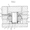
- Figure 2 is a view similar to that of Figure 1, showing the machine at the end of stamping operation.
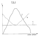
- FIG. 3 is a diagram showing an example of variation of the hold-down force produced with the device according to the invention.
- FIG. 4 is an overall diagram of a regulation system organized around the device according to the invention.
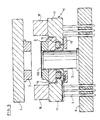
- FIG. 5 illustrates the application of the device according to the invention in a second type of typical hydraulic press.
- FIG. 1 there is shown an exemplary stamping press, of the hydraulic type.
- This press comprises a table 1 carrying a die 2 with an imprint whose design is that of the outer surface of a part to be stamped.
- the reference sign 3 designates a blank holder intended to exert pressure on the sheet blank to be stamped
- the reference sign 4 designates the press slide
- the reference sign 5 designates a punch having a design complementary to that of the 'imprint of the die
- the reference sign 6 designates the slide of the punch in order to bring the punch 5 closer to and away from the die 2.
- the blank holder 3 is not fixed directly to the press slide 4, but by means of an adjustment device 10, an exemplary embodiment of which is described below.
- This device comprises a body 11 fixed (for example by screws not shown) to the slide 4 of the press.
- the body 11 In the body 11 are housed for compact fluid cylinders 12 with very short stroke.
- the pistons 15 of the jacks 12 bear on a plate 16 fixed to the blank holder 3 by means not shown.
- the plate 16 is guided and locked relative to the body 11 by any means (not shown), commonly used in press tools.
- the body 11 comprises at least one conduit 13 for supplying a pressurized fluid coming from any source of fluid (source of press fluid or autonomous group).
- the body 11 carries a connection plate 17 comprising several channels 14 for connecting several jacks 12 to a supply duct 13 interchangeably. Connections can be changed simply by replacing one connection plate with another. The seal between the connection plate 17 and the body 11 is ensured by means of seals "0" for example.
- the cylinders are in principle single acting cylinders.
- the cylinders can also be annular cylinders whose axis coincides with the axis of the tool or be pockets of elastomeric material, for example, or any other device capable of producing an axial pressure using a fluid under pressure.
- the slide 4 of the press descends, driving the body 11, the plate 16 and the blank holder 3 towards the table 1 of the machine.
- the body 11 continues its downward movement until it touches a stopper 18 which is here fixed on the machine table.
- the height of the stop 18 and the clearance between the body 11 and the plate 16 are adjusted so that the pressing force is exerted on the stop 18 and not point on the die 2 or on the blank 100 placed on the die .
- the jacks 12 are pressurized by injecting a fluid therein while the punch 5 is moved down to come and make a stamping ( Figure 2).
- Curve A in FIG. 3 represents a typical variation in the force of a punch when the force of the blank holder is kept constant as in the known technique.
- Curve B represents an exemplary variation curve of the hold-down force which the device according to the invention makes it possible to obtain.
- the jacks 12 being very compact, the volume of fluid which they contain is very reduced and that consequently it is possible to produce significant and steep variations in the force. with very low fluid flow rates.
- the regulation device produced according to the invention is therefore a very sensitive dynamic system, which makes it possible to carry out fine and very reliable dynamic control and regulation.
- One or more pressure sensors can be provided to measure the pressure in the cylinders 12: one can for example use piezoelectric pressure sensors type 4283A200 from the company Kistler.
- a displacement sensor can be provided to measure the position of the punch 5 relative to the die 2: it is possible, for example, to use a displacement sensor of the Temposonic brand having a measurement accuracy of 0.1 mm.
- Another displacement sensor can be provided to measure the difference between the blank holder 3 and the matrix 2: it is possible, for example, to use an inductive displacement sensor having a high precision of 0.01 mm.
- a force sensor, of the piezoelectric type for example, can be provided between the punch 5 and the slide to measure the drawing force.
- the electrical voltage or current signals produced by the aforementioned sensors and which are proportional to the quantities measured, are used to continuously generate a pressure setpoint so as to regulate the hold-down force at any time at the required value in according to the dynamic parameters of the press.
- FIG. 4 is an overall diagram of a dynamic regulation organized around the pressure regulator device according to the invention.
- An independent hydraulic group 21 or the hydraulic system of the machine delivers a pressurized fluid to the jacks 12 via an adjustment valve 22, for example a high performance servo valve such as a Moog valve series D760 or a proportional valve.
- a regulation card 23 receiving at a first input a signal P representing the measurement of the pressure at the output of the valve 22 carried out by means of a pressure sensor 24.
- the card 23 receives a setpoint signal C representing a pressure setpoint.
- the regulation card 23 is arranged to determine the difference between the measured pressure and the pressure setpoint and to produce an adjustment signal R for the valve 22 so as to reduce said pressure difference to zero.
- the pressure setpoint C is determined by a processor 20 from the measurement signals M produced by the sensor (s) by performing mathematical calculations and / or logic tests adapted to the particular application concerned.
- the device of the invention it is also possible, thanks to the device of the invention, to reduce the effective force of blank holder to the minimum value strictly necessary to prevent the appearance of folds between blank holder and matrix and thus to maximize the reduction ratio ( diameter of the blank relative to the diameter of the punch) achievable in one pass.
- This result can be achieved thanks to the invention by measuring the distance between the die 2 and the blank holder 3 using a displacement sensor. Indeed, the distance between the matrix and the blank holder increases as soon as folds appear. From the measurement of this distance, the processor generates the pressure setpoint according to a regulation logic capable of minimizing the pressure of hold-down to the value just necessary to prevent the development of folds.
- the device can also be applied to control the folds appearing in the skirt of a conical stamp, that is to say that an appropriate profile of blank holder force is developed comprising for example, a cyclic variation with an evolving average value, that is to say that the force of the blank holder is regulated from the measurement of the amplitude of the folds in the skirt of the stamping, measurement provided for example by sensors of displacements or by an optical system analyzing the visual appearance of the skirt during stamping.
- the device according to the invention is obviously also adaptable to a stamping press in which the punch and the blank holder are mounted below the die.
- Figure 5 illustrates this application.
- the body 11 of the device according to the invention rests here on the sliding columns 4.
- the blank holder 3 rests on the movable member 16 which cooperates with the pistons 15 of the jacks 12 housed in the body 11 as described above.
- the stops 18 intended to limit the distance between the slide 1 and the body 11 are here carried by the body 11.
- the operation of the device for adjusting the pressure of the blank holder is in all respects similar to that of the embodiment of the Figure 1.
- the device according to the invention can be produced in various embodiments. It can be made to fit and be mounted on an existing stamping press as in the embodiment described by way of example in the above.
- the device according to the invention can also be integrated into any new stamping press, in various embodiments.
Landscapes
- Engineering & Computer Science (AREA)
- Mechanical Engineering (AREA)
- Shaping Metal By Deep-Drawing, Or The Like (AREA)
- Press Drives And Press Lines (AREA)
- Mounting, Exchange, And Manufacturing Of Dies (AREA)
- Casting Or Compression Moulding Of Plastics Or The Like (AREA)
- Control Of Presses (AREA)
Claims (7)
- Tiefziehpresse mit einem Tisch (1), auf dem eine Matritze (2) befestigt ist, einem Gleitkörper (4), der so gelagert ist, daß er auf den Tisch (1) zu bewegbar und von ihm weg bewegbar ist, einem Niederhalter (3), der an dem Gleitkörper befestigt ist, einem Stempel (5), der an einem Stempelträger (6) so angebracht ist, daß er entlang der Achse der Matrize (2) auf den Tisch (1) zu bewegbar und von ihm weg bewegbar ist, einer Strömungsmittelvorrichtung mit mindestens einem Kompaktstellmotor, der zwischen dem Niederhalter (3) und dem Gleitkörper (4) angeordnet ist, wobei das Gehäuse des Stellmotors mit dem Gleitkörper integral ausgebildet ist und der Kolben des Stellmotors an dem Niederhalter so befestigt ist, daß der Niederhalter (3) bezüglich des Gleitkörpers (4) verstellt wird, wenn der Stellmotor mit einem Druckmittel beaufschlagt wird, dadurch gekennzeichnet, daß sie mindestens einen Anschlag (18) aufweist, der so angeordnet ist, daß er die Bewegung des Gleitkörpers (4) auf den Tisch zu begrenzt, und der Stellmotor das Druckmittel von zumindest einem Regelventil (22) erhält, das den Druck des Strömungsmittels in Abhängigkeit von einem Regelsignal (R) regelt, welches den Unterschied zwischen dem Ist-Druck (P) des Strömungsmittels am Ausgang des Ventils und mindestens einem Druck-Soll-Wert (C) darstellt, der ausgehend von mindestens einem Meßsignal (M) bestimmt wird, welches durch mindestens einen Meßfühler (24) erzeugt wird und mindestens einen Parameter des Tiefziehvorganges darstellt, derart, daß, wenn die Verstellung des Gleitkörpers (4) durch den Anschlag (18) unterbrochen wird, ehe der Niederhalter mit einer auf der oder gegen die Matrize angeordneten Scheibe in Berührung gelangt, die von dem Niederhalter auf die Scheibe ausgeübte Kraft durch den Strömungsmitteldruck, mit dem der Stellmotor (12) beaufschlagt wurde, bestimmt wird und sich im Verlauf des Tiefziehzyklus so ändert, daß der Stempel mit einer konstanten Kraft während des Tiefziehvorganges arbeitet, und daß das Werkzeug während des Tiefziehvorganges geschlossen gehalten wird.
- Tiefziehpresse nach Anspruch 1, dadurch gekennzeichnet, daß der Anschlag (18) auf dem Tisch (1) der Presse angebracht ist.
- Tiefziehpresse nach Anspruch 1, dadurch gekennzeichnet, daß der Anschlag (18) mit dem Gleitkörper (4), der den Niederhalter mitnimmt, integral ausgebildet ist.
- Tiefziehpresse nach einem der vorhergehenden Ansprüche, dadurch gekennzeichnet, daß der oder die Kompaktstellmotoren in einem Gehäuse (11) untergebracht sind, das auf dem Gleitkörper (4) so angebracht ist, daß es von diesem mitgenommen wird, wobei das Gehäuse mindestens eine Leitung (13) für die Zufuhr eines Druckmittels zu jedem Stellmotor aufweist, wobei der Kolben (15) jedes Stellmotors an dem Niederhalter (3) so befestigt ist, daß der Niederhalter bezüglich des Gehäuses (11) verstellt wird, wenn der Stellmotor oder die Stellmotoren mit einem Druckmittel beaufschlagt wird bzw. werden.
- Tiefziehpresse nach einem der vorhergehenden Ansprüche, dadurch gekennzeichnet, daß der Druck-Sollwert (C) permanent durch einen Prozessor (20) berechnet wird.
- Verfahren zum Regeln des Strömungsmitteldrucks in der Strömungsmittelvorrichtung, die nach einem der vorhergehenden Ansprüche vorgesehen ist, dadurch gekennzeichnet, daß der Strömungsmitteldruck in der Strömungsmittelvorrichtung entsprechend der Änderung der Druckkraft des Niederhalters (3) geändert wird, deren Profil dem inversen Profil einer Kurve entspricht, welche die Änderung der Kraft eines Stempels für den Fall darstellt, daß die Druck- kraft des Niederhalters konstant gehalten wird.
- Verfahren zum Regeln des Strömungsmitteldrucks in der Strömungsmittelvorrichtung, die nach einem der Ansprü- che 1 bis 5 vorgesehen ist, dadurch gekennzeichnet, daß der Strömungsmitteldruck in der Strömungsmittelvorrichtung in Abhängigkeit von dem Abstand zwischen dem Niederhalter und der Matrize so geändert wird, daß die Druckkraft des Niederhalters auf dem Mindestwert gehalten wird, der zur Vermeidung von Falten unbedingt erforderlich ist.
Applications Claiming Priority (2)
| Application Number | Priority Date | Filing Date | Title |
|---|---|---|---|
| BE9000841A BE1004564A3 (fr) | 1990-08-30 | 1990-08-30 | Dispositif de regulation de la force de serre-flan dans une presse. |
| BE9000841 | 1990-08-30 |
Publications (2)
| Publication Number | Publication Date |
|---|---|
| EP0475923A1 EP0475923A1 (de) | 1992-03-18 |
| EP0475923B1 true EP0475923B1 (de) | 1994-07-06 |
Family
ID=3884919
Family Applications (1)
| Application Number | Title | Priority Date | Filing Date |
|---|---|---|---|
| EP91870129A Expired - Lifetime EP0475923B1 (de) | 1990-08-30 | 1991-08-22 | Vorrichtung zur Kraftregulierung der Niederhalter einer Presse |
Country Status (6)
| Country | Link |
|---|---|
| US (1) | US5477723A (de) |
| EP (1) | EP0475923B1 (de) |
| AT (1) | ATE108102T1 (de) |
| BE (1) | BE1004564A3 (de) |
| DE (1) | DE69102744T2 (de) |
| ES (1) | ES2065665T3 (de) |
Cited By (1)
| Publication number | Priority date | Publication date | Assignee | Title |
|---|---|---|---|---|
| CN109290477A (zh) * | 2018-09-28 | 2019-02-01 | 浙江龙文精密设备股份有限公司 | 异径两片罐罐身的成型工艺 |
Families Citing this family (26)
| Publication number | Priority date | Publication date | Assignee | Title |
|---|---|---|---|---|
| DE4232161A1 (de) * | 1992-09-25 | 1994-03-31 | Audi Ag | Verfahren zum Herstellen eines Hohlkörpers |
| JP2812201B2 (ja) * | 1994-07-15 | 1998-10-22 | トヨタ自動車株式会社 | プレス装置 |
| US5626048A (en) * | 1995-11-20 | 1997-05-06 | Can Industry Products, Inc. | Method and apparatus for forming cup-shaped members |
| BE1010313A3 (fr) * | 1996-05-30 | 1998-06-02 | S C Rech Et Dev Groupe Cockeri | Amelioration au systeme de regulation de la force de serre-flan dans une presse. |
| DE19641411A1 (de) * | 1996-10-08 | 1998-04-09 | Dieffenbacher Gmbh Maschf | Hydraulische Tiefzieheinrichtung |
| US5941110A (en) * | 1997-05-12 | 1999-08-24 | Northern University | Adaptive method and apparatus for forming tailor welded blanks |
| US6014883A (en) * | 1998-06-08 | 2000-01-18 | Can Industry Products, Inc. | Apparatus and method for forming cup-shaped members |
| DK173519B1 (da) * | 1999-06-21 | 2001-01-29 | Hydraulico As | Værktøj til presseformgivning af metalplade og fremgangsmåde til regulering af et fladetryk ved brug af sådant værktøj |
| US6244091B1 (en) | 1999-11-10 | 2001-06-12 | Can Industry Products, Inc. | Apparatus and method for forming cup-shaped members |
| NL1021738C2 (nl) * | 2002-10-24 | 2004-04-27 | Tno | Werkwijze en inrichting voor het reduceren van plooivorming bij dieptrekken. |
| DE102005021028B4 (de) * | 2004-06-02 | 2009-06-25 | Schuler Pressen Gmbh & Co. Kg | Presse zum Schneiden von hochfesten Blechen |
| CA2568685A1 (en) * | 2004-06-02 | 2005-12-22 | Stefan Fellenberg | Method and device for cutting high-tensile sheet metal, and press |
| DE102004038208B4 (de) * | 2004-08-05 | 2008-11-13 | Daimler Ag | Verfahren und Werkzeugeinrichtung zum Umformen |
| US20080307849A1 (en) * | 2004-11-26 | 2008-12-18 | Agency For Science, Technology And Research | Method And Apparatus For Forming Microstructures |
| JP4102389B2 (ja) * | 2005-06-24 | 2008-06-18 | ファナック株式会社 | サーボダイクッションの制御装置 |
| EP1882564B1 (de) * | 2006-07-26 | 2012-04-11 | Heidelberger Druckmaschinen AG | Bogenstanz- und -prägemaschine mit regulierbarem Stanz- oder Prägedruck |
| FR2955272B1 (fr) * | 2010-01-18 | 2012-04-27 | Peugeot Citroen Automobiles Sa | Outil d'emboutissage d'une tole pour la mise en forme d'une piece de carrosserie |
| DE102010019323B4 (de) * | 2010-05-03 | 2012-03-01 | Schuler Pressen Gmbh & Co. Kg | Vorrichtung und Verfahren zur Herstellung von Dosenkörpern |
| DE102012018606A1 (de) * | 2012-09-20 | 2014-03-20 | Fraunhofer-Gesellschaft zur Förderung der angewandten Forschung e.V. | Tiefziehwerkzeug und Verfahren zum Tiefziehen eines Werkstückes |
| CN104138953A (zh) * | 2014-06-23 | 2014-11-12 | 东莞市正强五金电子有限公司 | 磁控管用排气管的制造方法和磁控管用排气管 |
| DE102015016406A1 (de) * | 2015-12-18 | 2017-06-22 | Heinz Schwarz Gmbh & Co. Kg | Ziehwerkzeug zur Umformung von Werkstücken |
| CN106001227A (zh) * | 2016-06-28 | 2016-10-12 | 芜湖新泉汽车饰件系统有限公司 | 一种汽车门板冲压装置 |
| CN109647972B (zh) * | 2018-10-29 | 2024-08-02 | 东莞市超业精密设备有限公司 | 一种铝膜冲壳成型系统 |
| CN109108156B (zh) * | 2018-10-29 | 2024-07-30 | 东莞市超业精密设备有限公司 | 一种锂电池铝膜压紧冲壳装置 |
| JP7261984B2 (ja) * | 2019-09-18 | 2023-04-21 | パナソニックIpマネジメント株式会社 | 打ち抜き装置 |
| JP2025039188A (ja) * | 2023-09-08 | 2025-03-21 | アイダエンジニアリング株式会社 | アシスト絞り成形装置 |
Family Cites Families (13)
| Publication number | Priority date | Publication date | Assignee | Title |
|---|---|---|---|---|
| US1619069A (en) * | 1924-08-06 | 1927-03-01 | Marquette Tool & Mfg Co | Blank-holding means |
| US2214635A (en) * | 1936-09-16 | 1940-09-10 | Hydraulic Press Corp Inc | Metal drawing press |
| US2290743A (en) * | 1939-12-11 | 1942-07-21 | Hydraulic Dev Corp Inc | Blank-holder press |
| US2294451A (en) * | 1940-03-29 | 1942-09-01 | Hydraulic Dev Corp Inc | Blank holder and die cushion cylinder having separate adjustable pressures |
| DE2403532A1 (de) * | 1974-01-25 | 1975-08-07 | Schuler Gmbh L | Vorrichtung zur begrenzung des arbeitsweges eines pressenstoessels |
| GB1481202A (en) * | 1976-03-29 | 1977-07-27 | Metal Box Co Ltd | Deep drawing |
| US4316379A (en) * | 1978-09-12 | 1982-02-23 | Mts Systems Corporation | Deep drawing press with blanking and draw pad pressure control |
| US4331017A (en) * | 1980-12-11 | 1982-05-25 | Joseph Bulso, Jr. | High reduction process and apparatus |
| US4392368A (en) * | 1980-12-17 | 1983-07-12 | Saab-Scania Aktiebolag | Arrangement for presses |
| FR2564339B1 (fr) * | 1984-05-17 | 1987-12-24 | Usinor | Procede et dispositif d'emboutissage de toles. |
| SU1196075A1 (ru) * | 1984-08-28 | 1985-12-07 | Предприятие П/Я М-5671 | Штамп дл ступенчатой выт жки листовых заготовок |
| US4745792A (en) * | 1986-10-14 | 1988-05-24 | Aluminum Company Of America | Blankholder for a draw press |
| SU1574320A1 (ru) * | 1988-04-26 | 1990-06-30 | Калужский филиал МГТУ им.Н.Э.Баумана | Устройство дл выт жки |
-
1990
- 1990-08-30 BE BE9000841A patent/BE1004564A3/fr not_active IP Right Cessation
-
1991
- 1991-08-22 AT AT91870129T patent/ATE108102T1/de not_active IP Right Cessation
- 1991-08-22 ES ES91870129T patent/ES2065665T3/es not_active Expired - Lifetime
- 1991-08-22 EP EP91870129A patent/EP0475923B1/de not_active Expired - Lifetime
- 1991-08-22 DE DE69102744T patent/DE69102744T2/de not_active Expired - Lifetime
- 1991-08-28 US US07/751,409 patent/US5477723A/en not_active Expired - Lifetime
Cited By (2)
| Publication number | Priority date | Publication date | Assignee | Title |
|---|---|---|---|---|
| CN109290477A (zh) * | 2018-09-28 | 2019-02-01 | 浙江龙文精密设备股份有限公司 | 异径两片罐罐身的成型工艺 |
| CN109290477B (zh) * | 2018-09-28 | 2019-10-18 | 浙江龙文精密设备股份有限公司 | 异径两片罐罐身的成型工艺 |
Also Published As
| Publication number | Publication date |
|---|---|
| EP0475923A1 (de) | 1992-03-18 |
| ES2065665T3 (es) | 1995-02-16 |
| US5477723A (en) | 1995-12-26 |
| ATE108102T1 (de) | 1994-07-15 |
| BE1004564A3 (fr) | 1992-12-15 |
| DE69102744T2 (de) | 1995-02-09 |
| DE69102744D1 (de) | 1994-08-11 |
Similar Documents
| Publication | Publication Date | Title |
|---|---|---|
| BE1004564A3 (fr) | Dispositif de regulation de la force de serre-flan dans une presse. | |
| EP0249559B1 (de) | Verfahren und Vorrichtung zur Lagesteuerung eines pneumatischen Stellgliedes | |
| EP2651734B1 (de) | Bremshilfevorrichtung und motorfahrzeug mit einer solchen vorrichtung | |
| FR2459130A1 (fr) | Installation permettant de determiner la hauteur des objets moules sur une presse et notamment des objets moules a partir d'un materiau pulverulent | |
| FR2594972A1 (fr) | Regulateur de pression avec capteur integre | |
| FR2586222A1 (fr) | Servo de frein pneumatique | |
| FR3005294A1 (fr) | Servofrein electrohydraulique | |
| US6711799B1 (en) | Method and device for tightly fixing a piece of flexible tubing consisting of an elastomer material to a connecting part | |
| CA2224476C (fr) | Amelioration au systeme de regulation de la force de serre-flan dans une presse | |
| WO1991008894A1 (fr) | Presse plieuse hydraulique a tablier inferieur mobile | |
| FR2570020A1 (fr) | Presse automatique | |
| US2352344A (en) | Hydraulic travel modulation control | |
| EP1101580A2 (de) | Vorrichtung sowie Verfahren zum Stanzen | |
| FR2756003A1 (fr) | Dispositif de forage | |
| FR2632591A1 (fr) | Procede de reglage de la course a vide d'au moins un piston dans un maitre-cylindre | |
| EP1533055A1 (de) | Nietvorrichtung und Verfahren | |
| EP0041020B1 (de) | Druckdosiereinheit für eine Bedienungseinrichtung für Fahrzeugbremsen | |
| FR2595433A1 (fr) | Dispositif de commande de deceleration | |
| EP0818255B1 (de) | Anlage zum Nieten von Reibbelägen auf ihre Trägerscheiben | |
| FR2633210A1 (fr) | Dispositif de reglage precis de l'outil de tournage d'une tete rotative de reglage radial | |
| EP0728557B1 (de) | Vorrichtung zum Eindrücken eines Werkstückes in einem Sitz eines Empfangswerkstückes | |
| FR2490130A1 (fr) | Dispositif pour emmancher une piece femelle sur une piece male | |
| FR2829737A1 (fr) | Maitre-cylindre tandem pour systemes de freinage electrohydraulique | |
| FR2665409A1 (fr) | Procede de reglage de la valeur du saut d'un servomoteur pneumatique d'assistance au freinage et servomoteur pour la mise en óoeuvre de ce procede. | |
| JPH01180800A (ja) | 液圧室荷重制御方法及びその装置 |
Legal Events
| Date | Code | Title | Description |
|---|---|---|---|
| PUAI | Public reference made under article 153(3) epc to a published international application that has entered the european phase |
Free format text: ORIGINAL CODE: 0009012 |
|
| AK | Designated contracting states |
Kind code of ref document: A1 Designated state(s): AT BE CH DE DK ES FR GB GR IT LI LU NL SE |
|
| 17P | Request for examination filed |
Effective date: 19920914 |
|
| 17Q | First examination report despatched |
Effective date: 19930108 |
|
| GRAA | (expected) grant |
Free format text: ORIGINAL CODE: 0009210 |
|
| AK | Designated contracting states |
Kind code of ref document: B1 Designated state(s): AT BE CH DE DK ES FR GB GR IT LI LU NL SE |
|
| PG25 | Lapsed in a contracting state [announced via postgrant information from national office to epo] |
Ref country code: GR Free format text: LAPSE BECAUSE OF FAILURE TO SUBMIT A TRANSLATION OF THE DESCRIPTION OR TO PAY THE FEE WITHIN THE PRESCRIBED TIME-LIMIT Effective date: 19940706 Ref country code: DK Effective date: 19940706 |
|
| REF | Corresponds to: |
Ref document number: 108102 Country of ref document: AT Date of ref document: 19940715 Kind code of ref document: T |
|
| REF | Corresponds to: |
Ref document number: 69102744 Country of ref document: DE Date of ref document: 19940811 |
|
| ITF | It: translation for a ep patent filed | ||
| REG | Reference to a national code |
Ref country code: CH Ref legal event code: PFA Free format text: RECHERCHE ET DEVELOPPEMENT GROUPE COCKERILL SAMBRE |
|
| GBT | Gb: translation of ep patent filed (gb section 77(6)(a)/1977) |
Effective date: 19941010 |
|
| EAL | Se: european patent in force in sweden |
Ref document number: 91870129.3 |
|
| REG | Reference to a national code |
Ref country code: ES Ref legal event code: FG2A Ref document number: 2065665 Country of ref document: ES Kind code of ref document: T3 |
|
| ITPR | It: changes in ownership of a european patent |
Owner name: CAMBIO SEDE;BOULEVARD DE COLONSTER B57 - B - 4000 |
|
| PLBE | No opposition filed within time limit |
Free format text: ORIGINAL CODE: 0009261 |
|
| STAA | Information on the status of an ep patent application or granted ep patent |
Free format text: STATUS: NO OPPOSITION FILED WITHIN TIME LIMIT |
|
| 26N | No opposition filed | ||
| REG | Reference to a national code |
Ref country code: GB Ref legal event code: IF02 |
|
| PGFP | Annual fee paid to national office [announced via postgrant information from national office to epo] |
Ref country code: NL Payment date: 20100810 Year of fee payment: 20 Ref country code: ES Payment date: 20100915 Year of fee payment: 20 Ref country code: CH Payment date: 20100812 Year of fee payment: 20 |
|
| PGFP | Annual fee paid to national office [announced via postgrant information from national office to epo] |
Ref country code: AT Payment date: 20100812 Year of fee payment: 20 Ref country code: DE Payment date: 20100818 Year of fee payment: 20 Ref country code: FR Payment date: 20100824 Year of fee payment: 20 Ref country code: IT Payment date: 20100820 Year of fee payment: 20 Ref country code: LU Payment date: 20100915 Year of fee payment: 20 Ref country code: SE Payment date: 20100812 Year of fee payment: 20 |
|
| PGFP | Annual fee paid to national office [announced via postgrant information from national office to epo] |
Ref country code: GB Payment date: 20100818 Year of fee payment: 20 |
|
| PGFP | Annual fee paid to national office [announced via postgrant information from national office to epo] |
Ref country code: BE Payment date: 20100818 Year of fee payment: 20 |
|
| REG | Reference to a national code |
Ref country code: DE Ref legal event code: R071 Ref document number: 69102744 Country of ref document: DE |
|
| REG | Reference to a national code |
Ref country code: DE Ref legal event code: R071 Ref document number: 69102744 Country of ref document: DE |
|
| BE20 | Be: patent expired |
Owner name: RECHERCHE ET DEVELOPPEMENT GROUPE *COCKERILL SAMBR Effective date: 20110822 |
|
| REG | Reference to a national code |
Ref country code: CH Ref legal event code: PL Ref country code: NL Ref legal event code: V4 Effective date: 20110822 |
|
| REG | Reference to a national code |
Ref country code: SE Ref legal event code: EUG |
|
| PG25 | Lapsed in a contracting state [announced via postgrant information from national office to epo] |
Ref country code: GB Free format text: LAPSE BECAUSE OF EXPIRATION OF PROTECTION Effective date: 20110821 |
|
| PG25 | Lapsed in a contracting state [announced via postgrant information from national office to epo] |
Ref country code: NL Free format text: LAPSE BECAUSE OF EXPIRATION OF PROTECTION Effective date: 20110822 |
|
| PG25 | Lapsed in a contracting state [announced via postgrant information from national office to epo] |
Ref country code: DE Free format text: LAPSE BECAUSE OF EXPIRATION OF PROTECTION Effective date: 20110823 |
|
| REG | Reference to a national code |
Ref country code: ES Ref legal event code: FD2A Effective date: 20130724 |
|
| PG25 | Lapsed in a contracting state [announced via postgrant information from national office to epo] |
Ref country code: ES Free format text: LAPSE BECAUSE OF EXPIRATION OF PROTECTION Effective date: 20110823 |