EP0475928A2 - Trennwandzusammenbau - Google Patents
Trennwandzusammenbau Download PDFInfo
- Publication number
- EP0475928A2 EP0475928A2 EP91870143A EP91870143A EP0475928A2 EP 0475928 A2 EP0475928 A2 EP 0475928A2 EP 91870143 A EP91870143 A EP 91870143A EP 91870143 A EP91870143 A EP 91870143A EP 0475928 A2 EP0475928 A2 EP 0475928A2
- Authority
- EP
- European Patent Office
- Prior art keywords
- panel
- assembly according
- notch
- essentially
- essentially rigid
- Prior art date
- Legal status (The legal status is an assumption and is not a legal conclusion. Google has not performed a legal analysis and makes no representation as to the accuracy of the status listed.)
- Granted
Links
Images

Classifications
-
- E—FIXED CONSTRUCTIONS
- E04—BUILDING
- E04B—GENERAL BUILDING CONSTRUCTIONS; WALLS, e.g. PARTITIONS; ROOFS; FLOORS; CEILINGS; INSULATION OR OTHER PROTECTION OF BUILDINGS
- E04B2/00—Walls, e.g. partitions, for buildings; Wall construction with regard to insulation; Connections specially adapted to walls
- E04B2/74—Removable non-load-bearing partitions; Partitions with a free upper edge
- E04B2/7407—Removable non-load-bearing partitions; Partitions with a free upper edge assembled using frames with infill panels or coverings only; made-up of panels and a support structure incorporating posts
- E04B2/7416—Removable non-load-bearing partitions; Partitions with a free upper edge assembled using frames with infill panels or coverings only; made-up of panels and a support structure incorporating posts with free upper edge, e.g. for use as office space dividers
- E04B2/7422—Removable non-load-bearing partitions; Partitions with a free upper edge assembled using frames with infill panels or coverings only; made-up of panels and a support structure incorporating posts with free upper edge, e.g. for use as office space dividers with separate framed panels without intermediary support posts
- E04B2/7427—Removable non-load-bearing partitions; Partitions with a free upper edge assembled using frames with infill panels or coverings only; made-up of panels and a support structure incorporating posts with free upper edge, e.g. for use as office space dividers with separate framed panels without intermediary support posts with adjustable angular connection of panels
- E04B2/7429—Removable non-load-bearing partitions; Partitions with a free upper edge assembled using frames with infill panels or coverings only; made-up of panels and a support structure incorporating posts with free upper edge, e.g. for use as office space dividers with separate framed panels without intermediary support posts with adjustable angular connection of panels using flexible hinges
Definitions
- the present invention relates to an assembly constituting partition walls, in particular in offices, exhibition spaces, etc., assembly comprising separation panels, means of connection between separation panels and possibly other accessories. .
- Separation partitions are known comprising separation panels connected to one another by rigid or articulated connecting means.
- the devices are generally complex and expensive and require long assembly times.
- the arrangement of invisible wiring for lighting or other is difficult to achieve.
- the object of the present invention is to provide an assembly of partition walls which can be oriented relative to one another by means of a simple and easy-to-assemble connecting member, and which allows simple and rapid invisible or retractable wiring for lighting. or for feeding other accessories.
- the assembly of partition walls comprises at least two partition panels, each lateral edge of which is provided with a notch parallel to the plane of said panel and intended to receive a corresponding part of the connecting member; - At least one connecting member comprising a first essentially rigid part connected by at least one flexible and flexible part to at least one second essentially rigid part intended to be fitted into the corresponding notch of a partition panel.
- the connecting member comprises a flexible part made of synthetic material coextruded with, on the two opposite sides, at least one essentially rigid part made of synthetic material.
- the connecting member may extend over the height of the partition panel or over a part of it.
- the connecting member comprises a flexible and flexible part disposed between two rigid parts makes it possible to obtain a hinge effect when this member is mounted between two panels.
- the bottom of the notch formed in the lateral edges of the panels is swollen relative to the notch itself and at least one of the essentially rigid parts, comprises along its free edge a swollen molding intended to be lodge in the bottom of the notch.
- the connecting member comprises a first essentially rigid part provided along its free edge with a swollen molding and a second essentially rigid part with essentially flat surfaces.
- the connecting member can be slid from above with its swollen molding in the notch with a swollen bottom of a partition panel, while the other part of said connecting member can be inserted laterally into the side notch of another partition panel.
- the lips of the lateral notch formed in the edges of the panels, in particular the lips of the notch receiving the essentially smooth part of the connecting member can be tightened by an adequate locking means. known per se.
- the partition panels consist of panels of extruded synthetic material. Forms adapted to the requirements of the invention are thus easily obtained, in particular notches with swollen bottoms, etc., as well as panels and, therefore, light assemblies.
- the electrical wiring intended for lighting or for powering other accessories can be housed in the panels or in finishing profiles arranged on the upper edge of the panels for example and connected together by means of pins and sockets.
- the connecting member can be previously mounted on a side edge of the partition panel. It then suffices to join two separation panels by interlocking according to a displacement in the plane of the panel, of the essentially smooth part in the corresponding notch and optionally by tightening the lips of said notch and then to arrange the finishing profiles equipped with wiring.
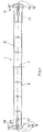
- the separation panel 1 consists of an extruded panel provided with two essentially flat faces 3, 5, possibly provided with a decoration such as a groove, connected together by spacers 7 arranged at regular intervals.
- the two lateral ends 9 and 11 of the panel 1 are equipped with a notch 13 and 15 along the panel 1.
- the bottom of each of these notches is swollen 17.
- each of the ends 9, 11 has, on at least one of the faces 3, 5 of the panel, a projecting edge 19 comprising a lip 21 which extends essentially parallel to the plane of the panel along the length said panel.
- This variant allows the mounting of accessories such as presentation shelves, light fixtures, etc., possibly using fixing means.
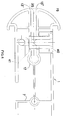
- the flexible connecting member 30 shown in FIG. 2 comprises an essentially flexible part 31 coextruded with, on each side, an essentially rigid part 33, 35.
- the rigid part 33 has a free end with a swollen edge 37 intended to be housed in the swollen bottom notch (13, 17; 15, 17) of the partition panel. It can be introduced into the corresponding notch by longitudinal sliding.
- This assembly constitutes a solid link easily and quickly mountable.
- the other essentially rigid part 35 has essentially flat surfaces and can therefore be introduced into the corresponding notch 13 or 15 of the panel by sliding in a direction essentially perpendicular to the longitudinal direction of the panel.
- the part 33, 37 of the hinge can be previously mounted on the panel. It then suffices to introduce the part 35 into the corresponding notch of another panel.
- FIG 3 there is shown a connecting member according to the invention, which has several branches and which allows, therefore, an arrangement of partition panels in several directions.
- FIG 4 there is shown, by way of example, a means of tightening the notch lips. It is an arrangement of the lockable pin type by which the connecting means (30, 35) is crossed by a pin 40 which can be clamped by means of an eccentric 41 disposed on the opposite face of the panel.
- the partition panel can comprise tubular conduits intended for the possible mounting of a finishing profile comprising an integrated wiring.
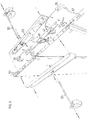
- Figure 5 describes the assembly of several partition panels, as well as the placement of accessories.
- the electrical wiring intended for the lighting or for the supply of such accessories is preferably housed in finishing profiles 45.
- These profiles 45 are arranged on the upper part of the partition panels in which they fit together using of fastening elements 46.
- Said fastening elements 46 have the exact shape of the profile of the lateral end 9 or 11 of the panel concerned.
- connection pins 51 connected by a cable 57 to a panel, and which fit into corresponding sockets of the adjacent panel.
- additional sockets 49 are provided for supplying elements 59 which will directly support auxiliary devices 55 such as lamps ...
Landscapes
- Engineering & Computer Science (AREA)
- Architecture (AREA)
- Physics & Mathematics (AREA)
- Electromagnetism (AREA)
- Civil Engineering (AREA)
- Structural Engineering (AREA)
- Electrical Discharge Machining, Electrochemical Machining, And Combined Machining (AREA)
- Connection Of Plates (AREA)
- Panels For Use In Building Construction (AREA)
- Installation Of Indoor Wiring (AREA)
- Arrangement Of Elements, Cooling, Sealing, Or The Like Of Lighting Devices (AREA)
Applications Claiming Priority (2)
| Application Number | Priority Date | Filing Date | Title |
|---|---|---|---|
| LU87806 | 1990-09-14 | ||
| LU87806A LU87806A1 (fr) | 1990-09-14 | 1990-09-14 | Assemblage de cloisons de separation |
Publications (3)
| Publication Number | Publication Date |
|---|---|
| EP0475928A2 true EP0475928A2 (de) | 1992-03-18 |
| EP0475928A3 EP0475928A3 (en) | 1992-08-19 |
| EP0475928B1 EP0475928B1 (de) | 1996-01-10 |
Family
ID=19731254
Family Applications (1)
| Application Number | Title | Priority Date | Filing Date |
|---|---|---|---|
| EP91870143A Expired - Lifetime EP0475928B1 (de) | 1990-09-14 | 1991-09-13 | Trennwandzusammenbau |
Country Status (4)
| Country | Link |
|---|---|
| EP (1) | EP0475928B1 (de) |
| AT (1) | ATE132933T1 (de) |
| DE (1) | DE69116278T2 (de) |
| LU (1) | LU87806A1 (de) |
Families Citing this family (1)
| Publication number | Priority date | Publication date | Assignee | Title |
|---|---|---|---|---|
| DE202014002065U1 (de) * | 2014-03-05 | 2015-06-10 | Procédés Chénel Beilken Digital Printing Werbeges. mbH | Stellwandsystem mit Schnellverbinder |
Family Cites Families (7)
| Publication number | Priority date | Publication date | Assignee | Title |
|---|---|---|---|---|
| US1723306A (en) * | 1927-08-02 | 1929-08-06 | Harry E Sipe | Resilient attaching strip |
| DE2419878A1 (de) * | 1974-04-24 | 1975-11-13 | Ernst Moeckl | Verbindungselement fuer stellwaende |
| US4047342A (en) * | 1975-05-05 | 1977-09-13 | Paul Boulva | Panel assembly |
| US4365454A (en) * | 1979-02-21 | 1982-12-28 | Cubit Corporation | Construction system |
| EP0018658A3 (de) * | 1979-05-05 | 1981-01-07 | Alfred Wangler | Linien-,Flächen-oder Raumgebilde und Gelenkverbindung hierfür |
| DE3244743A1 (de) * | 1982-12-03 | 1984-06-07 | Karosserie- und Fahrzeugbau Werner Brandt, 4923 Extertal | Rollwand fuer kuehl- und isolierbehaelter |
| US4625633A (en) * | 1985-08-20 | 1986-12-02 | Center Core, Inc. | Ventilated core unit for service connections |
-
1990
- 1990-09-14 LU LU87806A patent/LU87806A1/fr unknown
-
1991
- 1991-09-13 EP EP91870143A patent/EP0475928B1/de not_active Expired - Lifetime
- 1991-09-13 AT AT91870143T patent/ATE132933T1/de not_active IP Right Cessation
- 1991-09-13 DE DE69116278T patent/DE69116278T2/de not_active Expired - Fee Related
Also Published As
| Publication number | Publication date |
|---|---|
| EP0475928B1 (de) | 1996-01-10 |
| LU87806A1 (fr) | 1992-05-25 |
| DE69116278T2 (de) | 1996-08-08 |
| ATE132933T1 (de) | 1996-01-15 |
| DE69116278D1 (de) | 1996-02-22 |
| EP0475928A3 (en) | 1992-08-19 |
Similar Documents
| Publication | Publication Date | Title |
|---|---|---|
| US5330821A (en) | Decorative device for concealing the top of curtains and certain fixtures | |
| FR2635248A1 (fr) | Boitier destine a recevoir des elements electriques et electroniques | |
| CA2545299A1 (fr) | Accessoire pour la rehausse et l'eclissage de chemins de cables en fils | |
| FR2475346A1 (fr) | Logement modulaire pour boite de distribution electrique | |
| FR2639481A1 (fr) | Dispositif formant connecteur electrique | |
| MX2007003379A (es) | Perfil para pared de iluminacion y sistema de perfil de pared de iluminacion. | |
| FR2543498A1 (fr) | Installation de conducteur de courant electrique a frottement | |
| EP0475928B1 (de) | Trennwandzusammenbau | |
| EP0726624B1 (de) | Verbindungsanordnung | |
| FR2672741A1 (fr) | Armoire electrique avec un bati et un socle. | |
| EP0473589A1 (de) | Befestigungsmittel. | |
| CA2749382C (fr) | Platine de fixation reglable pour tendre sans deformation par des cables une nappe souple | |
| EP1052454A1 (de) | Industrie-Innenleuchte | |
| US20050102879A1 (en) | Decorative corner piece for connecting mitered frame sections together | |
| US20030012017A1 (en) | Built-in modular lighting elements and strips of such elements | |
| FR2654188A1 (fr) | Ensemble d'eclairage comprenant un element support destine a etre fixe sur une gaine technique. | |
| JP3912692B2 (ja) | オープンショーケースにおける風防ガラスの取付構造 | |
| FR2656387A1 (fr) | Dispositif pour assembler deux ou plusieurs elements de construction autour d'un axe central. | |
| FR2717554A1 (fr) | Ensemble pour déterminer l'écartement d'organes de fixation de câblages électriques. | |
| JP3909071B2 (ja) | 棚板支持具 | |
| FR2698731A1 (fr) | Connecteur électrique. | |
| BE1004375A3 (fr) | Encadrement decoratif. | |
| CA1296045C (fr) | Systeme d'assemblage montable, demontable et autobloquant d'elements de structure | |
| FR2649253A1 (fr) | Boite d'encastrement en deux parties, notamment pour appareillage electrique | |
| FR2707821A3 (fr) | Panneau de commande d'interphone vidéo modulaire sectionnel, destiné à un câblage simplifié. |
Legal Events
| Date | Code | Title | Description |
|---|---|---|---|
| PUAI | Public reference made under article 153(3) epc to a published international application that has entered the european phase |
Free format text: ORIGINAL CODE: 0009012 |
|
| AK | Designated contracting states |
Kind code of ref document: A2 Designated state(s): AT BE CH DE DK ES FR GB GR IT LI NL SE |
|
| PUAL | Search report despatched |
Free format text: ORIGINAL CODE: 0009013 |
|
| AK | Designated contracting states |
Kind code of ref document: A3 Designated state(s): AT BE CH DE DK ES FR GB GR IT LI NL SE |
|
| 17P | Request for examination filed |
Effective date: 19921229 |
|
| 17Q | First examination report despatched |
Effective date: 19940201 |
|
| GRAA | (expected) grant |
Free format text: ORIGINAL CODE: 0009210 |
|
| AK | Designated contracting states |
Kind code of ref document: B1 Designated state(s): AT BE CH DE DK ES FR GB GR IT LI NL SE |
|
| PG25 | Lapsed in a contracting state [announced via postgrant information from national office to epo] |
Ref country code: DK Effective date: 19960110 Ref country code: IT Free format text: LAPSE BECAUSE OF FAILURE TO SUBMIT A TRANSLATION OF THE DESCRIPTION OR TO PAY THE FEE WITHIN THE PRE;WARNING: LAPSES OF ITALIAN PATENTS WITH EFFECTIVE DATE BEFORE 2007 MAY HAVE OCCURRED AT ANY TIME BEFORE 2007. THE CORRECT EFFECTIVE DATE MAY BE DIFFERENT FROM THE ONE RECORDED.SCRIBED TIME-LIMIT Effective date: 19960110 Ref country code: NL Free format text: LAPSE BECAUSE OF FAILURE TO SUBMIT A TRANSLATION OF THE DESCRIPTION OR TO PAY THE FEE WITHIN THE PRESCRIBED TIME-LIMIT Effective date: 19960110 Ref country code: AT Effective date: 19960110 Ref country code: GB Effective date: 19960110 Ref country code: GR Free format text: LAPSE BECAUSE OF FAILURE TO SUBMIT A TRANSLATION OF THE DESCRIPTION OR TO PAY THE FEE WITHIN THE PRESCRIBED TIME-LIMIT Effective date: 19960110 Ref country code: ES Free format text: THE PATENT HAS BEEN ANNULLED BY A DECISION OF A NATIONAL AUTHORITY Effective date: 19960110 |
|
| REF | Corresponds to: |
Ref document number: 132933 Country of ref document: AT Date of ref document: 19960115 Kind code of ref document: T |
|
| REF | Corresponds to: |
Ref document number: 69116278 Country of ref document: DE Date of ref document: 19960222 |
|
| PG25 | Lapsed in a contracting state [announced via postgrant information from national office to epo] |
Ref country code: SE Effective date: 19960410 |
|
| NLV1 | Nl: lapsed or annulled due to failure to fulfill the requirements of art. 29p and 29m of the patents act | ||
| GBV | Gb: ep patent (uk) treated as always having been void in accordance with gb section 77(7)/1977 [no translation filed] |
Effective date: 19960110 |
|
| PG25 | Lapsed in a contracting state [announced via postgrant information from national office to epo] |
Ref country code: LI Effective date: 19960930 Ref country code: CH Effective date: 19960930 |
|
| PLBE | No opposition filed within time limit |
Free format text: ORIGINAL CODE: 0009261 |
|
| STAA | Information on the status of an ep patent application or granted ep patent |
Free format text: STATUS: NO OPPOSITION FILED WITHIN TIME LIMIT |
|
| 26N | No opposition filed | ||
| REG | Reference to a national code |
Ref country code: CH Ref legal event code: PL |
|
| PGFP | Annual fee paid to national office [announced via postgrant information from national office to epo] |
Ref country code: BE Payment date: 19980727 Year of fee payment: 8 |
|
| PGFP | Annual fee paid to national office [announced via postgrant information from national office to epo] |
Ref country code: DE Payment date: 19980814 Year of fee payment: 8 |
|
| PGFP | Annual fee paid to national office [announced via postgrant information from national office to epo] |
Ref country code: FR Payment date: 19980917 Year of fee payment: 8 |
|
| PG25 | Lapsed in a contracting state [announced via postgrant information from national office to epo] |
Ref country code: BE Free format text: LAPSE BECAUSE OF NON-PAYMENT OF DUE FEES Effective date: 19990930 |
|
| BERE | Be: lapsed |
Owner name: S.A. QUICK LOCK PANEL Effective date: 19990930 |
|
| PG25 | Lapsed in a contracting state [announced via postgrant information from national office to epo] |
Ref country code: FR Free format text: LAPSE BECAUSE OF NON-PAYMENT OF DUE FEES Effective date: 20000531 |
|
| PG25 | Lapsed in a contracting state [announced via postgrant information from national office to epo] |
Ref country code: DE Free format text: LAPSE BECAUSE OF NON-PAYMENT OF DUE FEES Effective date: 20000701 |
|
| REG | Reference to a national code |
Ref country code: FR Ref legal event code: ST |